Transcription
Lecture 8Power Dividers and CouplersA. Nassiri -ANLMassachusetts Institute of TechnologyRF Cavities and Components for AcceleratorsUSPAS 2010
Power dividers and directional couplers Basic properties of dividers and couplers three-port network (T-junction), four-port network (directional coupler),directivity measurement The T-junction power divider Lossless divider, lossy divider The Wilkinson power divider Even-odd mode analysis, unequal power division divider, N-way Wilkinson divider The quadrature (90 ) hybrid branch-line coupler Coupled line directional couplers Even- and odd-mode Z0, single-section and multisection coupled line couplers The Lange coupler The 180 hybrid - rat-race hybrid, tapered coupled line hybrid Other couplers reflectometerMassachusetts Institute of TechnologyRF Cavities and Components for AcceleratorsUSPAS 20102
Basic properties of dividers and couplers N-port networkMassachusetts Institute of TechnologyRF Cavities and Components for AcceleratorsUSPAS 20103
Three-port network (T-junction)Discussion1. Three-port network cannot be lossless, reciprocal and matched at all ports.2. Lossless and matched three-port network is nonreciprocalcirculatorMassachusetts Institute of TechnologyRF Cavities and Components for AcceleratorsUSPAS 20104
3. Matched and reciprocal three-port network is lossyresistive divider4. Lossless and perfect isolation three-port network cannot be matched atall ports.Massachusetts Institute of TechnologyRF Cavities and Components for AcceleratorsUSPAS 20105
Four-port network (directional coupler)Input port 1Through port 2Isolated port 4Coupled port 3Coupling:Directivity:Isolation:Massachusetts Institute of TechnologyRF Cavities and Components for AcceleratorsUSPAS 20106
Discussion1. Matched, reciprocal and lossless four-networksymmetrical(90 ) directional coupler or antisymmetrical (180 ) directionalcoupler.2. C 3dB90 hybrid (quadrature hybrid, symmetrical coupler),180 hybrid (magic-T hybrid, rate-race hybrid)Massachusetts Institute of TechnologyRF Cavities and Components for AcceleratorsUSPAS 20107
The T-junction power divider Lossless divider“not practical”Lossless divider has mismatched portsMassachusetts Institute of TechnologyRF Cavities and Components for AcceleratorsUSPAS 20108
Resistive (lossy) dividermatched portsMassachusetts Institute of TechnologyRF Cavities and Components for AcceleratorsUSPAS 20109
Wilkinson power divider Basic conceptInput port 1 matched, port 2 and port 3 have equal potential 2Z 0 , λ 4Input port 2, port 1 and port 3 have perfect isolationlossy, matched and good isolation (equal phase) three-port dividerMassachusetts Institute of TechnologyRF Cavities and Components for AcceleratorsUSPAS 201010
Wilkinson power divider The Wilkinson power divider has these advantages:1. It is lossless when output ports are matched.2. Output ports are isolated.3. It can be designed to produce arbitrary power division.Port 2λ/4Port 12Z 0Z0Z0Film resistorR 2Z0Z02Z 0λ/4 2Z 0 2Z b aPort 1Z0Massachusetts Institute of Technology 0Port 2Port 3Z0R 2Z0Z0RF Cavities and Components for AcceleratorsPort 3USPAS 201011
Wilkinson power divider If we inject a TEM mode signal at port 1, equal in-phase signals reachpoints a and b. Thus, no current flows through the resistor, and equalsignals emerge from port 2 and port 3. The device is thus a 3dB powerdivider. Port 1 will be matched if the λ/4 sections have a characteristicimpedance 2Z 0 . If we now inject a TEM mode signal at port 2, with matched loads placedon port 1 and on port 3, the resistor is effectively grounded at point b. Equalsignals flow toward port 1, and down into the resistor, with port 2 seeing amatch. Half the incident power emerges from port 1 and half is dissipated inthe resistor film. Similar performance occurs when port 1 and port 2 are terminated inmatched loads, and a TEM mode signal is injected at port 3. If we choose the terminal planes at 1.0 wavelengths from the three Teejunctions, the scattering matrix is 01 [S ] j2 jMassachusetts Institute of TechnologyRF Cavities and Components for Accelerators j00 j 0 0 USPAS 201012
Wilkinson power divider for unequal power splitsP2Z 02P1R2 KZ0Z0Z 03P3R3 Z0/KMassachusetts Institute of TechnologyRF Cavities and Components for AcceleratorsUSPAS 201013
Wilkinson power dividerDesign a Wilkinson power divider with a power division ration of 3 dB and a sourceimpedance of 50 ΩSolution:P3 0.5(3dB )P2P3 12K K 0.707P2 2Z 03 Z 01 K 2K31 0.5 50 103.0 Ω(.5)(.707 )Z 02 K Z 03 (.5)(103Ω ) 51.5Ω21 1 R Z 0 K 50 0.707 106.1ΩK 0.707 Massachusetts Institute of TechnologyRF Cavities and Components for AcceleratorsUSPAS 201014
Wilkinson power dividerThe output impedances areR 2 Z 0K 50(0.707 ) 35.35ΩR 3 Z 0 K 50 / 0.707 70.72Ω 50ΩZ 03 103ΩR 106.1ΩZ 02 51.5Ω Massachusetts Institute of TechnologyZ 0 50ΩZ 0 50ΩRF Cavities and Components for AcceleratorsUSPAS 201015
Bethe-Hole Directional CouplerThis the simplest form of a waveguide directional coupler. A small hole in thecommon broad wall between two rectangular guides provides 2 wave componentsthat add in phase at the coupler port, and are cancelled at the isolation port.3yCoupling etts Institute of TechnologyRF Cavities and Components for AcceleratorsUSPAS 201016
Bethe-Hole Directional CouplerLet the incident wave at Port 1 be the dominant TE10 mode:Top GuidePort 3(coupled)E y A sinHx πxae jβ zπxAsin e jβzZ 10a A10 A10 A10Port 1(input)Couplinghole A10Port 2(through)Bottom GuideZA amplitude of electric field (V m-1)Z0 η01 (λ 0 2a )2πx jβzjπAcos eHz βaZ 10aβ κ 0 1 (λ 0 2a )2 wave impedance,dominate mode,Ω phase constant rad/mκ 0 2π λ 0Massachusetts Institute of TechnologyRF Cavities and Components for AcceleratorsUSPAS 201017
Bethe-Hole Directional CouplerIn the bottom guide the amplitude of the forward scattered wave is given byjωA 2 πs µ 0 α m A10 ε 0αe sin2P10 aZ 102 2 πs ππs2 sin cos22 aaβa while the amplitude of the reversed scattered wave is given byµ 0α mωA 2 πs A10 ε 0αe sin2P10 aZ 10whereP10 abZ 102 2 πs ππs2 sin cos2 2 aaβa For round coupling hole or radius r0, we have2 2αe r034 2α m r03electric polarizabilitymagnetic polarizabilityMassachusetts Institute of TechnologyRF Cavities and Components for AcceleratorsUSPAS 201018
Bethe-Hole Directional CouplerLet s offset distance to holeasWe can then show thatsinπsa (λ02 λ20 a 2)The coupling factor for a single-hole Bethe Coupler isAC 20log (dB )A10and its directivity is A10D 20log (dB )A10Massachusetts Institute of TechnologyRF Cavities and Components for AcceleratorsUSPAS 201019
Bethe-Hole Directional CouplerDesign procedure:1. Use2. Usesinπsa C 20 log(λ02 λ20 a 2A A10(dB ))to find position of hole.to determine the hole radius r0 togive the required coupling factor.Massachusetts Institute of TechnologyRF Cavities and Components for AcceleratorsUSPAS 201020
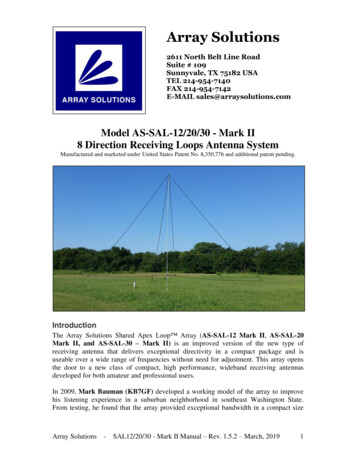
Bethe-Hole Directional CouplerTypical x-Band -20 dB coupler0CC ( dB) - 20D (dB)D- 40- 6067891011Frequency (GHz)Note: Coupling very broad band, directivity is verynarrow band (for single-hole coupler)We can achieve improved directivity bandwidth byusing an array of equispaced holes.Massachusetts Institute of TechnologyRF Cavities and Components for AcceleratorsUSPAS 201021
Bethe-Hole Directional CouplerUPPER GUIDE Port 4(ISO)B0F0 B1F1 B2F2 BNPort 1B0F0 B1F1F2B2FNBNFN Port 4CouplPort 2TRU n 0n 1dn 2dn NdLet a wave of value 1 0 be injected at Port 1. If the holes are small, there isonly a small fraction of the power coupled through to the upper guide so thatwe can assume that the wave amplitude incident on all holes is essentiallyunity. The hole n causes a scattered wave Fn to propagate in the forwarddirection, and another scattered wave Bn to propagate in the backwarddirection. Thus the output signals are:Massachusetts Institute of TechnologyRF Cavities and Components for AcceleratorsUSPAS 201022
Bethe-Hole Directional CouplerPort 1 (input)and Port 4 (isolated)Port 2 (through)B (1) B (4 ) (2 ) FTotalN j 2 nβdBe nn 0 jNβ de e jNβdN Fnmain incident wave 0 n Nforward scattered waves()jNd3 2βPort 3 (coupled)F eFnn 0All of these waves are phase referenced to the n 0 hole.NC 20 log F (3) 20 logF n dBn 0N j 2β ndBen(4)BD 20 log (2 ) 20 log n 0 NdB ( ) F Fn( )n 0Massachusetts Institute of TechnologyRF Cavities and Components for AcceleratorsUSPAS 201023
Bethe-Hole Directional CouplerWe can rewrite this asNNn 0n 0D 20 log B ne j 2βnd 20 log F n C 20logN j 2βndBe nn 0The coupling coefficients are proportional to the polarizability αe and αm ofthe coupling holes. Let rn radius of the nth hole. Then the forward scatteringcoefficient from the nth hole is (n )F n A10And the backward scattering from the hole is (n )B n A10Massachusetts Institute of TechnologyRF Cavities and Components for AcceleratorsUSPAS 201024
Bethe-Hole Directional CouplerNow let us assume the coupling holes are located at the midpoint acrosscommon broad wall, i.e. s a/2. Then for circular holed, we haveFn Butωε 0 A10k02ωε 0 A 2µ 0 3 j 1 rn23P10 ε 0 Z 10 andη0 F n K f rn32Z 10 η02 1 (λ 2a )2 0 η02f1 c f 22 f j 2 k0 A where K f 1 2 1 c f 3η0P10 Let A 1 v/m. Then j 2 k0Kf 3η0P10Massachusetts Institute of Technology f 2 2 c 1 f RF Cavities and Components for AcceleratorsUSPAS 201025
Bethe-Hole Directional CouplerLikewise the backward scattering coefficient is2 k0Kb 3η0P10 f 2 2 c 3 f andβn K b rn3Note that Kf and Kb are frequency-dependent constants that are the same forall aperture. Thus,NC 20 log K f 20 log3r n(dB )n 0ND C 20 log K b 20 log rn3e j 2βnd(dB )n 0Massachusetts Institute of TechnologyRF Cavities and Components for AcceleratorsUSPAS 201026
Bethe-Hole Directional CouplerConsider the following design problem:Given a desired coupling level C, how do we design the coupler so that the directivity D isabove a value Dmin over a specified frequency band? N FnNote that if the coupling C is specified, thenis known.n 0We now assume that either (1) the holes scatter symmetrically (e.g. they areon the common narrow wall between two identical rectangular guides) or (2)holes scatter asymmetrically (e.g. they are on the centerline of the commonbroad wall, i.e. s a/2 ). Thus:orBn F nB n F nN FnIn either case, we haveD 20logn 0N F ne j 2βndn 0Massachusetts Institute of TechnologyRF Cavities and Components for AcceleratorsUSPAS 201027
Bethe-Hole DirectionalCouplerNThus, keeping the directivity D Dmin is equivalent to keeping j 2βndFe nn 0below a related minimum value. Letϕ 2βd and w e jφ e j 2βdWe also introduce the functiong (βd ) N j 2β nd g (φ) Fe nn 0 g (w ) NnFw nn 0Thus we haveD 20logg (1) NNjnφFe nn 0NFn n FN w F N (w w n )Fn 0 Nn 1Ng (1)g (w ) C / 20F 10 nCouplingfactor (dB)n 0Massachusetts Institute of TechnologyRF Cavities and Components for AcceleratorsUSPAS 201028
Bethe-Hole Directional CouplerFrom the previous two equations we can deduce thatgmax g (1) 10 D min / 20The multi-hole coupler design problem thus reduces to finding a set of roots wnthat will produce a satisfactory g(w), and thus a satisfactory D(f) in the desiredfrequency band under the constraint thatg (w ) gmax .Example: Design a 7-hole directional coupler in C-band waveguide with a binomialdirectivity response to provide 15 dB coupling and with Dmin 30 dB. Assume an operatingcenter frequency of 6.45 GHz and a hole spacing d λg/4 (or λg λg/4). Also assume broadwall coupling with s a/2.Solution:From g (w ) F NN (w w n ), we haven 16g (w ) F 6 (w w n ) where w n e j 2βd 1() g (w ) F 6 (w 1)6 F 6 w 6 6w 5 15w 4 20w 3 15w 2 6w 1Massachusetts Institute of TechnologyRF Cavities and Components for AcceleratorsUSPAS 201029
Bethe-Hole Directional CouplerThus,g (1) F 6 (1 1)6 64 F 6 10 15 20 0.1778 F 6 0.00278 F 0By the binomial expansion we have(wwhere, 1) 6C n(6 ) 6(6 )w nC nn 06!N! (N n )! n! (6 n )! n!is the set of binomial coefficientsThusF 5 F1 6 F 6 0.01667F 4 F 2 15 F 6 0.04168F 3 20 F 6 0.05557Massachusetts Institute of TechnologyRF Cavities and Components for AcceleratorsUSPAS 201030
Bethe-Hole Directional CouplerWe now can compute the radii of the coupling holed fromF n K f rn3where2 f j 2 k0 A Kf 1 2 1 c f 3η0P10 and2 j 2 k0 f c Kf 2 1 3η0P10 f We have – with fc 4. 30 GHz for C-Band guide, f 6.45 GHz, k0 2π/λ0 135.1 m-1,η0 376.7 Ω, P10 ab/Z10,Z 10 η0Kf f 1 c f 2 505.4Ω , P10 1.08 10 6 m 2 Ω2 135.13 376.7 1.08 10 6Massachusetts Institute of Technology 4.30 2 2 1 24598 6.45 RF Cavities and Components for AcceleratorsUSPAS 201031
Bethe-Hole Directional CouplerThe hole radii are:13 0.00278 r0 Kf 0.00483m r6 0.483cm13 0.01667 0.00878m r5 0.878cmr1 Kf 13 0.04168 0.011921m r4 1.192cmr2 Kf 13 0.05557 r3 Kf 0.0131m 1.31cmMassachusetts Institute of TechnologyRF Cavities and Components for AcceleratorsUSPAS 201032
Bethe-Hole Directional Coupler4.68 cm2r0 0.966cm 2r1 1.756cma 3.485cm2 r3 2.62cm2 r2 2.384cmTop view of C-Band guide common broad wall with coupling holesThe guide wavelength isλ0λg 2 0.624 m 4.3 1 6.45 λg 1.56cm . However, the center holeThe nominal hole spacing is d 4has a diameter of 2.62 cm, so it would overlap with adjacent holes. We can3λgincrease the hole spacing to d 4.68cm4performance.with no effect on electricalThe total length of the common broad wall section with coupling holes is 30 cm, which is fairly large WG section.Massachusetts Institute of TechnologyRF Cavities and Components for AcceleratorsUSPAS 201033
Bethe-Hole Directional CouplerWe now plot the coupling and directivity vs. frequency6φ φ j φ j φ jj6φ 2 26jφ g (w ) F 6 (w 1) F 6 e 1 F 6 ee e 2 F 6 2e 2 cos 2 ()6φφ6 g (w ) 2 F 6 cos 0.1778 cos2266We then haveg (w )2πdD (dB ) 20 log 120 log cosg (1)λgwhere d 4.68 cmλg λ01 (λ 0 2a )2Massachusetts Institute of Technology (3 108 f )1 (f c f)2RF Cavities and Components for AcceleratorsUSPAS 201034
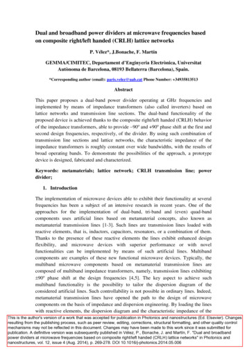
Bethe-Hole Directional Coupler0-10D (dB)-20900 MHz-30-40Dmin-505.756.06.256.56.75Frequency (GHz)7.07.257.5Note that the directivity is better than Dmin -30 dB over a bandwidth of 900 MHzcentered about 6.45 GHz.Massachusetts Institute of TechnologyRF Cavities and Components for AcceleratorsUSPAS 201035
Even-odd mode analysisMassachusetts Institute of TechnologyRF Cavities and Components for AcceleratorsUSPAS 201036
Even-modeSymmetry of port 2 and 3Massachusetts Institute of TechnologyRF Cavities and Components for AcceleratorsUSPAS 201037
Odd-modesymmetry of port 2 and 3,open, short at bisection S 32 S 23port 1 matched S11 0Massachusetts Institute of TechnologyRF Cavities and Components for AcceleratorsUSPAS 201038
Discussion3dB Wilkinson power divider has equal amplitude and phase outputs at port2 and port 3.3dB Wilkinson power combinerMassachusetts Institute of TechnologyRF Cavities and Components for AcceleratorsUSPAS 201039
Unequal power division Wilkinson power dividerMassachusetts Institute of TechnologyRF Cavities and Components for AcceleratorsUSPAS 201040
Massachusetts Institute of TechnologyRF Cavities and Components for AcceleratorsUSPAS 201041
N-way Wilkinson power dividerMassachusetts Institute of TechnologyRF Cavities and Components for AcceleratorsUSPAS 201042
The quadrature (90 ) hybrid Branch-line couplerPort 2 and port 3 have equal amplitude, but 90 phase differentInput1Z0OutputZ02Z02λ/4λ/44Z0IsolatedA1 11 1 B1 0dB 0 1 2141 1 B4Massachusetts Institute of Technology2 2B2 0 1 j[S ] 2 13 3dB 90 011B33 3dB 90 2 Z0Output111Z01RF Cavities and Components for AcceleratorsUSPAS 2010j001100j0 1 j 0 43
Quadrature HybridsWe can analyze this circuit by using superposition of even-modes and 0ddmodes. We add the even-mode excitation to the odd-mode excitation to producethe original excitation of A1 1 volt at port 1 (and no excitation at the other ports.) 211/24 1 1 1 1 1 2 1211 32 1 2 11 1 1 1 1Even Mode Excitation1 1 1 2 1-1/24 11 1 1 1 2 1 1 32 1Line of symmetry v 0, I max 1 1 1 12 Open circuit(2 separate 2-ports)Line of symmetry I 0, v max1/22Γ0 1 2 12 1/21 1 1 11 T0 1 21short circuit stubs(2 separate 2-ports)Odd Mode ExcitationMassachusetts Institute of TechnologyRF Cavities and Components for AcceleratorsUSPAS 201044
Quadrature HybridsWe now have a set of two decoupled 2-port networks. Let Γe and Te be thereflection and transmission coefficients of the even-mode excitation. Similarly Γoand Te for the odd-mode excitation.Superposition:11 B1 Γe Γo 22 11Through B 2 Τe Τo 22 Reflected 11wavesCoupled B3 Τe Τo 22 11 Isolated B 4 Γe Γo 22 InputMassachusetts Institute of TechnologyRF Cavities and Components for AcceleratorsUSPAS 201045
Quadrature HybridsConsider the even-mode 2-port circuit:Port 1λ 4Inputλ8 1 2 λ8openPort 2Coupledopenλ 8 open circuit stubs by their admittance:π1 j tanz4y lim L jjπz L 1 tanzL4We can represent the twoThe λ 4 transmission line, with characteristic impedance 1ABCD matrix 0 j 2Massachusetts Institute of Technologyj2has ab2 0 RF Cavities and Components for AcceleratorsUSPAS 201046
Quadrature HybridsThus, the ABCD matrix for the cascade isj 1 0 1 1 j A B 1 0 0 2 C D j 1 j 1 2 j 1 e j 2 0 λ 8 stubλ 4 lineλ 8 stubUsing the conversion table (next slide) to convert [S] parameters (with Z0 1 asthe reference characteristic impedance).Bjj11 CZ 0 D Z02222B CZ 0 DA Z0( 1 j j 1) 2Γe S11 0B() 1 j j 1 2 CZ 0 DA Z0221(1 j )Τe S 21 B2A CZ 0 D ( 1 j j 1) 2Z01(1 j )Similarly for odd mode we have: S 11 Γ0 0 and S 12 Τ0 2denominatorMassachusetts Institute of Technology A RF Cavities and Components for AcceleratorsUSPAS 201047
Conversion between two-port network parametersSZYABCDD. PozarMassachusetts Institute of TechnologyRF Cavities and Components for AcceleratorsUSPAS 201048
Quadrature HybridsTherefore we haveScattered wavevoltages B1 0 B 2 B3 B 0 4(port 1 is matched)j212Through (half power, -900 phase shift port 1 to 2)(half power, -1800 phase shift port 1 to 3)(no power to port 4)The bandwidth of a single branch-line hybrid is about 10% - 20%, due to therequirement that the top and bottom lines are λ/4 in length. We can obtainincreased directivity bandwidth (with fairly constant coupling) by using three ormore sections.Massachusetts Institute of TechnologyRF Cavities and Components for AcceleratorsUSPAS 201049
Quadrature HybridsNext we consider a more general single section branch-line coupler:InputZ0Z01Z0Through Output12Z02λ 4Z0243IsolatedZ0Z01Z0Output (coupled)λ 4We can show that if the conditionZ 02Z 01 Z 0 Z01 (Z 01 Z 0 )2is satisfied, then port 1 is matched; port 4 is decoupled from port 1.Massachusetts Institute of TechnologyRF Cavities and Components for AcceleratorsUSPAS 201050
Quadrature HybridsSingle section branch-line coupler B1 0 Z B 2 j 01scattered wave Z0voltages B Z 01 Z 0 3Z 02 Z 0 isolated B 4 0matched 0 90 180 (matched)Thus, the directivity is theoretically infinite at the design frequency. We canalso show that the coupling is given by 1(dB )C 10log 2 1 (Z 01 Z 0 ) For stripline microstrip, we control Z01/Z0 by varying the strip width, in coaxby adjusting the ratio b/a, and in the rectangular guide by changing the bdimension.Massachusetts Institute of TechnologyRF Cavities and Components for AcceleratorsUSPAS 201051
Quadrature HybridsExample:Design a one-section branch-line directional coupler to provide a coupling of 6 dB.Assume the device is to be implemented in microstrip, with an 0.158 cm substratethickness, a dielectric constant of 2.2, and that the operating frequency is 1.0 GHz.Solution: 1C 10 log 62 1 (Z 01 Z 0 ) (dB ) Z 01 Z 0 0.8653 Z 01 43.27ΩZ 02Z 01 Z 0 1.7263 Z 02 86.31Ω2Z01 (Z Z )01λ 0λ030 20.226 cmεr2.2l λ 5.0565 cm4εr 1 w 2 0.61 3.081 B 1 ln(2B 1) ln 1B 1 .39 ε r d π 2ε r w 0.487 cmMassachusetts Institute of TechnologyRF Cavities and Components for AcceleratorsUSPAS 201052
Quadrature HybridsFor Z 01 43.27Ω, w 1 0.601cmw28e AFor Z 02 86.31Ω , 2A 1.1675d e 1w 2 0.185cm0.4868 cmInput(0 dB)Through(-1.26dB)0.6008 cmZ01Z05.0565 cmZ0Z02Z020.1845 cmZ01IsolatedZ0Z0Coupled(-6dB)5.0565 cmWith 0 dB power input at the upper left arm, the power delivered to a matched load(in )at the through arm isP2 (dB ) 10 logP1110log B 2B 2*P2(out )22 Z0 50 10 log 10 log 1.26dBZ4327. 01 Massachusetts Institute of TechnologyRF Cavities and Components for AcceleratorsUSPAS 201053
Coupled Line Directional CouplersThese are either stripline or microstrip 3-wire lines with close proximity of parallellines providing the coupling.Co-planar striplineSide-stacked coupled striplineBroadside-stacked coupler striplineCo-planar microstripopen ckt0Veven mode0Vshort ckt0Vodd mode0VMassachusetts Institute of TechnologyRF Cavities and Components for AcceleratorsUSPAS 201054
Theory of Coupled LinesC12 C22C11Three-wire coupled lineC12C11 ,C22 Equivalent networkcapacitance between two strip conductors in absence of the ground conductor.capacitance between one conductor and groundIn the even mode excitation, the currents in the strip conductors are equal inamplitude and in the same direction.In the odd mode excitation, the currents in the strip conductors are equal inamplitude but are in opposite directions.Massachusetts Institute of TechnologyRF Cavities and Components for AcceleratorsUSPAS 201055
Theory of Coupled Lines In the even mode, Efields have even symmetry about centerline, and nocurrent flows between strip conductors. Thus C12 is effectively open-circuited.The resulting capacitance of either line to ground isCe C11 C22The characteristic impedance of the even modes isZ 0e L1 C e νC eIn the odd mode, E fields have an odd symmetry about centerline, and avoltage null exists between the strip conductors. 2C12 C112C12The effective capacitance betweeneither strip conductor and ground is C0 C11 2 C12 C22 2 C12C22 Massachusetts Institute of TechnologyZ 0oRF Cavities and Components for AcceleratorsL1 C o νC oUSPAS 201056
Theory of Coupled LinesExample: An edge-coupled stripline with εr 2.8 and a ground plane spacing of 0.5cm is required to have even- and odd-mode characteristic impedance of Z0e 100 Ωand Z0o 50 Ω. Find the necessary strip widths and spacing.εr 2.8Solution: b 0.50 cm, εr 2.8, Z0e 100 Ω, Z0o 50 Ω ε r Z 0e 167.3 evenε r Z 0o 83.66 b .5cmoddfrom the graph, s/b 0.095, W/b 0.32WWsS 0.95 b 0.095 0.5 0.0425 cmW 0.32b 0.32 0.5 0.16 cm0.16cm0.5cmMassachusetts Institute of TechnologyRF Cavities and Components for Accelerators0.16cmεr 2.80.0425cmUSPAS 201057
Waveguide magic-T 4231Σ424332Input at port 1Input at port 4Port 4:0Port 1:0Ports 2 and 3: equal amplitude andphasePorts 2 and 3: 1800 phase differenceMassachusetts Institute of TechnologyRF Cavities and Components for AcceleratorsUSPAS 201058
Even Mode ABCD AnalysisConsider the equivalent circuit for the even mode:1 2Γeλ4 212λ23λ828ΤeAt port 1, the admittance looking intothe λ/8 o.c. stub isy S 1 y 0 ( j tan βl ) j1 2π λ j tan λ 8 2 2o.c.o.c.The ABCD matrix of a shunt admittance yS1 isA 1 Y2/Y3Y3B 1/Y3Y1Y2C Y1 Y2 Y1Y2/Y3 A B 1 C D j 1 20 1 D 1 Y1/Y3Massachusetts Institute of TechnologyRF Cavities and Components for AcceleratorsUSPAS 201059
Even Mode ABCD AnalysisAt port 2, the admittance looking into the 3λ/8 o.c. stub isy S 2 y 0 ( j tan βl ) j1 2π 3λ j tan λ 8 2 2The ABCD matrix of this shunt admittance is0 1 Zo 2The ABCD matrix is cos βl A B C D jy sin βl 2 o wherejZ o sin βl ys2Zo 2quarter-wave sectioncos βl βl 2π λ π 4 π 2Zo 2,y o 1 2Massachusetts Institute of Technologyys1{ 1 A B C D j 3 2λ 4 0 A B j C D 2 2 RF Cavities and Components for AcceleratorsUSPAS 2010j 2 0 60
Even Mode ABCD AnalysisWe can now compute the ABCD matrix of the even mode cascadeλ 41λ222283λ8o.c.o.c. 1 A B C D j e 20 0 j 1 2j 2 1 1 j 20 1 j 1 2j 2 Massachusetts Institute of Technology j0 2 10 j 2 RF Cavities and Components for Accelerators0 1 j 2 1 USPAS 201061
Odd Mode ABCD AnalysisThe input admittance to a shortcircuited lossless stub isy in y 0 ( j cot βl )Thus the input admittance to thes.c. λ/8 tub is1 2Γoj1 2π λ y S1 j cot λ 8 2 2λ41λ28222yS2s.c.0 1 j1 2π 3λ j cot λ 8 2 2Massachusetts Institute of Technology3λ8s.c.ABCD matrix: A B 1 C D j 1 2Τo(Input admittance to s.c. 3λ/8 stub)RF Cavities and Components for AcceleratorsUSPAS 201062
Odd Mode ABCD Analysisand 1 A B C D j 3 20 1 So the ABCD matrix of the odd-mode cascade is 1 A B C D j o 20 0 j 1 2 1 j 2j 2 Γe jΓo j0 20 1 1 2 , Τe j2 , Τo jMassachusetts Institute of Technologyj 2 1 j22RF Cavities and Components for AcceleratorsUSPAS 201063
Excitation at Port 4We have derived the ABCD matrices for the Even (e) and Odd (o) modes: 1 A B C D e j 2 j 2 1 and 1 A B C D o j 2j 2 1 For excitation at Port 4 instead of Port 1 the ABCD matrices remain thesame. What changes are the definitions of Γ and T for each mode and theirrelations to B1 – B4 achusetts Institute of TechnologyRF Cavities and Components for AcceleratorsUSPAS 201064
Excitation at Port 4Even mode:Γe S 22 1 A B C D e j 2 A B CZ o DZoA B Z CZ o Dj 2 1 Γe j 1 j 2 j 2 1 2 j2 21 j 2 j 2 12Τe j2( 1 2 )2 1 j 2 j 2 1 j 2 22oΤe S122(AD BC ) A B Z o CZ 0 D 1 A B C D o j 2Odd mode:j 2 1 j1 j 2 j 2 12 1 j 2 j 2 1 j 2 22j2( 1 2 )2 1 j 2 j 2 1 j 2 22Γo S 22 Τo S12Excitation at Port 4 is expressed as :EvenV 2 1 2V 4 1 2Massachusetts Institute of TechnologyOddV 2 1 2V 4 1 2RF Cavities and Components for AcceleratorsUSPAS 201065
Excitation at Port 4 of Rat-Race Coupler (cont.)Γe Γo jjΤe 2j2Τo 112211B 2 Γe Γo2211B3 Τe Τo2211B 4 Γe Γo22B1 Τe Τo2Output wavesj2The resulting output vector for unit excitation at Port 4 is :[B i ]4Massachusetts Institute of Technology0 j2 2 j 0 RF Cavities and Components for AcceleratorsUSPAS 201066
The T-junction power divider Lossless divider, lossy divider The Wilkinson power divider Even-odd mode analysis, unequal power division divider, N-way Wilkinson divider The quadrature (90 ) hybrid branch-line coupler Coupled line directional couplers Even- and odd-mode Z 0, single-section and multisection coupled line