Transcription
BGM13S Blue Gecko Bluetooth SiPModule Data SheetThe BGM13S is Silicon Labs’ first SiP module solution for Bluetooth 5 connectivity. Itsupports 2 Mbps, 1 Mbps and coded LE Bluetooth PHYs. Also, with 512 kB of flash and64 kB of RAM, the BGM13S is suited to meet Bluetooth Mesh networking memory requirements effectively.Based on the EFR32BG13 Blue Gecko SoC, the BGM13S delivers robust RF performance, low energy consumption, a wide selection of MCU peripherals, regulatory test certificates for various regions and countries, and a simplified development experience, allin a 6.5 6.5 mm package. Together with the certified software stacks and powerfultools also offered by Silicon Labs, the BGM13S minimizes the area requirements, engineering efforts and development costs associated with adding Bluetooth 5.0 or BluetoothMesh connectivity to any product, accelerating its time-to-market.WearablesIoT end-node devices and gatewaysHealth, sports, and wellnessIndustrial, home, and building automationBeaconsSmart phone, tablet, and PC accessories -94.1 dBm RX sensitivity at 1 Mbps 32-bit ARM Cortex -M4 core at 38.4MHz 512/64 kB of flash/RAM memory 6.5 mm 6.5 mm 1.4 mmCrystalRAM Memory Up to 19 dBm TX power 32 GPIO pinsFlash ProgramMemoryDebug Interface Antenna or RF Pin variants Integrated DC-DC converter38.4 MHzETM Fit for Bluetooth Mesh Autonomous Hardware CryptoAcceleratorsCore / MemoryARM CortexTM M4 processorwith DSP extensions, FPU and MPU Bluetooth 5 compliant Precision Low Frequency Oscillator meetsBluetooth Low Energy Sleep Clockaccuracy requirementsThe BGM13S is intended for a broad range of applications, including: KEY FEATURESLDMAControllerClock ManagementH-F CrystalOscillatorH-FRC OscillatorAuxiliary H-F RCOscillatorPrecision L-F RCOscillatorL-F CrystalOscillatorL-FRC OscillatorUltra L-F RCOscillatorEnergy ManagementVoltageRegulatorVoltage MonitorDC-DCConverterPower-On ResetBrown-OutDetectorOtherCRYPTOCRCTrue RandomNumber GeneratorSMU32-bit busPeripheral Reflex SystemRadio encySynthesizerAGCRACPAUSARTLow EnergyUARTTMRF FrontendCRCBALUNMatchingFRCChip AntennaBUFCAntennaMODI2CI/O PortsTimers and ose I/OLow EnergyTimerProtocol TimerLow EnergySensor InterfacePin ResetPulse CounterWatchdog TimerPin WakeupReal TimeCounter andCalendarCryotimerAnalog pLowest power mode with peripheral operational:EM0—ActiveEM1—Sleepsilabs.com Building a more connected world.EM2—Deep SleepEM3—StopEM4—HibernateEM4—ShutoffRev. 1.1
BGM13S Blue Gecko Bluetooth SiP Module Data SheetFeature List1. Feature List Supported Protocols Bluetooth 5 Bluetooth Mesh Wireless System-on-Chip 2.4 GHz radio TX power up to 19 dBm High Performance 32-bit 38.4 MHz ARM Cortex -M4 withDSP instruction and floating-point unit for efficient signalprocessing 512 kB flash program memory 64 kB RAM data memory Embedded Trace Macrocell (ETM) for advanced debugging Integrated DC-DC converter High Receiver Performance -102.1 dBm sensitivity at 125 kbit/s GFSK -97.9 dBm sensitivity at 500 kbit/s GFSK -94.1 dBm sensitivity at 1 Mbit/s GFSK -90.2 dBm sensitivity at 2 Mbit/s GFSK Low Energy Consumption 9.7 mA RX current at 1 Mbps, GFSK 8.9 mA TX current at 0 dBm output power 87 μA/MHz in Active Mode (EM0) 1.4 μA EM2 DeepSleep current (full RAM retention andRTCC running from LFXO) 1.14 μA EM3 Stop current (State/RAM retention) Wake on Radio with signal strength detection, preamblepattern detection, frame detection and timeout Regulatory Certifications FCC CE IC / ISEDC MIC / Telec Wide Operating Range 1.8 V to 3.8 V single power supply -40 C to 85 C Dimensions 6.5 mm 6.5 mm 1.4 mmsilabs.com Building a more connected world. Support for Internet Security General Purpose CRC True Random Number Generator (TRNG) 2 Hardware Cryptographic Accelerators (CRYPTO) forAES 128/256, SHA-1, SHA-2 (SHA-224 and SHA-256) andECC Wide Selection of MCU Peripherals 12-bit 1 Msps SAR Analog to Digital Converter (ADC) 2 Analog Comparator (ACMP) 2 Digital to Analog Converter (VDAC) 3 Operational Amplifier (Opamp) Digital to Analog Current Converter (IDAC) Low-Energy Sensor Interface (LESENSE) Multi-channel Capacitive Sense Interface (CSEN) 32 pins connected to analog channels (APORT) shared between analog peripherals 32 General Purpose I/O pins with output state retention andasynchronous interrupts 8 Channel DMA Controller 12 Channel Peripheral Reflex System (PRS) 2 16-bit Timer/Counter 3 or 4 Compare/Capture/PWM channels 1 32-bit Timer/Counter 3 Compare/Capture/PWM channels Precision Low Frequency RC Oscillator (PLFRCO) 32-bit Real Time Counter and Calendar 16-bit Low Energy Timer for waveform generation 32-bit Ultra Low Energy Timer/Counter for periodic wake-upfrom any Energy Mode 16-bit Pulse Counter with asynchronous operation 2 Watchdog Timer 3 Universal Synchronous/Asynchronous Receiver/Transmitter (UART/SPI/SmartCard (ISO 7816)/IrDA/I2S) Low Energy UART (LEUART ) 2 I2C interface with SMBus support and address recognition in EM3 StopRev. 1.1 2
BGM13S Blue Gecko Bluetooth SiP Module Data SheetOrdering Information2. Ordering InformationTable 2.1. Ordering InformationMax TX PowerAntennaFlash(kB)RAM(kB)GPIOPackagingBluetooth LE19 dBmBuilt-in5126432Cut TapeBGM13S32F512GA-V3RBluetooth LE19 dBmBuilt-in5126432ReelBGM13S32F512GN-V3Bluetooth LE19 dBmRF pin5126432Cut TapeBGM13S32F512GN-V3RBluetooth LE19 dBmRF pin5126432ReelBGM13S22F512GA-V3Bluetooth LE8 dBmBuilt-in5126432Cut TapeBGM13S22F512GA-V3RBluetooth LE8 dBmBuilt-in5126432ReelBGM13S22F512GN-V3Bluetooth LE8 dBmRF pin5126432Cut TapeBGM13S22F512GN-V3RBluetooth LE8 dBmRF pin5126432ReelOrdering CodeProtocol StackBGM13S32F512GA-V3Radio board development hardware is also available: SLWRB4305A for BGM13S32 Blue Gecko Module Radio Board SLWRB4305C for BGM13S22 Blue Gecko Module Radio BoardEnd-product manufacturers must verify that the module is configured to meet regulatory limits for each region in accordance with theformal certification test reports.Devices ship with the Gecko UART DFU bootloader 1.4.1 NCP application from Bluetooth SDK 2.8.1.0. The firmware settings conform to the diagram shown in .silabs.com Building a more connected world.Rev. 1.1 3
Table of Contents1. Feature List . . . . . . . . . . . . . . . . . . . . . . . . . . . . . . . . 22. Ordering Information . . . . . . . . . . . . . . . . . . . . . . . . . . . . 33. System Overview . . . . . . . . . . . . . . . . . . . . . . . . . . . . . . 73.1 Introduction . 7.3.3 Power . . . . . . . . . . .3.3.1 Energy Management Unit (EMU)3.3.2 DC-DC Converter . . . . .3.3.3 Power Domains . . . . . . 9.10.10.103.4 General Purpose Input/Output (GPIO) .103.5 Clocking . . . . . . . . . .3.5.1 Clock Management Unit (CMU) .3.5.2 Internal Oscillators and Crystal .10.10.11.11.11.11.11.11.11.12.123.7 Communications and Other Digital Peripherals . . . . . . . . . .3.7.1 Universal Synchronous/Asynchronous Receiver/Transmitter (USART) .3.7.2 Low Energy Universal Asynchronous Receiver/Transmitter (LEUART) .3.7.3 Inter-Integrated Circuit Interface (I2C) . . . . . . . . . . . .3.7.4 Peripheral Reflex System (PRS) . . . . . . . . . . . . .3.7.5 Low Energy Sensor Interface (LESENSE) . . . . . . . . . .12.12.12.12.12.123.8 Security Features . . . . . . . . . . . . . .3.8.1 General Purpose Cyclic Redundancy Check (GPCRC)3.8.2 Crypto Accelerator (CRYPTO) . . . . . . . .3.8.3 True Random Number Generator (TRNG) . . . .3.8.4 Security Management Unit (SMU) . . . . . . .12.12.13.13.133.9 Analog. . . . . . . . . . . . . .3.9.1 Analog Port (APORT) . . . . . . .3.9.2 Analog Comparator (ACMP) . . . . .3.9.3 Analog to Digital Converter (ADC) . . .3.9.4 Capacitive Sense (CSEN) . . . . . .3.9.5 Digital to Analog Current Converter (IDAC).13.13.13.13.13.143.2 Radio . . . . . . . . .3.2.1 Antenna Interface . . .3.2.2 RFSENSE . . . . . .3.2.3 Packet and State Trace .3.2.4 Random Number Generator.3.6 Counters/Timers and PWM . . . . . . . . .3.6.1 Timer/Counter (TIMER) . . . . . . . .3.6.2 Wide Timer/Counter (WTIMER) . . . . . .3.6.3 Real Time Counter and Calendar (RTCC) . .3.6.4 Low Energy Timer (LETIMER) . . . . . .3.6.5 Ultra Low Power Wake-up Timer (CRYOTIMER)3.6.6 Pulse Counter (PCNT) . . . . . . . . .3.6.7 Watchdog Timer (WDOG) . . . . . . . .silabs.com Building a more connected world.77888Rev. 1.1 4
3.9.6 Digital to Analog Converter (VDAC)3.9.7 Operational Amplifiers . . . . .14.14.143.11 Core and Memory . . . . . . . . . . . .3.11.1 Processor Core . . . . . . . . . . . .3.11.2 Memory System Controller (MSC) . . . . .3.11.3 Linked Direct Memory Access Controller (LDMA).14.14.14.143.12 Memory Map .3.10 Reset Management Unit (RMU) .153.13 Configuration Summary.164. Electrical Specifications. . . . . . . . . . . . . . . . . . . . . . . . . . 174.1 Electrical Characteristics . . . . . . . .4.1.1 Absolute Maximum Ratings . . . . . .4.1.2 Operating Conditions . . . . . . . .4.1.3 DC-DC Converter . . . . . . . . .4.1.4 Current Consumption . . . . . . . .4.1.5 Wake Up Times . . . . . . . . . .4.1.6 Brown Out Detector (BOD) . . . . . .4.1.7 Frequency Synthesizer . . . . . . . .4.1.8 2.4 GHz RF Transceiver Characteristics . .4.1.9 Oscillators . . . . . . . . . . . .4.1.10 Flash Memory Characteristics . . . . .4.1.11 General-Purpose I/O (GPIO) . . . . .4.1.12 Voltage Monitor (VMON) . . . . . . .4.1.13 Analog to Digital Converter (ADC) . . .4.1.14 Analog Comparator (ACMP) . . . . .4.1.15 Digital to Analog Converter (VDAC) . . .4.1.16 Current Digital to Analog Converter (IDAC)4.1.17 Capacitive Sense (CSEN) . . . . . .4.1.18 Operational Amplifier (OPAMP) . . . .4.1.19 Pulse Counter (PCNT) . . . . . . .4.1.20 Analog Port (APORT) . . . . . . . .4.1.21 I2C . . . . . . . . . . . . . .4.1.22 USART SPI . . . . . . . . . . .5. Typical Connection Diagrams6.1 Layout Guidelines 4.56.58.61.61.62.65. . . . . . . . . . . . . . . . . . . . . . . . 675.1 Typical BGM13S Connections .6. Layout Guidelines.67. . . . . . . . . . . . . . . . . . . . . . . . . . . . 69.696.2 Effect of PCB Width .706.3 Effect of Plastic and Metal Materials .706.4 Effects of Human Body .716.5 2D Radiation Pattern Plots .717. Pin Definitions . . . . . . . . . . . . . . . . . . . . . . . . . . . . . . 737.1 BGM13S Device Pinout .silabs.com Building a more connected world.73Rev. 1.1 5
7.2 GPIO Functionality Table.7.3 Alternate Functionality Overview .7.4 Analog Port (APORT) Client Maps8. Package Specifications.75. 103.115. . . . . . . . . . . . . . . . . . . . . . . . . 124.8.1 BGM13S Package Dimensions.8.2 BGM13S Recommeded PCB Land Pattern8.3 BGM13S Package Marking.9. Tape and Reel Specifications. 1. 24.127. 131. . . . . . . . . . . . . . . . . . . . . . . .1329.1 Tape and Reel Packaging.1329.2 Reel and Tape Specifications. 1329.3 Orientation and Tape Feed . 1339.4 Tape and Reel Box Dimensions9.5 Moisture Sensitivity Level.134.134.10. Soldering Recommendations . . . . . . . . . . . . . . . . . . . . . . . . 13510.1 Soldering Recommendations . 13511. Certifications . . . . . . . . . . . . . . . . . . . . . . . . . . . . . . 13611.1 Qualified Antenna Types11.2 Bluetooth11.3 CE11.4 FCC.136. 136.136. 13711.5 ISED Canada . 13811.6 Japan.11.7 KC South Korea. 140. 14012. Revision History. . . . . . . . . . . . . . . . . . . . . . . . . . . . . 141silabs.com Building a more connected world.Rev. 1.1 6
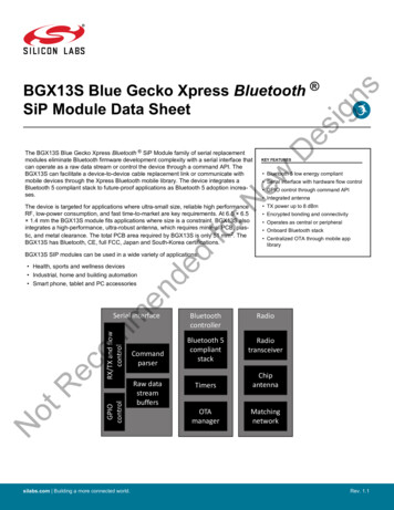
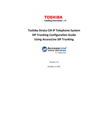
BGM13S Blue Gecko Bluetooth SiP Module Data SheetSystem Overview3. System Overview3.1 IntroductionThe BGM13S product family combines an energy-friendly MCU with a highly integrated radio transceiver and a high performance, ultrarobust antenna. The devices are well suited for any battery operated application, as well as other system where ultra-small size, reliablehigh performance RF, low-power consumption and easy application development are key requirements. This section gives a short introduction to the full radio and MCU system.A detailed block diagram of the BGM13S module is shown in the figure below.Radio TranscieverBALUNMatchingRF RCChipAntennaIOVDDDigital PeripheralsLETIMERTIMERPCNTRTC / RTCC512 KB ISP FlashProgram MemoryEnergy ManagementFloating Point UnitA AH PB BPAVDD / RFVDD / DVDDbypassDC-DCConverterVBATTVREGVDD / AVDDVoltageMonitorWatchdogTimerClock ManagementLFXOInternalReference12-bit ADCAUXHFRCOInternal Crystal38.4 MHz CrystalLFRCOHFRCOHFXOPCnPort DDriversPDnPort FDriversPFnAnalog PeripheralsULFRCOLFXTAL PLFXTAL NPort CDriversIDACVDACVoltageRegulatorPBnCRCLESENSEDMA ControllerIOVDD1V8I2CCRYPTO64 KB RAMMemory Protection UnitPort BDriversOp-AmpVDDAPORTBrown Out /Power-OnResetLEUARTMux & FBDebug Signals(shared w/GPIO)PortMapperUSARTARM Cortex-M4 CoreInput MuxSerial Wireand ETMDebug /ProgrammingResetManagementUnitPAn -RESETnPort ADriversCRYOTIMERRACDEMODBUFCPort I/O RCO Analog ComparatorFigure 3.1. BGM13S Block Diagram3.2 RadioThe BGM13S features a radio transceiver supporting Bluetooth low energy protocol. It features a memory buffer and a low-voltagecircuit that can withstand extremely high data rates.3.2.1 Antenna InterfaceThe BGM13S has two antenna solution variants. One of them is a high-performance integrated chip antenna (BGM13SxxFxxxxA) andthe other is a 50 Ohm matched RF pin to attach an external antenna to the module (BGM13SxxFxxxxN).silabs.com Building a more connected world.Rev. 1.1 7
BGM13S Blue Gecko Bluetooth SiP Module Data SheetSystem OverviewTable 3.1. Antenna Efficiency and Peak GainParameterWith optimal layout NoteEfficiency-1 to -2 dBPeak gain1 dBiAntenna efficiency, gain and radiation pattern are highly dependent on the application PCB layout and mechanical design. Referto for PCB layout and antenna integration guidelines for optimalperformance.3.2.2 RFSENSEThe RFSENSE block generates a system wakeup interrupt upon detection of wideband RF energy at the antenna interface, providingtrue RF wakeup capabilities from low energy modes including EM2, EM3 and EM4.RFSENSE triggers on a relatively strong RF signal and is available in the lowest energy modes, allowing exceptionally low energy consumption. RFSENSE does not demodulate or otherwise qualify the received signal, but software may respond to the wakeup event byenabling normal RF reception.Various strategies for optimizing power consumption and system response time in presence of false alarms may be employed usingavailable timer peripherals.3.2.3 Packet and State TraceThe BGM13S Frame Controller has a packet and state trace unit that provides valuable information during the development phase. Itfeatures: Non-intrusive trace of transmit data, receive data and state information Data observability on a single-pin UART data output, or on a two-pin SPI data output Configurable data output bitrate / baudrate Multiplexed transmitted data, received data and state / meta information in a single serial data stream3.2.4 Random Number GeneratorThe Frame Controller (FRC) implements a random number generator that uses entropy gathered from noise in the RF receive chain.The data is suitable for use in cryptographic applications.Output from the random number generator can be used either directly or as a seed or entropy source for software-based random number generator algorithms such as Fortuna.silabs.com Building a more connected world.Rev. 1.1 8
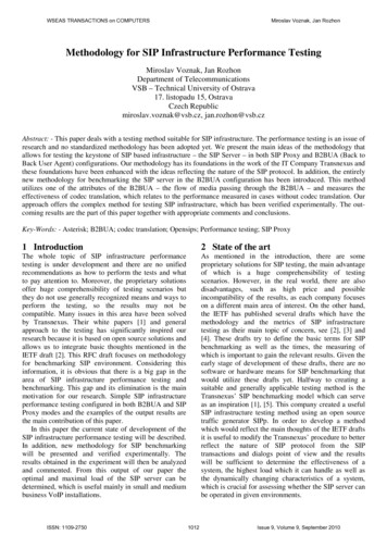
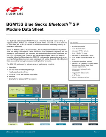
BGM13S Blue Gecko Bluetooth SiP Module Data SheetSystem Overview3.3 PowerThe BGM13S has an Energy Management Unit (EMU) and efficient integrated regulators to generate internal supply voltages. Only asingle external supply voltage is required, from which all internal voltages are created. An integrated DC-DC buck regulator is utilized tofurther reduce the current consumption. Figure 3.2 Power Supply Configuration for BGM13S22xxx Devices on page 9 and Figure3.3 Power Supply Configuration for BGM13S32xxx Devices on page 9 show how the external and internal supplies of the moduleare connected for different part numbers.BGM13S22 ModuleEFR32BG13 SoCIOVDDIOVDDI/O Interfaces220nFRFVDDRFPAVDDRF E2.2µFVREGVDDVBATT4.9µFAVDDAnalogFigure 3.2. Power Supply Configuration for BGM13S22xxx DevicesBGM13S32 ModuleEFR32BG13 SoCIOVDDIOVDDI/O AVDDAnalogRF PAFigure 3.3. Power Supply Configuration for BGM13S32xxx Devicessilabs.com Building a more connected world.Rev. 1.1 9
BGM13S Blue Gecko Bluetooth SiP Module Data SheetSystem Overview3.3.1 Energy Management Unit (EMU)The Energy Management Unit manages transitions of energy modes in the device. Each energy mode defines which peripherals andfeatures are available and the amount of current the device consumes. The EMU can also be used to turn off the power to unused RAMblocks, and it contains control registers for the dc-dc regulator and the Voltage Monitor (VMON). The VMON is used to monitor multiplesupply voltages. It has multiple channels which can be programmed individually by the user to determine if a sensed supply has fallenbelow a chosen threshold.3.3.2 DC-DC ConverterThe DC-DC buck converter covers a wide range of load currents and provides up to 90% efficiency in energy modes EM0, EM1, EM2and EM3. Patented RF noise mitigation allows operation of the DC-DC converter without degrading sensitivity of radio components.Protection features include programmable current limiting, short-circuit protection, and dead-time protection. The DC-DC converter mayalso enter bypass mode when the input voltage is too low for efficient operation. In bypass mode, the DC-DC input supply is internallyconnected directly to its output through a low resistance switch. Bypass mode also supports in-rush current limiting to prevent inputsupply voltage droops due to excessive output current transients.3.3.3 Power DomainsThe BGM13S has two peripheral power domains for operation in EM2 and EM3. If all of the peripherals in a peripheral power domainare configured as unused, the power domain for that group will be powered off in the low-power mode, reducing the overall currentconsumption of the device.Table 3.2. Peripheral Power SubdomainsPeripheral Power Domain 1Peripheral Power Domain EI2C0APORTI2C1-IDAC3.4 General Purpose Input/Output (GPIO)BGM13S has up to 32 General Purpose Input/Output pins. Each GPIO pin can be individually configured as either an output or input.More advanced configurations including open-drain, open-source, and glitch-filtering can be configured for each individual GPIO pin.The GPIO pins can be overridden by peripheral connections, like SPI communication. Each peripheral connection can be routed to several GPIO pins on the device. The input value of a GPIO pin can be routed through the Peripheral Reflex System to other peripherals.The GPIO subsystem supports asynchronous external pin interrupts.3.5 Clocking3.5.1 Clock Management Unit (CMU)The Clock Management Unit controls oscillators and clocks in the BGM13S. Individual enabling and disabling of clocks to all peripherals is performed by the CMU. The CMU also controls enabling and configuration of the oscillators. A high degree of flexibility allowssoftware to optimize energy consumption in any specific application by minimizing power dissipation in unused peripherals and oscillators.silabs.com Building a more connected world.Rev. 1.1 10
BGM13S Blue Gecko Bluetooth SiP Module Data SheetSystem Overview3.5.2 Internal Oscillators and CrystalThe BGM13S fully integrates two crystal oscillators, four RC oscillators, and a 38.4 MHz crystal. The high-frequency crystal oscillator (HFXO) and integrated 38.4 MHz crystal provide a precise timing reference for the MCU andradio. The low-frequency crystal oscillator (LFXO) provides an accurate timing reference for low energy modes and the real-time-clock circuits. An integrated high frequency RC oscillator (HFRCO) is available for the MCU system, when crystal accuracy is not required. TheHFRCO employs fast startup at minimal energy consumption combined with a wide frequency range. An integrated auxilliary high frequency RC oscillator (AUXHFRCO) is available for timing the general-purpose ADC and the SerialWire Viewer port with a wide frequency range. An integrated low frequency 32.768 kHz RC oscillator (LFRCO) for low power operation where high accuracy is not required. An integrated low frequency precision 32.768 kHz RC oscillator (PLFRCO) can be used as a timing reference in low energy modes,with 500 ppm accuracy. An integrated ultra-low frequency 1 kHz RC oscillator (ULFRCO) is available to provide a timing reference at the lowest energy consumption in low energy modes.3.6 Counters/Timers and PWM3.6.1 Timer/Counter (TIMER)TIMER peripherals keep track of timing, count events, generate PWM outputs and trigger timed actions in other peripherals through thePRS system. The core of each TIMER is a 16-bit counter with up to 4 compare/capture channels. Each channel is configurable in oneof three modes. In capture mode, the counter state is stored in a buffer at a selected input event. In compare mode, the channel outputreflects the comparison of the counter to a programmed threshold value. In PWM mode, the TIMER supports generation of pulse-widthmodulation (PWM) outputs of arbitrary waveforms defined by the sequence of values written to the compare registers, with optionaldead-time insertion available in timer unit TIMER 0 only.3.6.2 Wide Timer/Counter (WTIMER)WTIMER peripherals function just as TIMER peripherals, but are 32 bits wide. They keep track of timing, count events, generate PWMoutputs and trigger timed actions in other peripherals through the PRS system. The core of each WTIMER is a 32-bit counter with up to4 compare/capture channels. Each channel is configurable in one of three modes. In capture mode, the counter state is stored in abuffer at a selected input event. In compare mode, the channel output reflects the comparison of the counter to a programmed threshold value. In PWM mode, the WTIMER supports generation of pulse-width modulation (PWM) outputs of arbitrary waveforms defined bythe sequence of values written to the compare registers, with optional dead-time insertion available in timer unit WTIMER 0 only.3.6.3 Real Time Counter and Calendar (RTCC)The Real Time Counter and Calendar (RTCC) is a 32-bit counter providing timekeeping in all energy modes. The RTCC includes aBinary Coded Decimal (BCD) calendar mode for easy time and date keeping. The RTCC can be clocked by any of the on-board oscillators with the exception of the AUXHFRCO, and it is capable of providing system wake-up at user defined instances. When receivingframes, the RTCC value can be used for timestamping. The RTCC includes 128 bytes of general purpose data retention, allowing easyand convenient data storage in all energy modes down to EM4H.A secondary RTC is used by the RF protocol stack for event scheduling, leaving the primary RTCC block available exclusively for application software.3.6.4 Low Energy Timer (LETIMER)The unique LETIMER is a 16-bit timer that is available in energy mode EM2 Deep Sleep in addition to EM1 Sleep and EM0 Active. Thisallows it to be used for timing and output generation when most of the device is powered down, allowing simple tasks to be performedwhile the power consumption of the system is kept at an absolute minimum. The LETIMER can be used to output a variety of waveforms with minimal software intervention. The LETIMER is connected to the Real Time Counter and Calendar (RTCC), and can be configured to start counting on compare matches from the RTCC.3.6.5 Ultra Low Power Wake-up Timer (CRYOTIMER)The CRYOTIMER is a 32-bit counter that is capable of running in all energy modes. It can be clocked by either the 32.768 kHz crystaloscillator (LFXO), the 32.768 kHz RC oscillator (LFRCO), or the 1 kHz RC oscillator (ULFRCO). It can provide periodic Wakeup eventsand PRS signals which can be used to wake up peripherals from any energy mode. The CRYOTIMER provides a wide range of interrupt periods, facilitating flexible ultra-low energy operation.silabs.com Building a more connected world.Rev. 1.1 11
BGM13S Blue Gecko Bluetooth SiP Module Data SheetSystem Overview3.6.6 Pulse Counter (PCNT)The Pulse Counter (PCNT) peripheral can be used for counting pulses on a single input or to decode quadrature encoded inputs. Theclock for PCNT is selectable from either an external source on pin PCTNn S0IN or from an internal timing reference, selectable fromamong any of the internal oscillators, except the AUXHFRCO. The peripheral may operate in energy mode EM0 Active, EM1 Sleep,EM2 Deep Sleep, and EM3 Stop.3.6.7 Watchdog Timer (WDOG)The watchdog timer can act both as an independent watchdog or as a watchdog synchronous with the CPU clock. It has windowedmonitoring capabilities, and can generate a reset or different interrupts depending on the failure mode of the system. The watchdog canalso monitor autonomous systems driven by PRS.3.7 Communications and Other Digital Peripherals3.7.1 Universal Synchronous/Asynchronous Receiver/Transmitter (USART)The Universal Synchronous/Asynchronous Receiver/Transmitter is a flexible serial I/O interface. It supports full duplex asynchronousUART communication with hardware flow control as well as RS-485, SPI, MicroWire and 3-wire. It can also interface with devices supporting: ISO7816 SmartCards IrDA I2S3.7.2 Low Energy Universal Asynchronous Receiver/Transmitter (LEUART)The unique LEUARTTM provides two-way UART communication on a strict power budget. Only a 32.768 kHz clock is needed to allowUART communication up to 9600 baud. The LEUART includes all necessary hardware to make asynchronous serial communicationpossible with a minimum of software intervention and energy consumption.3.7.3 Inter-Integrated Circuit Interface (I2C)The I2C interface enables communication between the MCU and a serial I2C bus. It is capable of acting as both a master and a slaveand supports multi-master buses. Standard-mode, fast-mode and fast-mode plus speeds are supported, allowing transmission ratesfrom 10 kbit/s up to 1 Mbit/s. Slave arbitration and timeouts are also available, allowing implementation of an SMBus-compliant system.The interface provided to software by the I2C peripheral allows precise timing control of the transmission process and highly automatedtransfers. Automatic recognition of slave addresses is provided in active and low energy modes.3.7.4 Peripheral Reflex System (PRS)The Peripheral Reflex System provides a communication network between different peripherals without software involvement. Peripherals producing Reflex signals are called producers. The PRS routes Reflex signals from producers to consumer peripherals, which inturn perform actions in response. Edge triggers and other functionality such as simple logic operations (AND, OR, NOT) can be appliedby the PRS to the signals. The PRS allows peripheral to act autonomously without waking the MCU core, saving power.3.7.5 Low Energy Sensor Interface (LESENSE)The Low Energy Sensor Interface LESENSETM is a highly configurable sensor interface with support for up to 16 individually configurable sensors. By controlling the analog comparators, ADC, and DAC, LESENSE is capable of supporting a wide range of sensors andmeasurement schemes, and can for instance measure LC sensors, resistive sensors and capacitive sensors. LESENSE also includes aprogrammable finite state machine which enables simple processing of measurement results without CPU intervention. LESENSE isavailable in energy mode EM2, in addition to EM0 and EM1, making it ideal for sensor monitoring in applications with a strict energybudget.3.8 Security Features3.8.1 General Purpose Cyclic R
2 16-bit Timer/Counter 3 or 4 Compare/Capture/PWM channels 1 32-bit Timer/Counter 3 Compare/Capture/PWM channels Precision Low Frequency RC Oscillator (PLFRCO) 32-bit Real Time Counter and Calendar 16-bit Low Energy Timer for waveform generation 32-bit Ultra Low Energy Timer/Counter for periodic wake-up