Transcription
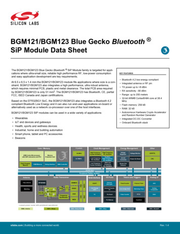
KEY FEATURESNewThe BGX13S Blue Gecko Xpress Bluetooth SiP Module family of serial replacementmodules eliminate Bluetooth firmware development complexity with a serial interface thatcan operate as a raw data stream or control the device through a command API. TheBGX13S can facilitate a device-to-device cable replacement link or communicate withmobile devices through the Xpress Bluetooth mobile library. The device integrates aBluetooth 5 compliant stack to future-proof applications as Bluetooth 5 adoption increases.DesignsBGX13S Blue Gecko Xpress Bluetooth SiP Module Data SheetforThe device is targeted for applications where ultra-small size, reliable high performanceRF, low-power consumption, and fast time-to-market are key requirements. At 6.5 6.5 1.4 mm the BGX13S module fits applications where size is a constraint. BGX13S alsointegrates a high-performance, ultra-robust antenna, which requires minimal PCB, plastic, and metal clearance. The total PCB area required by BGX13S is only 51 mm2. TheBGX13S has Bluetooth, CE, full FCC, Japan and South-Korea certifications. Bluetooth 5 low energy compliant Serial interface with hardware flow control GPIO control through command API Integrated antenna TX power up to 8 dBm Encrypted bonding and connectivity Operates as central or peripheral Onboard Bluetooth stack Centralized OTA through mobile applibrarymendedBGX13S SIP modules can be used in a wide variety of applications: Health, sports and wellness devices Industrial, home and building automation Smart phone, tablet and PC accessoriesGPIOcontrolNotRecRX/TX and flowcontrolomSerial interfacesilabs.com Building a more connected world.CommandparserRaw datastreambuffersBluetoothcontrollerRadioBluetooth AmanagerMatchingnetworkRev. 1.1
BGX13S Blue Gecko Xpress Bluetooth SiP Module Data SheetOrdering Information1. Ordering InformationTable 1.1. Ordering InformationFrequency BandProtocol Stack@ Max TX PowerAntennaGPIOPackagingBGX13S22GA-V31RBluetooth LowEnergy2.4 GHz @ 8 dBmBuilt-in8ReelBGX13S22GA-V31Bluetooth LowEnergy2.4 GHz @ 8 g Codesilabs.com Building a more connected world.Rev. 1.1 2
Table of Contents1. Ordering Information . . . . . . . . . . . . . . . . . . . . . . . . . . . . 22. Electrical Specifications . . . . . . . . . . . . . . . . . . . . . . . . . . . 5. 5. 5. 6. 7. 8.12.13. . . . . . . . . . . . . . . . . . . . . . . . 153.1 Typical BGX13S Connections .15. . . . . . . . . . . . . . . . . . . . . . . . . . . . 164.1 Layout Guidelines .4.2 Effect of PCB Width .4.3 Effect of Plastic and Metal Materials .4.4 Effects of Human Body .New4. Layout Guidelines.D3. Typical Connection Diagrams.esigns2.1 Electrical Characteristics . . . . . .2.1.1 Absolute Maximum Ratings . . . .2.1.2 Operating Conditions . . . . . .2.1.3 Power Consumption. . . . . . .2.1.4 2.4 GHz RF Transceiver Characteristics2.1.5 Non-Volatile Configuration Storage. .2.1.6 General-Purpose I/O (GPIO) . . . .16.17.17.184.5 2D Radiation Pattern Plots .18for.mended5. Pin Definitions . . . . . . . . . . . . . . . . . . . . . . . . . . . . . . 20.24.246.7 Device Configuration .246.8 Security Features .246.9 OTA.246.10 Direct Test Mode Support .245.1 BGX13S Device Pinout .6. Functional Overview.20. . . . . . . . . . . . . . . . . . . . . . . . . . .23.236.2 Communication Use Cases .236.3 Embedded Interface .236.4 Command Mode and Streaming Mode .236.5 Command API .om6.1 Introduction .ec6.6 GPIO ControlR.Not7. Package Specifications. . . . . . . . . . . . . . . . . . . . . . . . . . 257.1 BGX13S Package Dimensions.257.2 BGX13S Recommeded PCB Land Pattern.287.3 BGX13S Package Marking .31.8. Tape and Reel Specifications8.1 Tape and Reel Packaging .silabs.com Building a more connected world. . . . . . . . . . . . . . . . . . . . . . . . 32.32Rev. 1.1 3
8.2 Reel and Tape Specifications .328.3 Orientation and Tape Feed .348.4 Tape and Reel Box Dimensions .348.5 Moisture Sensitivity Level .34. . . . . . . . . . . . . . . . . . . . . . . . 359.1 Soldering Recommendations .esigns9. Soldering Recommendations.3510. Certifications . . . . . . . . . . . . . . . . . . . . . . . . . . . . . . 36.10.2 Bluetooth .10.3 CE.36.36.36.10.4 FCC .3710.5 ISED Canada .3810.6 Japan.10.7 KC (South-Korea).40.4011. Revision History. . . . . . . . . . . . . . . . . . . . . . . . . . . . .41NotRecommendedfor.D.New10.1 Qualified Antenna Types .silabs.com Building a more connected world.Rev. 1.1 4
BGX13S Blue Gecko Xpress Bluetooth SiP Module Data SheetElectrical Specifications2. Electrical Specifications2.1 Electrical CharacteristicsAll electrical parameters in all tables are specified under the following conditions, unless stated otherwise: Typical values are based on TAMB 25 C and VBAT 3.3 V, by production test and/or technology characterization.esigns Radio performance numbers are measured in conducted mode, based on Silicon Laboratories reference designs using output power-specific external RF impedance-matching networks for interfacing to a 50 Ω antenna. Minimum and maximum values represent the worst conditions across supply voltage, process variation, and operating temperature,unless stated otherwise.Refer to for more details about operational supply and temperature limits.2.1.1 Absolute Maximum RatingsNewDStresses above those listed below may cause permanent damage to the device. This is a stress rating only and functional operation ofthe devices at those or any other conditions above those indicated in the operation listings of this specification is not implied. Exposureto maximum rating conditions for extended periods may affect device reliability. For more information on the available quality and reliability data, see the Quality and Reliability Monitor Report at t.aspx.Table 2.1. Absolute Maximum RatingsStorage temperature rangeTSTGVoltage on any supply pinVDDMAXVoltage ramp rate on anysupply pinVDDRAMPMAXDC voltage on any GPIO pinVDIGPINMaximum RF level at inputPRFMAX2G4Test ��85 C-0.3—3.8V——1V / µs-0.3—IOVDD 0.3V——10dBmSource——200mATotal current into VSSground linesIVSSMAXSink——200mACurrent per I/O 00mASource——200mA-40—105 ComTotal current into supply pins IVDDMAXCurrent for all I/O pinsTJNotRecJunction temperatureIIOALLMAXsilabs.com Building a more connected world.Rev. 1.1 5
BGX13S Blue Gecko Xpress Bluetooth SiP Module Data SheetElectrical Specifications2.1.2 Operating ConditionsThe following subsections define the operating conditions for the module.ParameterSymbolTest ConditionOperating ambient temperature rangeTA-40VBATT operating supplyvoltageVVBATT2.4VBATT currentIVBATT—1.62TypMaxUnit2585 D operating supply volt- VIOVDDageMinDTable 2.2. General Operating Conditionsesigns2.1.2.1 General Operating Conditionssilabs.com Building a more connected world.Rev. 1.1 6
BGX13S Blue Gecko Xpress Bluetooth SiP Module Data SheetElectrical Specifications2.1.3 Power ConsumptionUnless otherwise indicated, typical conditions are: VBATT 3.3 V. T 25 C. Minimum and maximum values in this table represent theworst conditions across process variation at T 25 C.Table 2.3. Power ConsumptionTest ConditionActive supply current, Unconnected, IdleIACTIVE IDLEBaud rate 9600 bps—Baud rate 9600 bps—Interval 546.25 ms, Baud rate 9600 bps—Interval 20 ms, Baud rate 9600 bps—Interval 546.25 ms, Baud rate 9600 bpsIACTIVE terval 20 ms, Baud rate 9600 bps—4.7—mAIdle, Baud Rate 9600 bps—660—µATX/RX (acknowledged) at highestthroughput, Baud Rate 9600bps—3.5—mATX/RX (unacknowledged) at highest throughput, Baud Rate 9600bps—4—mAIdle, Baud Rate 9600 bps—3.5—mATX/RX (acknowledged) at highestthroughput, Baud Rate 9600bps—5.25—mATX/RX (unacknowledged) at highest throughput, Baud Rate 9600bps—7—mARadio disabled—3—µARadio enabled, Advertising, Interval 546.25 ms—90—µARadio enabled, Advertising, Interval 20 ms—2—mAmendedILPMNotRecomSupply current in low powermodeMax3forActive supply current, Connected, 15 ms IntervalTypNewActive supply current, Adver- IACTIVE ADVtisingMinesignsSymbolDParametersilabs.com Building a more connected world.Rev. 1.1 7
BGX13S Blue Gecko Xpress Bluetooth SiP Module Data SheetElectrical Specifications2.1.4 2.4 GHz RF Transceiver Characteristics2.1.4.1 RF Transmitter General Characteristics for 2.4 GHz BandUnless otherwise indicated, typical conditions are: T 25 C, VBATT 3.3 V. DC-DC on. Crystal frequency 38.4 MHz. RF centerfrequency 2.45 GHz. Conducted measurement from the antenna feedpoint.Test ConditionSymbolMaximum TX power1POUTMAXMinimum active TX PowerPOUTMINCWOutput power step sizePOUTSTEP-5 dBm Output power 0 dBm—0 dBm output power POUTMAX2.4 V VVBATT 3.3 VOutput power variation vstemperature at POUTMAXPOUTVAR TFrom -40 to 85 COver RF tuning frequency .5MHzNewPOUTVAR VRF tuning frequency rangeMin—Output power variation vssupply at POUTMAXOutput power variation vs RF POUTVAR Ffrequency at POUTMAXTypDParameteresignsTable 2.4. RF Transmitter General Characteristics for 2.4 GHz BandNotRecommendedNote:1. Supported transmit power levels are determined by the ordering part number (OPN). Transmit power ratings for all devices covered in this datasheet can be found in the Max TX Power column of the Ordering Information Table.silabs.com Building a more connected world.Rev. 1.1 8
BGX13S Blue Gecko Xpress Bluetooth SiP Module Data SheetElectrical Specifications2.1.4.2 RF Receiver General Characteristics for 2.4 GHz BandUnless otherwise indicated, typical conditions are: T 25 C, VBATT 3.3 V. DC-DC on. Crystal frequency 38.4 MHz. RF centerfrequency 2.45 GHz. Conducted measurement from the antenna feedpoint.Table 2.5. RF Receiver General Characteristics for 2.4 GHz BandRF tuning frequency rangeFRANGEReceive mode maximumspurious emissionSPURRXTest ConditionMin2400—1 GHz to 12 GHz—Max spurious emissions dur- SPURRX FCCing active receive mode, perFCC Part 15.109(a)216 MHz to 960 MHz, ConductedMeasurement—Above 960 MHz, ConductedMeasurement—Level above whichRFSENSE will trigger1RFSENSETRIGCW at 2.45 GHz—Level below whichRFSENSE will not trigger1RFSENSETHRES CW at 2.45 �dBm-47.2—dBm-24—dBm-50—dBmNew30 MHz to 1 1. RFSENSE performance is only valid from 0 to 85 C. RFSENSE should be disabled outside this temperature range.silabs.com Building a more connected world.Rev. 1.1 9
BGX13S Blue Gecko Xpress Bluetooth SiP Module Data SheetElectrical Specifications2.1.4.3 RF Receiver Characteristics for Bluetooth Low Energy in the 2.4GHz Band, 1 Mbps Data RateUnless otherwise indicated, typical conditions are: T 25 C, VBATT 3.3 V. DC-DC on. Crystal frequency 38.4 MHz. RF centerfrequency 2.45 GHz. Conducted measurement from the antenna feedpoint.Table 2.6. RF Receiver Characteristics for Bluetooth Low Energy in the 2.4GHz Band, 1 Mbps Data RateTest ConditionMinMax usable receiver inputlevel, 0.1% BERSATSignal is reference signal1. Packetlength is 20 bytes.—Sensitivity, 0.1% BERSENSSignal is reference signal1. UsingDC-DC converter.—With non-ideal signals as specified in RF-PHY.TS.4.2.2, section4.6.1.—Signal to co-channel interfer- C/ICCer, 0.1% BERDesired signal 3 dB above reference sensitivity.—N 1 adjacent channel selec- C/I1 tivity, 0.1% BER, with allowable exceptions. Desired isreference signal at -67 dBmInterferer is reference signal at 1MHz offset. Desired frequency2402 MHz Fc 2480 MHz—N-1 adjacent channel selec- C/I1tivity, 0.1% BER, with allowable exceptions. Desired isreference signal at -67 dBmInterferer is reference signal at -1MHz offset. Desired frequency2402 MHz Fc 2480 MHzAlternate selectivity, 0.1%BER, with allowable exceptions. Desired is referencesignal at -67 dBmC/I2Alternate selectivity, 0.1%BER, with allowable exceptions. Desired is referencesignal at -67 ferer is reference signal at 2MHz offset. Desired frequency2402 MHz Fc 2480 MHz—-42.0—dBInterferer is reference signal at 3MHz offset. Desired frequency2404 MHz Fc 2480 MHz—-46.4—dBSelectivity to image frequen- C/IIMcy, 0.1% BER. Desired is reference signal at -67 dBmInterferer is reference signal at image frequency with 1 MHz precision—-42.0—dBSelectivity to image frequency 1 MHz, 0.1% BER. Desired is reference signal at-67 dBmInterferer is reference signal at image frequency 1 MHz with 1MHz precision—-47.1—dBPer Core 4.1, Vol 6, Part A, Section 4.4 with n 3—-18.4—dBmNewformendedecomC/IIM 1Intermodulation performance IM9.0NotRNote:1. Reference signal is defined 2GFSK at -67 dBm, Modulation index 0.5, BT 0.5, Bit rate 1 Mbps, desired data PRBS9;interferer data PRBS15; frequency accuracy better than 1 ppm.silabs.com Building a more connected world.Rev. 1.1 10
BGX13S Blue Gecko Xpress Bluetooth SiP Module Data SheetElectrical Specifications2.1.4.4 RF Receiver Characteristics for Bluetooth Low Energy in the 2.4GHz Band, 2 Mbps Data RateUnless otherwise indicated, typical conditions are: T 25 C, VBATT 3.3 V. DC-DC on. Crystal frequency 38.4 MHz. RF centerfrequency 2.45 GHz. Conducted measurement from the antenna feedpoint.Table 2.7. RF Receiver Characteristics for Bluetooth Low Energy in the 2.4GHz Band, 2 Mbps Data RateTest ConditionMinMax usable receiver inputlevel, 0.1% BERSATSignal is reference signal1. Packetlength is 20 bytes.—Sensitivity, 0.1% BERSENSSignal is reference signal1. UsingDC-DC converter.—With non-ideal signals as specified in RF-PHY.TS.4.2.2, section4.6.1.—Signal to co-channel interfer- C/ICCer, 0.1% BERDesired signal 3 dB above reference sensitivity.—N 1 adjacent channel selec- C/I1 tivity, 0.1% BER, with allowable exceptions. Desired isreference signal at -67 dBmInterferer is reference signal at 2MHz offset. Desired frequency2402 MHz Fc 2480 MHz—N-1 adjacent channel selec- C/I1tivity, 0.1% BER, with allowable exceptions. Desired isreference signal at -67 dBmInterferer is reference signal at -2MHz offset. Desired frequency2402 MHz Fc 2480 MHzAlternate selectivity, 0.1%BER, with allowable exceptions. Desired is referencesignal at -67 dBmC/I2Alternate selectivity, 0.1%BER, with allowable exceptions. Desired is referencesignal at -67 rferer is reference signal at 4MHz offset. Desired frequency2402 MHz Fc 2480 MHz—-40.3—dBInterferer is reference signal at 6MHz offset. Desired frequency2404 MHz Fc 2480 MHz—-45.1—dBSelectivity to image frequen- C/IIMcy, 0.1% BER. Desired is reference signal at -67 dBmInterferer is reference signal at image frequency with 1 MHz precision—-7.6—dBSelectivity to image frequency 2 MHz, 0.1% BER. Desired is reference signal at-67 dBmInterferer is reference signal at image frequency 2 MHz with 2MHz precision—-40.30—dBPer Core 4.1, Vol 6, Part A, Section 4.4 with n 3—-18.4—dBmNewformendedecomC/IIM 1Intermodulation performance IM8.6NotRNote:1. Reference signal is defined 2GFSK at -67 dBm, Modulation index 0.5, BT 0.5, Bit rate 2 Mbps, desired data PRBS9;interferer data PRBS15; frequency accuracy better than 1 ppm.silabs.com Building a more connected world.Rev. 1.1 11
BGX13S Blue Gecko Xpress Bluetooth SiP Module Data SheetElectrical Specifications2.1.5 Non-Volatile Configuration StorageTable 2.8. Non-Volatile Configuration StorageUpdate cycles before failureData retentionTest ��yearsSupply voltage during update metersilabs.com Building a more connected world.Rev. 1.1 12
BGX13S Blue Gecko Xpress Bluetooth SiP Module Data SheetElectrical Specifications2.1.6 General-Purpose I/O (GPIO)Table 2.9. General-Purpose I/O (GPIO)SymbolTest ConditionMinTypMaxUnitInput low voltage1VILGPIO pins——IOVDD*0.3VInput high voltage1VIHGPIO pinsIOVDD*0.7——VOutput high voltage relativeto IOVDDVOHSourcing 3 mA, IOVDD 3 V,IOVDD*0.8——V——V—VDrive Strength WeakIOVDD*0.6DSourcing 1.2 mA, IOVDD 1.62V,Drive Strength WeakDrive Strength StrongSourcing 8 mA, IOVDD 1.62 .4V——IOVDD*0.2V——IOVDD*0.4VAll GPIO except LFXO pins, GPIO IOVDD—0.130nALFXO Pins, GPIO —ns—2.2—ns—7.4—nsDrive Strength StrongSinking 3 mA, IOVDD 3 V,forOutput low voltage relative to VOLIOVDDIOVDD*0.8NewSourcing 20 mA, IOVDD 3 V,esignsParameterDrive Strength WeakSinking 1.2 mA, IOVDD 1.62 V,mendedDrive Strength WeakSinking 20 mA, IOVDD 3 V,Drive Strength StrongSinking 8 mA, IOVDD 1.62 V,Drive Strength StrongIIOLEAKomInput leakage currentI/O pin pull-up/pull-down resistor2RPUDecPulse width of pulses retIOGLITCHmoved by the glitch suppression filterNotROutput fall time, From 70%to 30% of VIOOutput rise time, From 30%to 70% of VIOtIOOFCL 50 pF,Drive Strength StrongCL 50 pF,Drive Strength WeaktIOORCL 50 pF,Drive Strength StrongCL 50 pF,Drive Strength Weaksilabs.com Building a more connected world.Rev. 1.1 13
BGX13S Blue Gecko Xpress Bluetooth SiP Module Data SheetElectrical SpecificationsParameterSymbolTest ote:1. GPIO input threshold are proportional to the IOVDD supply, except for RESETn which is proportional to VBATT.2. GPIO pull-ups are referenced to the IOVDD supply, except for RESETn, which connects to VBATT.silabs.com Building a more connected world.Rev. 1.1 14
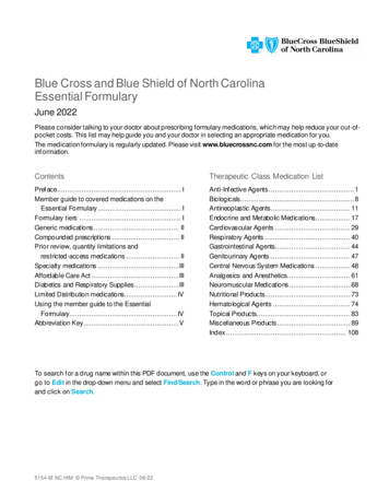
BGX13S Blue Gecko Xpress Bluetooth SiP Module Data SheetTypical Connection Diagrams3. Typical Connection Diagrams3.1 Typical BGX13S ConnectionsTypical connections for the BGX13S module are shown in Figure 3.1 Typical Connections for BGX13S on page 15. This diagramshows connections for: Power suppliesesignsNote: The 1V8 pin is the 1.8V output of the internal DC-DC converer. This pin should be left unconnected. Do not add external decoupling or power external circuits from this pin.Note:It is recommended to connect the RESETn line to an open-drain IO pin on the host CPU.D Antenna loop for internal antenna usage or external antenna connection - The RF and ANTENNA pins should be tied together forcorrect operation of the module. An optional 0R resistor can be added between RF and ANTENNA, making it possible to measurethe signal between these pins. Reset lineNewRESETn includes an internal pull-up to the VBATT supply and input logic levels on RESETn are referenced to VBATT. In systemswhere IOVDD is not equal to VBATT, additional considerations may need to be taken. UART connection to an embedded host Optional 32.768 kHz crystal - Recommended crystal is KDS part number 1TJG125DP1A0012 or equivalent. Crystal used must havebetter than 100 ppm accuracy.forNote:If external low-frequency crystal is unused, LFXTAL pins must be tied to ground - ground connections are detected by device andinternal oscillator is used instead.NotRecIOVDDBattery or IO4GPIO5GPIO6GPIO7UART TXUART RXUART CTSUART RTSRXTXRTSCTSBGX13SLFXTAL PLFXTAL NHost CPUVSSR1 (0R)omUse 0R to connect theantenna to the RF output1V8Inductor or capacitorfor antenna fine tuningVSS(optional)VBATTBattery / Supply VoltageVDDmended Optional BOOT pin connection - BOOT is an active-low digital input that will force the module into a DFU bootloader state after device reset. BOOT can be tied to IOVDD or left disconnected if it is unused.(optional)32.768 kHz XTALBOOTFigure 3.1. Typical Connections for BGX13Ssilabs.com Building a more connected world.Rev. 1.1 15
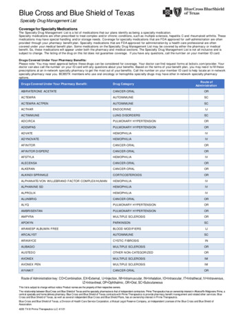
BGX13S Blue Gecko Xpress Bluetooth SiP Module Data SheetLayout Guidelines4. Layout GuidelinesFor optimal performance of the BGX13S, please follow the PCB layout guidelines and ground plane recommendations indicated in thissection.4.1 Layout GuidelinesNewDesignsThis section contains generic PCB layout and design guidelines for the BGX13S module. For optimal performance: Place the module at the edge of the PCB, as shown in the figures in this chapter. Do not place any metal (traces, components, etc.) in the antenna clearance area. Connect all ground pads directly to a solid ground plane. Place the ground vias as close to the ground pads as possible.The following rules are recommended for the PCB design: Trace to copper clearance 150um PTH drill size 300um PTH annular ring 150ummendedImportant:forFigure 4.1. BGX13S PCB Top Layer DesignThe antenna area must align with the pads precisely. Please refer to the recommended PCB land pattern for exact dimensions.NotRecomFigure 4.2. BGX13S PCB Middle and Bottom Layer DesignFigure 4.3. Practical Installation of BGX13S on Application PCBsilabs.com Building a more connected world.Rev. 1.1 16
BGX13S Blue Gecko Xpress Bluetooth SiP Module Data SheetDFigure 4.4. Poor Layout Designs for the BGX13SesignsLayout GuidelinesNewLayout checklist for BGX13S:1. Antenna area is aligned relative to the module pads as shown in the recommended PCB land pattern.2. Clearance area within the inner layers and bottom layer is covering the whole antenna area as shown in the layout guidelines.3. The antenna loop is implemented on the top layer as shown in the layout guidelines.4. All dimensions within the antenna area are precisely as shown in the recommended PCB land pattern.5. The module is placed near the edge of the PCB with max 1mm indentation.6. The module is not placed in the corner of the PCB.for4.2 Effect of PCB WidthommendedThe BGX13S module should be placed at the center of the PCB edge. The width of the board has an impact to the radiated efficiencyand, more importantly, there should be enough ground plane on both sides of the module for optimal antenna performance. Figure4.5 BGX13S PCB Top Layer Design on page 17 gives an indication of ground plane size vs. maximum achievable range.Figure 4.5. BGX13S PCB Top Layer DesignecThe impact of the board size to the radiated performance is a generic feature of all PCB and chip antennas and it is not a unique feature of the BGX13S. For the BGX13S the depth of the board is not important and does not impact the radiated performance.R4.3 Effect of Plastic and Metal MaterialsNotThe antenna on the BGX13S is insensitive to the effects of nearby plastic and other materials with low dielectric constant. No separation between the BGX13S and plastic or other materials is needed. The board thickness has an impact on the module and the additional inductor/capacitor will help to tune the antenna to any board thickness.In some cases, it may be necessary to fine tune the antenna to optimize for any specific application layout or mechanical design. Acapacitor or an inductor in parallel with the antenna input can be used for optimizing the antenna for any PCB layouts. A capacitormoves the antenna frequency lower and an inductor moves the antenna frequency higher. Capacitor values between 0.1 pF-10 pF andinductor values 3.6 nH-10 nH can be used.The antenna is extremely robust against any objects in close proximity or in direct contact with the antenna and it is recommended notto adjust the dimensions of the antenna area unless it is clear that a metal object, such as a coin cell battery, within the antenna area isdetuning the antenna.silabs.com Building a more connected world.Rev. 1.1 17
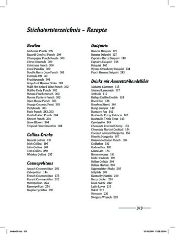
BGX13S Blue Gecko Xpress Bluetooth SiP Module Data SheetLayout Guidelines4.4 Effects of Human BodyPlacing the module in contact with or very close to the human body will negatively impact antenna efficiency and reduce range.forNewDesigns4.5 2D Radiation Pattern PlotsNotRecommendedFigure 4.6. Typical 2D Radiation Pattern – Front ViewFigure 4.7. Typical 2D Radiation Pattern – Side Viewsilabs.com Building a more connected world.Rev. 1.1 18
BGX13S Blue Gecko Xpress Bluetooth SiP Module Data SheetNewDesignsLayout GuidelinesNotRecommendedforFigure 4.8. Typical 2D Radiation Pattern – Top Viewsilabs.com Building a more connected world.Rev. 1.1 19
BGX13S Blue Gecko Xpress Bluetooth SiP Module Data SheetPin Definitions5. Pin DefinitionsommendedforNewDesigns5.1 BGX13S Device PinoutFigure 5.1. BGX13S Device PinoutNotRecThe following table provides package pin connections and general descriptions of pin functionality.silabs.com Building a more connected world.Rev. 1.1 20
BGX13S Blue Gecko Xpress Bluetooth SiP Module Data SheetPin DefinitionsTable 5.1. BGX13S Device PinoutPin NamePin(s)DescriptionGroundRF350 Ohm I/O for external antenna connection.GPIO010Pin with input/output functionality configured by the command API.GPIO111Pin with input/output functionality configured by the command API.GPIO212Pin with input/output functionality configured by the command API.GPIO317Pin with input/output functionality configured by the command API.GPIO418Pin with input/output functionality configured by the command API.GPIO526Pin with input/output functionality configured by the command API.GPIO627Pin with input/output functionality configured by the command API.UART TX13Digital outputUART RX14Digital input15Digital input16Digital output28Pin with input/output functionality configured by the command API.22Battery supply voltage input to the internal DC-DC and analog supply.24Digital IO power supply.19Low frequency external oscillator output pin.UART RTSGPI07VBATTIOVDDDNewfor21Low frequency external oscillator input pin.RESETn44Reset input, active low. To apply an external reset source to this pin, it is requiredto only drive this pin low during reset, and let the internal pull-up ensure that resetis released.ANTENNA250 Ohm input, pin for internal 2.4 GHz antenna231.8V output of the internal DC-DC converer. Do not add external decoupling orpower external circuits from this pin.BOOT33Active-low digital input to force module entrance into DFU bootloader state upondevice reset. See command API documentation for functional details.ANT GND47Antenna ground.ecLFXTAL NRomLFXTAL PmendedUART CTSesignsVSS1452031454648495051Not1V8silabs.com Building a more connected world.Rev. 1.1 21
BGX13S Blue Gecko Xpress Bluetooth SiP Module Data 0414243No Connect.DPin NameesignsPin DefinitionsNotRecommendedforNewNote: Pins labeled N/C (No Connect) and any unused GPIO pins should be left disconnected. UART flow control pins may also be leftdisconnected when feature is unused.silabs.com Building a more connected world.Rev. 1.1 22
BGX13S Blue Gecko Xpress Bluetooth SiP Module Data SheetFunctional Overview6. Functional Overview6.1 IntroductionesignsThe BGX13S creates a Bluetooth 5 compliant Bluetooth Low Energy cable replacement interface, facilitating a Bluetooth Low Energylink to a second embedded device or a mobile device. An embedded MCU controls the device and communicates across the BluetoothLow Energy link through a serial interface and control signals. Parameters stored in non-volatile memory and configurable through theserial interface adjust performance characteristics of the device. Silicon Labs offers iOS and Android mobile libraries for Blue GeckoXpress devices to speed mobile development and simplify communication with the device. This library also controls OTA management,facilitating secure and reliable updates to the device’s embedded stack.6.2 Communication Use CasesThe BGX13S family facilitates two types of Bluetooth Low Energy communication links: BGX-to-mobile BGX-to-BGXDThis functional overview does not cover each command supported by the command API. The complete command API specification isavailable at https://docs.silabs.com/bgx/latest/NewIn the BGX-to-mobile communication use case, the BGX13S operates as a peripheral that is discoverable and connectable when configured to that state through either the command API or the pin states driven by the embedded MCU. Using the Xpress mobile library,mobile applications can scan for BGX13S devices, connect, and communicate with the device in both streaming and remote commandmodes, where the mobile app can execute command API functions remotely.forIn the BGX-to-BGX communication use case, one BGX13S must be configured as the central device and one or more other BGX devices should be configured as a peripheral. Devices can be configured at runtime through the command API, or those settings can besaved to non-volatile memory so that each device wakes from power-on or low power states as either a peripheral or central. For moreinformation on advertising and connection options, please see the command API documentation.6
mobile devices through the Xpress Bluetooth mobile library. The device integrates a Bluetooth 5 compliant stack to future-proof applications as Bluetooth 5 adoption increa-ses. The device is targeted for applications where ultra-small size, reliable high performance RF, low-power consumption, and fast time-to-market are key requirements. At 6.5 .