Transcription
User ManualOriginal InstructionsMicro800 Plug-in ModulesCatalog Numbers 2080-IQ4, 2080-IQ4OB4, 2080-IQ4OV4, 2080-OB4, 2080-OV4, 2080-OW4I, 2080-IF2, 2080-IF4, 2080-OF2,2080-TC2, 2080-RTD2, 2080-MEMBAK-RTC, 2080-MEMBAK-RTC2, 2080-TRIMPOT6, 2080-SERIALISOL, 2080-DNET20, 2080MOT-HSC
Important User InformationRead this document and the documents listed in the additional resources section about installation, configuration, andoperation of this equipment before you install, configure, operate, or maintain this product. Users are required tofamiliarize themselves with installation and wiring instructions in addition to requirements of all applicable codes, laws,and standards.Activities including installation, adjustments, putting into service, use, assembly, disassembly, and maintenance arerequired to be carried out by suitably trained personnel in accordance with applicable code of practice.If this equipment is used in a manner not specified by the manufacturer, the protection provided by the equipment maybe impaired.In no event will Rockwell Automation, Inc. be responsible or liable for indirect or consequential damages resulting fromthe use or application of this equipment.The examples and diagrams in this manual are included solely for illustrative purposes. Because of the many variables andrequirements associated with any particular installation, Rockwell Automation, Inc. cannot assume responsibility orliability for actual use based on the examples and diagrams.No patent liability is assumed by Rockwell Automation, Inc. with respect to use of information, circuits, equipment, orsoftware described in this manual.Reproduction of the contents of this manual, in whole or in part, without written permission of Rockwell Automation,Inc., is prohibitedThroughout this manual, when necessary, we use notes to make you aware of safety considerations.WARNING: Identifies information about practices or circumstances that can cause an explosion in a hazardousenvironment, which may lead to personal injury or death, property damage, or economic loss.ATTENTION: Identifies information about practices or circumstances that can lead to personal injury or death, propertydamage, or economic loss. Attentions help you identify a hazard, avoid a hazard, and recognize the consequence.IMPORTANTIdentifies information that is critical for successful application and understanding of the product.Labels may also be on or inside the equipment to provide specific precautions.SHOCK HAZARD: Labels may be on or inside the equipment, for example, a drive or motor, to alert people that dangerousvoltage may be present.BURN HAZARD: Labels may be on or inside the equipment, for example, a drive or motor, to alert people that surfaces mayreach dangerous temperatures.ARC FLASH HAZARD: Labels may be on or inside the equipment, for example, a motor control center, to alert people topotential Arc Flash. Arc Flash will cause severe injury or death. Wear proper Personal Protective Equipment (PPE). Follow ALLRegulatory requirements for safe work practices and for Personal Protective Equipment (PPE).
PrefaceRead this preface to familiarize yourself with the rest of the manual. It providesinformation concerning: who should use this manual the purpose of this manual related documentation supporting information for Micro800 plug-in modules and accessoriesWho Should Use thisManualUse this manual if you are responsible for designing, installing, programming, ortroubleshooting control systems that use Micro800 controllers.You should have a basic understanding of electrical circuitry and familiarity withrelay logic. If you do not, obtain the proper training before using this product.Purpose of this ManualThis manual is a reference guide for Micro800 controllers, plug-in modules andaccessories. It describes the procedures you use to install, wire, and troubleshootyour controller. This manual: explains how to install and wire your plug-ins gives you an overview of the Micro800 plug-in modules and accessoriesRefer to the additional resources for more information on other element of theMicro800 system.Conformal Coated CatalogsCatalog numbers with the suffix ‘K’ are conformal coated and their specificationsare the same as non-conformal coated catalogs.Additional ResourcesThese documents contain additional information concerning related RockwellAutomation products.ResourceDescriptionMicro820 Programmable Controllers InstallationInstructions, publication 2080-IN009Information on mounting and wiring theMicro820 20-point controllers.Micro830 Programmable Controllers InstallationInstructions, publication 2080-IN002Information on mounting and wiring theMicro830 10-point controllers.Micro830 Programmable Controllers InstallationInstructions, publication 2080-IN003Information on mounting and wiring theMicro830 16-point controllers.Micro830 Programmable Controllers InstallationInstructions, publication, 2080-IN004Information on mounting and wiring theMicro830 24-point controllers.Micro830 Programmable Controllers InstallationInstructions, publication 2080-IN005Information on mounting and wiring theMicro830 48-point controllers.Micro850 Programmable Controllers InstallationInstructions, publication, 2080-IN007Information on mounting and wiring theMicro850 24-point controllers.Rockwell Automation Publication 2080-UM004D-EN-E - March 2018iii
PrefaceivResourceDescriptionMicro850 Programmable Controllers InstallationInstructions, publication 2080-IN008Information on mounting and wiring theMicro850 48-point controllers.Micro870 Programmable Controllers InstallationInstructions, publication 2080-IN008Information on mounting and wiring theMicro870 24-point controllers.Micro820 Programmable Controller UserManual, publication 2080-UM005Information on features, installation, wiring andusage of the Micro820 controllers.Micro830, Micro850, and Micro870Programmable Controllers User Manual,publication 2080-UM002Information on features, installation, wiring andusage of your Micro830, Micro850, andMicro870 programmable controllers.Micro800 Programmable Controller External ACPower Supply Installation Instructions,publication 2080-IN001Information on mounting and wiring the optionalexternal power supply.Micro800 Remote LCD Installation Instructions,publication 2080-IN010Information on mounting and wiring theMicro800 Remote LCD module.Micro800 RS232/485 Isolated Serial PortPlug-in Module Wiring Diagrams,publication 2080-WD002Information on mounting and wiring theMicro800 RS232/485 isolated serial portplug-in module.Micro800 Non-isolated Unipolar Analog InputPlug-in Module Wiring Diagrams,publication 2080-WD003Information on mounting and wiring theMicro800 non-isolated unipolar analog inputplug-in module.Micro800 Non-isolated Unipolar Analog OutputPlug-in Module Wiring Diagrams,publication 2080-WD004Information on mounting and wiring theMicro800 non-isolated unipolar analog outputplug-in module.Micro800 Non-isolated RTD Plug-in ModuleWiring Diagrams, publication 2080-WD005Information on mounting and wiring theMicro800 non-isolated RTD plug-in module.Micro800 Non-isolated ThermocouplePlug-in Module Wiring Diagrams,publication 2080-WD006Information on mounting and wiring theMicro800 non-isolated thermocoupleplug-in module.Micro800 Memory Backup and High AccuracyRTC Plug-In Module Wiring Diagrams,publication 2080-WD007Information on mounting and wiring theMicro800 memory backup and high accuracy RTCplug-in module.Micro800 6-Channel Trimpot Analog InputPlug-In Module Wiring Diagrams,publication 2080-WD008Information on mounting and wiring theMicro800 6-channel trimpot analog inputplug-in module.Micro800 Digital Relay Output Plug-in ModuleWiring Diagrams, publication 2080-WD010Information on mounting and wiring theMicro800 digital relay output plug-in module.Micro800 Digital Input, Output, and CombinationPlug-in Modules Wiring Diagrams,publication 2080-WD011Information on mounting and wiring theMicro800 digital input, output, and combinationplug-in module.Micro800 High-speed Counter Plug-in ModuleWiring Diagrams, publication 2080-WD012Specifications and information on wiring theMicro800 high-speed counter plug-in module.Micro800 DeviceNet Plug-in Module WiringDiagrams, publication 2080-WD013Specifications and information on wiring theMicro800 DeviceNet plug-in module.Industrial Automation Wiring and GroundingGuidelines, publication 1770-4.1Provides general guidelines for installing aRockwell Automation industrial system.Application Considerations for Solid-StateControls, publication SGI-1.1A description of important differences betweensolid-state programmable controller productsand hard-wired electromechanical devices.National Electrical Code - Published by theNational Fire Protection Association of Boston,MA.An article on wire sizes and types for groundingelectrical equipment.Allen-Bradley Industrial Automation Glossary,publication AG-7.1A glossary of industrial automation termsand abbreviations.Rockwell Automation Publication 2080-UM004D-EN-E - March 2018
PrefaceYou can view or download publications at http://www.rockwellautomation.com/literature/. To order paper copies of technical documentation, contact your localRockwell Automation distributor or sales representative.You can download the latest version of Connected Components Workbench foryour Micro800 at the URL re.Rockwell Automation Publication 2080-UM004D-EN-E - March 2018v
PrefaceNotes:viRockwell Automation Publication 2080-UM004D-EN-E - March 2018
Table of ContentsPrefaceMicro800 Plug-in ModulesInstall and Wire Your ModuleImportant User Information . . . . . . . . . . . . . . . . . . . . . . . . . . . . . . . . . . . . . . .Who Should Use this Manual . . . . . . . . . . . . . . . . . . . . . . . . . . . . . . . . . . . . . .Purpose of this Manual . . . . . . . . . . . . . . . . . . . . . . . . . . . . . . . . . . . . . . . . . . . .Conformal Coated Catalogs . . . . . . . . . . . . . . . . . . . . . . . . . . . . . . . . . . . . . . .Additional Resources . . . . . . . . . . . . . . . . . . . . . . . . . . . . . . . . . . . . . . . . . . . . . .iiiiiiiiiiiiiiChapter 1Digital Plug-ins . . . . . . . . . . . . . . . . . . . . . . . . . . . . . . . . . . . . . . . . . . . . . . . . . . . . 312/24V Digital Plug-ins — 2080-IQ4, 2080-IQ4OB4, 2080IQ4OV4, 2080-OB4, 2080-OV4 . . . . . . . . . . . . . . . . . . . . . . . . . . . . . . . . 3AC/DC Relay Output Module — 2080-OW4I. . . . . . . . . . . . . . . . . . . 3Analog Plug-ins . . . . . . . . . . . . . . . . . . . . . . . . . . . . . . . . . . . . . . . . . . . . . . . . . . . . 3Non-isolated Unipolar Analog Input and Output — 2080-IF2,2080-IF4, 2080-OF2 . . . . . . . . . . . . . . . . . . . . . . . . . . . . . . . . . . . . . . . . . . . 3Specialty Plug-ins . . . . . . . . . . . . . . . . . . . . . . . . . . . . . . . . . . . . . . . . . . . . . . . . . . 3Non-isolated Thermocouple and RTD — 2080-TC2 and 2080RTD2 . . . . . . . . . . . . . . . . . . . . . . . . . . . . . . . . . . . . . . . . . . . . . . . . . . . . . . . . . 3Memory Backup and High Accuracy RTC — 2080-MEMBAK-RTCand 2080-MEMBAK-RTC2 . . . . . . . . . . . . . . . . . . . . . . . . . . . . . . . . . . . . 3Six-channel Trimpot — 2080-TRIMPOT6 . . . . . . . . . . . . . . . . . . . . . . 4High Speed Counter — 2080-MOT-HSC . . . . . . . . . . . . . . . . . . . . . . . 4Communication Plug-ins . . . . . . . . . . . . . . . . . . . . . . . . . . . . . . . . . . . . . . . . . . . 4RS232/RS485 Isolated Serial Port — 2080-SERIALISOL . . . . . . . . . 4DeviceNet Scanner — 2080-DNET20 . . . . . . . . . . . . . . . . . . . . . . . . . . . 5Chapter 2Hardware Features . . . . . . . . . . . . . . . . . . . . . . . . . . . . . . . . . . . . . . . . . . . . . . . . . 7Insert Module into Controller. . . . . . . . . . . . . . . . . . . . . . . . . . . . . . . . . . . . . . . 7Wiring . . . . . . . . . . . . . . . . . . . . . . . . . . . . . . . . . . . . . . . . . . . . . . . . . . . . . . . . . . . . 8Wiring Considerations and Applications for 2080-TC2 . . . . . . . . . . . . . 13Type of CJC Sensor . . . . . . . . . . . . . . . . . . . . . . . . . . . . . . . . . . . . . . . . . . 13Wire the CJC Thermistor on the 2080-TC2 Module. . . . . . . . . . . . 13Wiring Considerations and Applications for 2080-RTD2 . . . . . . . . . . . 15Two-wire and Three-Wire Wiring . . . . . . . . . . . . . . . . . . . . . . . . . . . . 15Wire the RTD Sensors. . . . . . . . . . . . . . . . . . . . . . . . . . . . . . . . . . . . . . . . 15Wire the RTD Module and RTD Sensor in the Field . . . . . . . . . . . . 16Wiring Applications for 2080-MOT-HSC . . . . . . . . . . . . . . . . . . . . . . . . . 17Chapter 3Thermocouple Module . . . . . . . . . . . . . . . . . . . . . . . . . . . . . . . . . . . . . . . . . . .Non-isolated ThermocoupleThermocouple Sensor Types and Ranges . . . . . . . . . . . . . . . . . . . . . . .and RTDRTD Module . . . . . . . . . . . . . . . . . . . . . . . . . . . . . . . . . . . . . . . . . . . . . . . . . . . .Plug-in Modules – 2080-TC2 andRTD Sensor Types and Ranges . . . . . . . . . . . . . . . . . . . . . . . . . . . . . . . .2080-RTD2Connected Components Workbench Global Variables19192020Rockwell Automation Publication 2080-UM004D-EN-E - March 2018viiData Maps. . . . . . . . . . . . . . . . . . . . . . . . . . . . . . . . . . . . . . . . . . . . . . . . . . . . . . . 22Temperature Conversion – Data to Degree Celsius ( C) . . . . . . . . . 23
Table of ContentsHigh Speed Counter – 2080MOT-HSCDeviceNet Plug-in – 2080DNET20SpecificationsviiiChapter 4Overview . . . . . . . . . . . . . . . . . . . . . . . . . . . . . . . . . . . . . . . . . . . . . . . . . . . . . . . .Differences Between Embedded HSC and Plug-in Module. . . . . . . . . . .Counter Specifications. . . . . . . . . . . . . . . . . . . . . . . . . . . . . . . . . . . . . . . . . . . .Number of Counters: 1 to 2 . . . . . . . . . . . . . . . . . . . . . . . . . . . . . . . . . . .Up Counter . . . . . . . . . . . . . . . . . . . . . . . . . . . . . . . . . . . . . . . . . . . . . . . . . .Counter with External Direction. . . . . . . . . . . . . . . . . . . . . . . . . . . . . . .Understanding Rates. . . . . . . . . . . . . . . . . . . . . . . . . . . . . . . . . . . . . . . . . .User Defined Function Blocks. . . . . . . . . . . . . . . . . . . . . . . . . . . . . . . . . . . . .RA HSCPlugIn . . . . . . . . . . . . . . . . . . . . . . . . . . . . . . . . . . . . . . . . . . . . . .Use the 2080-MOT-HSC Module . . . . . . . . . . . . . . . . . . . . . . . . . . . . .25262627282834363639Chapter 5Overview . . . . . . . . . . . . . . . . . . . . . . . . . . . . . . . . . . . . . . . . . . . . . . . . . . . . . . . . 41Status Indicators . . . . . . . . . . . . . . . . . . . . . . . . . . . . . . . . . . . . . . . . . . . . . . . . . 41Network Configuration. . . . . . . . . . . . . . . . . . . . . . . . . . . . . . . . . . . . . . . . . . . 42Network Wiring. . . . . . . . . . . . . . . . . . . . . . . . . . . . . . . . . . . . . . . . . . . . . . 42DeviceNet Switches. . . . . . . . . . . . . . . . . . . . . . . . . . . . . . . . . . . . . . . . . . . 43Power Supply. . . . . . . . . . . . . . . . . . . . . . . . . . . . . . . . . . . . . . . . . . . . . . . . . 44User Defined Function Blocks. . . . . . . . . . . . . . . . . . . . . . . . . . . . . . . . . . . . . 47RA DNET MASTER . . . . . . . . . . . . . . . . . . . . . . . . . . . . . . . . . . . . . . . 47RA DNET NODE STATUS. . . . . . . . . . . . . . . . . . . . . . . . . . . . . . . . 48RA DNET LDX DISCRETE . . . . . . . . . . . . . . . . . . . . . . . . . . . . . . . 49RA DNET LDX ANALOG . . . . . . . . . . . . . . . . . . . . . . . . . . . . . . . . 50RA DNET LDX TC RTD . . . . . . . . . . . . . . . . . . . . . . . . . . . . . . . . . 51RA PF DNET STANDARD . . . . . . . . . . . . . . . . . . . . . . . . . . . . . . . . 52RA PF DNET MULTIDRIVE . . . . . . . . . . . . . . . . . . . . . . . . . . . . . . 53RA DNET OVERLOAD. . . . . . . . . . . . . . . . . . . . . . . . . . . . . . . . . . . . 55RA DNET GENERIC . . . . . . . . . . . . . . . . . . . . . . . . . . . . . . . . . . . . . . 55Send Explicit Messages to 2080-DNET20 Plug-in Using Micro800 PassThrough . . . . . . . . . . . . . . . . . . . . . . . . . . . . . . . . . . . . . . . . . . . . . . . . . . . . . . . . . 58Error Codes. . . . . . . . . . . . . . . . . . . . . . . . . . . . . . . . . . . . . . . . . . . . . . . . . . . . . . 59Use the 2080-DNET20 Plug-in . . . . . . . . . . . . . . . . . . . . . . . . . . . . . . . . 60Appendix ADigital Plug-in Modules. . . . . . . . . . . . . . . . . . . . . . . . . . . . . . . . . . . . . . . . . . .Analog Plug-in Modules . . . . . . . . . . . . . . . . . . . . . . . . . . . . . . . . . . . . . . . . . .Specialty Plug-in Modules . . . . . . . . . . . . . . . . . . . . . . . . . . . . . . . . . . . . . . . . .Communication Plug-in Modules . . . . . . . . . . . . . . . . . . . . . . . . . . . . . . . . .61677179Rockwell Automation Publication 2080-UM004D-EN-E - March 2018
Chapter 1QuickstartError CodesIndexAppendix BAdd and Configure Plug-ins in Connected Components Workbench 83Browse Your 2080-DNET20 Plug-in Using RSLinx. . . . . . . . . . . . . . . . . 85Browse Using the DeviceNet Network . . . . . . . . . . . . . . . . . . . . . . . . . 86Browse Using the Micro800 Pass Through . . . . . . . . . . . . . . . . . . . . . 87Flash Upgrade Your2080-DNET20 Plug-in Firmware . . . . . . . . . . . . . . . . . . . . . . . . . . . . . . . . . 88Quickstart Project for2080-DNET20 Plug-in . . . . . . . . . . . . . . . . . . . . . . . . . . . . . . . . . . . . . . . . . . . 92Setup and Wiring. . . . . . . . . . . . . . . . . . . . . . . . . . . . . . . . . . . . . . . . . . . . . 93Configuration. . . . . . . . . . . . . . . . . . . . . . . . . . . . . . . . . . . . . . . . . . . . . . . . 94Build and Download. . . . . . . . . . . . . . . . . . . . . . . . . . . . . . . . . . . . . . . . . . 96Execute Program . . . . . . . . . . . . . . . . . . . . . . . . . . . . . . . . . . . . . . . . . . . . . 97Quickstart Projects for2080-MOT-HSC Plug-in. . . . . . . . . . . . . . . . . . . . . . . . . . . . . . . . . . . . . . . . . 97Setup and Wiring. . . . . . . . . . . . . . . . . . . . . . . . . . . . . . . . . . . . . . . . . . . . . 98Configuration for UDFB 1: RA HSCPlugIn . . . . . . . . . . . . . . . . . . 99Build and Download. . . . . . . . . . . . . . . . . . . . . . . . . . . . . . . . . . . . . . . . . 100Execute the Function Block . . . . . . . . . . . . . . . . . . . . . . . . . . . . . . . . . . 100Configuration for UDFB 2: RA EncoderFDBK . . . . . . . . . . . . . . 101Build and Download. . . . . . . . . . . . . . . . . . . . . . . . . . . . . . . . . . . . . . . . . 102Execute the Function Block . . . . . . . . . . . . . . . . . . . . . . . . . . . . . . . . . . 103Configuration for HSC UDFB 3: RA ServoFDBK . . . . . . . . . . . . 104Build and Download. . . . . . . . . . . . . . . . . . . . . . . . . . . . . . . . . . . . . . . . . 105Execute the Function Block . . . . . . . . . . . . . . . . . . . . . . . . . . . . . . . . . . 106Appendix CTroubleshooting . . . . . . . . . . . . . . . . . . . . . . . . . . . . . . . . . . . . . . . . . . . . . . . . 109Error Codes for Micro800 Plug-ins . . . . . . . . . . . . . . . . . . . . . . . . . . . . . . . 109Calling Rockwell Automation for Assistance . . . . . . . . . . . . . . . . . . . . . . 110. . . . . . . . . . . . . . . . . . . . . . . . . . . . . . . . . . . . . . . . . . . . . . . . . . . . . . . . . . . . . . . . 111Rockwell Automation Publication 2080-UM004D-EN-E - March 2018ix
Table of ContentsNotes:xRockwell Automation Publication 2080-UM004D-EN-E - March 2018
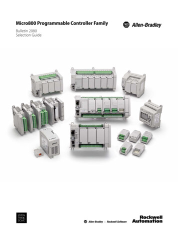
Chapter1Micro800 Plug-in ModulesPlug-in modules enhance the functionality of a base unit controller. With thesemodules, you can: Extend the functionality of embedded I/O without increasing thefootprint of your controller. Improve performance by adding additional processing power orcapabilities. Add additional communication functionality.Micro800 controllers support the following plug-in modules:Micro800 Plug-in , 12/24V DC Sink/Source input2080-IQ4OB4Digital8-point, Combo, 12/24V DC Sink/Source input12/24V DC Source output2080-IQ4OV4Digital8-point, Combo, 12/24V DC Sink/Source input12/24V DC Sink output2080-OB4Digital4-point, 12/24V DC Source output2080-OV4Digital4-point, 12/24V DC Sink output2080-OW4IDigital4-point, AC/DC Relay output2080-IF2Analog2-channel, Non-isolated unipolar voltage/currentanalog input2080-IF4Analog4-channel, Non-isolated unipolar voltage/currentanalog inputRockwell Automation Publication 2080-UM004D-EN-E - March 20181
Chapter 1Micro800 Plug-in ModulesMicro800 Plug-in l, Non-isolated unipolar voltage/currentanalog output2080-TC2Specialty2-channel, non-isolated thermocouple module2080-RTD2Specialty2-channel, non-isolated RTD module2080-MEMBAK-RTC(1)SpecialtyMemory backup and high accuracy RTC, 1 MB2080-MEMBAK-RTC2(1)SpecialtyMemory backup and high accuracy RTC, 4 MB2080-TRIMPOT6Specialty6-channel trimpot analog input2080-MOT-HSCSpecialtyHigh speed counter2080-DNET20Communication 20-node DeviceNet scanner2080-SERIALISOLCommunication RS232/485 isolated serial port(1) 2080-MEMBAK-RTC and 2080-MEMBAK-RTC2 are not supported on Micro820 controllers.2080-MEMBAK RTC is not supported on Micro870 controllers.Number of support for Micro800 plug-ins on the controllers are summarized inthe following table.Plug-in Slots on Micro800 ControllersControllerNumber of Plug-in SlotsMicro8100Micro8202Micro8302 (10/16 points)3 (24 points)5 (48 points)Micro8503 (24 points)5 (48 points)Micro8703ATTENTION: Removal and Insertion Under Power (RIUP) is not supportedon all Micro800 plug-in modules, except on the 2080-MEMBAK-RTC and2080-MEMBAK-RTC2 modules.ATTENTION: Micro800 plug-in modules can be installed on any plug-inslot on the controller, except for the 2080-MEMBAK-RTC and2080-MEMBAK-RTC2 modules which can only be installed on the leftmostplug-in slot.2Rockwell Automation Publication 2080-UM004D-EN-E - March 2018
Micro800 Plug-in ModulesDigital Plug-insChapter 112/24V Digital Plug-ins — 2080-IQ4, 2080-IQ4OB4, 2080-IQ4OV4,2080-OB4, 2080-OV4These digital plug-in modules provide transistor outputs for switching a varietyof 12/24V DC voltages to field loads and for detecting 12/24V signals from fielddevices.AC/DC Relay Output Module — 2080-OW4IThe 2080-OW4I is a 4-channel relay output and provides dry contact relayclosure outputs for switching a variety of AC and DC voltages to field loads.Analog Plug-insThe following analog plug-ins are supported by most Micro800 controllers.Non-isolated Unipolar Analog Input and Output — 2080-IF2,2080-IF4, 2080-OF2These plug-in modules add extra embedded non-isolated unipolar (0.10V,0.20 mA) analog I/O and offer 12-bit resolution.Specialty Plug-insNon-isolated Thermocouple and RTD — 2080-TC2 and 2080-RTD2These non-isolated plug-in modules help to make temperature control possiblewhen used with PID (Proportional Integral Derivative).See Non-isolated Thermocouple and RTD Plug-in Modules – 2080-TC2 and2080-RTD2 on page 19 for more information.Memory Backup and High Accuracy RTC — 2080-MEMBAK-RTCand 2080-MEMBAK-RTC2These plug-in modules allows you to make a backup copy of the project in yourcontroller, and adds precision real-time clock function without needing tocalibrate or update periodically.They can also be used to clone/update Micro800 application code. The2080-MEMBAK-RTC2 has larger memory to support clone/update forMicro870 application code. However, these plug-in modules cannot be used asadditional Run-Time Program or Data Storage for recipe and datalog.Rockwell Automation Publication 2080-UM004D-EN-E - March 20183
Chapter 1Micro800 Plug-in ModulesStatus IndicatorsStateDescriptionSolid red (2 s)Startup cycle test in progress.Flashing redBack up in progress.Solid red (continuous)Battery low.Project Backup and RestoreThe project can be backed up and restored using Connected ComponentsWorkbench software.Six-channel Trimpot — 2080-TRIMPOT6This trimpot plug-in offers an affordable method of adding six analog presets forspeed, position and temperature control.Channels45068012345High Speed Counter — 2080-MOT-HSCThis plug-in module provides enhanced high speed counter capabilities to theMicro800 controller. It supports the same functionalities of an embedded HSCon the Micro800 controllers but is enhanced to support up to 250 KHz 5Vdifferential line driver for improved noise immunity and provides additionaldedicated I/O.For more information, see High Speed Counter – 2080-MOT-HSC on page 25.Communication Plug-insRS232/RS485 Isolated Serial Port — 2080-SERIALISOLThe 2080-SERIALISOL plug-in supports CIP Serial (RS-232 only), ModbusRTU (RS232 and RS485), and ASCII (RS232 and RS485(1)) protocols. Unlikethe embedded Micro800 serial port, this port is electrically isolated, making itideal for connecting to noisy devices, such as variable frequency and servo drives,(1) RS-485 support is only available from Connected Components Workbench revision 6.4Rockwell Automation Publication 2080-UM004D-EN-E - March 2018
Micro800 Plug-in ModulesChapter 1as well as for communications over long cable lengths. Depending on theapplication and baud rate setting, you can extend this length.IMPORTANT2080-SERIALISOL is suitable for communication over longer cable lengthof up to 1000 m using RS485, with up to 19200 bps baud rate.The electrical characteristics of cable used and good wiring practices arevery critical in achieving reliable communication performance over longercable length. A shielded twisted pair RS485 22AWG cable (example:3106A from Belden) is recommended. Terminate both ends of the cablewith 120 ohm resistance.DeviceNet Scanner — 2080-DNET20The Micro800 DeviceNet plug-in module serves as a scanner and client forexplicit messaging to remote devices including I/O and drives, using a proven andwell-accepted fieldbus/network. It also provides better performance than usingserial and Ethernet (EtherNet/IP Class 3) communications.For more information, see the DeviceNet Plug-in – 2080-DNET20 on page 41.Rockwell Automation Publication 2080-UM004D-EN-E - March 20185
Chapter 1Micro800 Plug-in ModulesNotes:6Rockwell Automation Publication 2080-UM004D-EN-E - March 2018
Chapter2Install and Wire Your ModuleThis chapter provides hardware features, installation, and wiring connectiondiagrams for all the Micro800 plug-in modules.Hardware FeaturesThe plug-in modules, except for the 2080-MEMBAK-RTC and2080-MEMBAK-RTC2, can be plugged into any plug-in slots on theMicro800 controllers.Measurements in millimeters (inches)2080-RTD2 shownmounting untingscrew hole4501045811Side viewInsert Module intoControllerFront viewFollow the instructions to insert and secure the plug-in module to the controller.45012Rockwell Automation Publication 2080-UM004D-EN-E - March 20187
Chapter 2Install and Wire Your Module1. Position the plug-in module with the terminal block facing the front of thecontroller as shown.2. Snap the module into the module bay.3. Using a screwdriver, tighten the 10 12 mm (0.39 0.47 in.) M3 selftapping screw to torque specifications.See Specifications on page 61 for torque specifications.IMPORTANTWiringAnalog I/O performance depends on the application. For better noiseimmunity, cable length should ideally be less than 3 m because the plugins are non-isolated. For longer cable length requirements, use the 2085expansion I/O modules instead.The following plug-in modules have 12-pinfemale terminal blocks: 2080-IQ4,2080-IQ4OB4, 2080-IQ4OV42080-OB4, 2080-OV4, 2080-OW4I2080-IF2, 2080-IF42080-TC2, 2080-RTD2BackB123456A123456FrontTwelve-pin Female Terminal BlockPin Designations for 12-Pin Female Terminal Block 4,2080-OV4Not 2080-IQ4OB4,2080-IQ4OV4I-02COM3COMCOMCH0 CH0 I-03I-03Not usedO-3Not usedVI-2CH0-CH0-COMCOM-24V DCNot usedNot usedCI-2CJC CH0L (Sense)COM-24V DC-24V DCNot usedCOMCOMNot usedNot usedNot usedO-02O-02Not usedNot usedVI-3Not usedNot usedNot usedO-03O-03Not usedNot usedCI-3Not usedNot usedI-00I-00Not usedCOM0VI-0VI-0CH1 CH1 I-01I-01Not usedO-0CI-0CI-0CH1-CH1-COMCOM 24V DCCOM1COMCOMCJC-CH1L (Sense)COM 24V DC 24V DCO-1VI-1VI-1Not usedNot usedNot usedO-00O-00COM2CI-1CI-1Not usedNot usedNot usedO-01O-01O-2COMCOMTHNot usedRockwell Automation Publication 2080-UM004D-EN-E - March 2018
Install and Wire Your ModuleChapter 2Example Wiring for 2080-IQ4OB4 24V DC (Sinking)-24V DC (Sourcing) 24V DCCRCRDC inputB123456A123456SourcingoutputCRCR-24V DC (Sinking) 24V DC (Sourcing)-24V DCExample Wiring for 2080-IQ4OV4 24V DC (Sinking)-24V DC (Sourcing) 24V DCCRCRDC inputB123456A123456SinkingoutputCRCR-24V DC (Sinking) 24V DC (Sourcing)-24V DCExample Wiring for 2080-IF4Voltage transmitterShielded cableCurrent transmitterShielded cableB123456A123456Current transmitterShielded cableVoltage transmitterShielded cableRockwell Automation Publication 2080-UM004D-EN-E - March 20189
Chapter 2Install and Wire Your ModuleThe following plug-in modules have eight-pin female terminal blocks: 2080-OF2 2080-SERIALISOL 2080-MOT-HSCPin Designations for 8-Pin Female Terminal Block ModulesBackPinB1234A1234FrontA1A2A3Eight-pin female terminal (1) (2)COMRS485 B O-COMGNDA-COMRS232 RTSB-COMRS232 CTSZ-VO-0RS232 DCDO CO-0RS232 RXDA VO-1RS232 TXDB CO-1RS485 A-Z (1) IMPORTANT: Individually shielded, twisted-pair cable (or the type recommended by the encoder or sensormanufacturer) should be used for the 20
Purpose of this Manual This manual is a reference guide for Micro800 controllers, plug-in modules and accessories. It describes the procedures you use to install, wire, and troubleshoot your controller. This manual: explains how to install and wire your plug-ins gives you an overview of the Micro800 plug-in modules and accessories

