Transcription
WHOLE HOUSE WATER SOFTENING SYSTEMS1.0, 1.5, 2.0SERVICE MANUAL
TABLE OF CONTENTSSystem Information .3Application Limitations .4Maintenance Requirements .4Pre-Installation Instructions .4Installation Instructions .5-7Control Information .8Programming the Control .9-12Understanding the Diagnostic Level .13Start Up Instructions .14Sanitizing the Softener .14Exploded Views and Parts Lists .15-21Troubleshooting Guide .22-24Warranty Information .252
You now own the finest Water Treatment System available to homeowners. To enjoy the maximumbenefits of this system, please read the contents of this Owners Manual.SYSTEM INFORMATIONPOWER REQUIREMENTSThe computer board receives power from an external wall-mount transformer, supplied with eachsystem.Voltage: The voltage supplied to the computer board is 24V AC.Frequency: The line frequency is 50 Hz or 60 Hz.WATER PRESSUREA minimum of 20 pounds of water pressure is required for proper operation of the system. The statedoperating pressure range is 20 psi - 120 psi (138 kPa - 828 kPa).BYPASS VALVEThe bypass valve enables the customer to bypass the system in situations of: emergency leaks in theequipment, service calls and/or outdoor water use.TEMPERATURE OPERATING RANGESOperating Temperature Range: 40 F - 100 F (4.4 C - 38 C)Storage Range: The computer board can be stored at temperatures from -20 C (-4 F) to 70 C (158 F).Humidity: The computer board operates properly with relative humidity from 10% to 95%, noncondensing.ENVIRONMENTAL REQUIREMENTSLocation: The water softener and control cannot be exposed to outdoor elements, such as directsunlight or atmospheric precipitation. The system may be installed in a covered, open-air structuresuch as a carport, residential or commercial building. Weather covers are also available through theOrder Department ( part number 72370 ).OPERATIONAL SPECIFICATIONSUNIT SIZEMODELSERVICE FLOWRATE(GAL/MIN)PSI DROP ATSERVICE FLOWRATEDRAIN FLOWRATE(GAL/MIN)SALT PERREGENERATION (LBS)CAPACITY ATLOW SALTSETTING(GRAINS)CAPACITY ATCAPACITY ATMEDIUM SALTHIGH SALTSETTING(GRAINS) SETTING(GRAINS)EFFICIENCY(GRAINS/LB. OFSALT)1.0PENTAIR WATERSOFTENINGSYSTEM 1.011.6122.53.9 - 15.617500252003350044871.5PENTAIR WATERSOFTENINGSYSTEM 1.511.9152.55.2 - 23.424300370004860046372.0PENTAIR WATERSOFTENINGSYSTEM 2.013.2153.57.5 - 30.034600504006400046133
APPLICATION LIMITATIONS This system may be applied on municipality or well water systems. On hardness levels of 60 grainsand higher, the system may not achieve a hardness of less than 1 grain, due to high Total DissolvedSolids. (Some bleed through is possible.) Bleed through can also be caused by Sodium levels higherthan 1000 ppm. In either case, your system can be programmed to minimize these effects. See page8. When this system is installed on water with ferrous iron, also known as clear water iron, the maximumrange of reduction is based on local water conditions. The range is generally below 3 parts permillion. Your equipment may require special programming, along with an additive to the brine tank,to maximize the equipment’s ability to reduce iron. See page 8.MAINTENANCE REQUIREMENTSSALT RECOMMENDATIONSTwo kinds of salt are recommended for water conditioners:1. Block Salt: Water conditioner block salt is reasonably priced, low in impurities and will not cake inthe salt container. Block Salt is pressed into the shape of a cattle block.2. Solar Salt: Solar Salt is 98% pure salt, reasonably priced and low in impurities. Solar Salt is in theshape of pellets.THE REGENERATION VALVEThe regeneration valve is designed to last many years, but from time to time it may be necessary toclean and lubricate the moving parts. Your water quality and the amount of regenerations necessarywill affect this maintenance schedule.TESTING THE WATERThe water should be tested periodically (2 times a year minimum) with hardness test strips to ensurethat the system is performing accurately. Additional test strips can be purchased from the OrderDepartment. Test strip order number: 38306 pack of 50 test strips.PRE-INSTALLATION INSTRUCTIONS Do not install this system where water is microbiologically unsafe or of unknown quality withoutadequate disinfection before or after the system. This system must be installed in an area that is not affected by extreme heat, cold or the elements.The selected installation area must be adequate for easy service of all parts. This system must be installed in accordance with all applicable state and local laws and regulations. This system is designed to treat cold water only and can be installed on any cold water supply.4
INSTALLATION INSTRUCTIONS1. SAFETY PRECAUTIONS To prevent accident or injury, do not hoist the unit over your shoulder. Use a hand truck to transportthe unit. Note: Do not lay the unit on its side during transportation and/or installation. Wear safety glasses and work gloves during installation and service.2. TEST THE WATER HARDNESS The test strip provided is for testing the water hardness after the installation is complete to ensurethe system is functioning properly and for periodic testing. When programming the control it isnecessary to know the exact water hardness in grains per gallon. If you are using municipal water,your local water providers should be able to give you the hardness level. If you are using water froma private well, if may be necessary to have the water tested locally.3. CHECK WATER PRESSURE Use a pressure gauge to confirm that the water pressure does not exceed 120 psi. If the waterpressure does exceed this limit, install a pressure regulator on the inlet pipe of the unit. The minimumpressure for a conditioner is 20 psi. 60 psi is the optimum operating pressure.4. LOCATE A SITE FOR THE UNIT There are three primary requirements needed for a site: the main water source, a drain (the drain maybe a floor drain, a sewer trap, utility sink, vent stack, dry well, etc., depending on local plumbingcodes) and an electrical connection. Locate the system as close to these items as practical. Avoiddrain lines over 25 feet long. In most applications, bypass any outside faucets. Place the unit in the desired location. The location must have a level, smooth surface. If the system is located outdoors, protect the unit from direct sunlight. (Direct sunlight can damagethe fiberglass and other system components.) If necessary, build a box or shed. Note: The system canonly be installed outdoors in climates that do not reach freezing levels.5. TURN OFF THE WATER AND DRAIN THE PLUMBING Turn off the water at the meter or the pressure tank. Drain all the pipes. Do not sweat the pipes with water in them; steam will damage plastic parts in thevalve. To drain the plumbing system, open all the faucets in the house and flush the toilets. This procedurewill allow air to enter the plumbing system. The water will drain out of the lowest faucet or outlet.6. BYPASS THE OUTSIDE FAUCETS When possible it is best to bypass the outside faucets. However in some cases the outside faucetscan not be accessed. In this situation the bypass valve should be used whenever watering outsidefor extended periods of time. If the installation is outside or in a garage a faucet can be installed onthe inlet water side to provide an option for untreated water.7. CONNECT THE PLUMBING TO THE BYPASS VALVE AND BRINE TANK Do not point the soldering torch directly at the system. The thermo-plastic material will last a lifetime,within normal operating temperatures, but will melt in a torch flame.INLET To prevent hot water from backing up into the conditioner,avoid short connections of pipe between the conditionerand the hot water heater. If you can’t avoid a short connection, move the equipment to another location. As a last resort,install a check valve. If the check valve causes “waterhammer”, install a water hammer suppressor.OUTLET5
Connect the raw water pipe to the INLET pipe connection of the bypass valve. When looking at thefront of the unit, the inlet is the pipe connection on the LEFT side of the valve. Connect the treated water pipe to the OUTLET pipe connection of the bypass valve. When looking atthe front of the unit, the outlet is the pipe connection on the RIGHT side of the valve. Install the brine line to the brine tank.8. PLUMBING GROUND CONNECTION In some homes, metal piping may serve as a ground connection for the home electrical system.Installing a Pentair Softener with its nonmetallic valve body will interrupt the ground connection.Whenever a system is installed on metallic plumbing, we recommend you use grounding pipe clampsand a ground cable to maintain continuity of the ground connection from the inlet to the outlet pipe.¼” bare stranded wire is recommended for the ground cable. Check electrical continuity of theconnection after installation.9. INSTALL THE DRAIN LINE AND AIR GAP (AIR GAP NOT INCLUDED WITH THE UNIT) Using the supplied drain line fitting use Teflon tape on the threads and attach to the top of the valve.Run 1/2 inch I.D. flexible drain line tubing ( not supplied) to an appropriate drain. Most local codesrequire an air gap. See pictures below.Note: Drain line may be plumbed with rigid pipe or PEX, If required by local code. The drain connection onthe valve will accommodate any standard 3/4 inch NPT fitting. If you wish to use an air gap device (not included) you may purchase one from the Order Department.1/2 " DRAIN LINEGAP-A-FLOW AIR GAPFLOOR DRAINAir Gap Floor DrainPart Number: 131426DRAINSTACK"Mr. Drain"AIR GAPSTAND PIPEFORWASHER,Air Gap Mr. Drain,Part Number: 14199Standard Air Gap
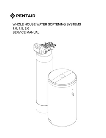
Special Attention for situations where a Filter and a Softener are installedtogether:When a whole house filter and a softener are installed side by side, the preferred approach is to run aseparate drain line from each unit all the way to the point of termination. If this is not done, there isthe potential for drain water from the filter to back feed through the softener and overfill the brinetank, especially when drain lines are run overhead. (Please note that back feed goes only into thebrine tank, not the service line.)If circumstances require you to tie the drain lines together, please use one of the following methodsto avoid back feed issues:Option 1: Run the drain lines from both systems to the point of termination, and tee them togetherbefore the air gap. (See figures below)TOLO APPCA ROTIO VENW DDITH RAIAIR NGAP2 SEPARATE DRAIN LINES2 SEPARATEDRAIN LINESTEEAIR GAPWATERINFILTERSOFTENERAPPROVED FLOOR DRAINTREATEDWATER OUTOption 2: Install a PVC check valve with a light spring on the Softener side to prevent back flow tothe Softener. (See figure below)TOLO APPCA ROTIO VENW DDITH RAIAIR NGAPSPRING CHECK ON DRAINLINE AFTER SOFTENERWATERINFILTERSOFTENERTREATEDWATER OUT7
CONTROL INFORMATIONPOWER ON LEDA green LED is ON when power is applied to the control and the microprocessor is operating properly.SERVICE REQUIREDIf the message “For Service Call” or “Service Required” displays in the window of the control withoutshowing the time of day, the control valve has encountered a problem, such as failure to reach theproper position during regeneration. The valve, the motor assembly, and board must be checked todiagnose and fix this problem.Note: It is normal for the message ‘For Service Call’ followed by a phone number to scroll acrossthe second line of the display. The time of day & capacity remaining will appear on line 1 duringnormal operation.TIME CLOCKThe time clock maintains the time of day for an extended period of time in the event of power loss. Asuper capacitor provides this function and eliminates the need of a battery. In the event the power is offpast the charge of the capacitor only the time of day is lost. The rest of the programming is stored inthe memory and will not need to be reprogrammed. When the power is restored the clock will restartat 8 AM and will need to be reset.REGENERATIONOnce an immediate regeneration is requested, a complete regeneration must occur to clear therequest. Once the regeneration starts, it must finish or the computer board will not clear. Manually walk(scroll) the control through regeneration to clear the computer board. If the regeneration is aborted andthe request is not cleared, another immediate regeneration will occur.HIGH-SPEED MOTOR OPERATION IN THE REGENERATION MODEHigh-sp
Turn off the water at the meter or the pressure tank. Drain all the pipes. Do not sweat the pipes with water in them; steam will damage plastic parts in the valve. To drain the plumbing system, open all the faucets in the house and flush the toilets. This procedure will allow air to enter the plumbing system. The water will drain out of the lowest faucet or outlet.