Transcription
Newport Medical Instruments, Inc.Newport e360 VentilatorOperating ManualFor Model e360S, e360P, e360EOPR360U Rev. H09-2014Newport Medical Instruments, Inc.1620 Sunflower Ave.Costa Mesa, CA 926260344email: venttechsupport@covidien.com
Contact InformationTelephone:800-255-6774 option #4 and option #2Hours:Monday through Friday, 8:00 am to 5:00 pm5-1OPR360U A0509Email:venttechsupport@covidien.comService Center Address:Covidien2824 Airwest Blvd.Plainfield, IN 46168Newport Medical Instruments1620 Sunflower AvenueCosta Mesa, CA 92626, USAEC REPAuthorized European RepresentativeEmergo EuropeMolenstraat 152513 BH, The HagueThe NetherlandsCopyright Information Copyright 2012 Newport Medical Instruments, Inc. All rightsreserved. The Newport e360 Ventilator system is manufactured inaccordance with Newport Medical Instruments, Inc. proprietaryinformation. The Newport e360 is covered under patent # 6,439,229.The information in this manual is the sole property of NewportMedical Instruments, Inc. and may not be duplicated withoutpermission. This manual may be revised or replaced by NewportMedical Instruments, Inc. at any time and without notice.5-1OPR360U Rev. HOPR360U A0509
FOLDOUT DRAWINGSUse these drawings for reference while reviewing the manual sections.34Alarms Screen High Paw Low Paw High MVE Low MVE High RR Apnea DisconnectThreshold2Main Screen Waves Loops Numerics Trends Freeze/SaveExtended Functions Insp Hold Exp Hold Event History Save FreezeSetup &Calibration Circuit Check Sensors Patient Setup Quick Setup* Technical Alarm History Alarm Loudness Alarm Tones Save5161Oxygen Inlet8VGA Connection2Air Inlet9USB Connection3Remote Alarm Connection10Cooling Fan4Alarm Speaker11Equipotential Ground StudExternal Alarm Silence12AC Power Connection13rd Party Humidifier4Support Arm with Rail Block52e360 Ventilator5Patient Breathing Circuit6On/Off Power Switch13Fuse Drawer3Optional 17” Display Monitor6Cart7RS232 Connection14External Battery ConnectionFigure F-1: Newport e360 Ventilator with AccessoriesAccessoriesFigure F-2: Newport e360 Rear PanelRear PanelPatient SetupPatient (Type)Ideal WeightVolume Units(mL, mL/lb/kg)SighCircuit TypeLeak Comp.Compl. Comp.Circuit Check(only in Ventilation Standby)Performs Leak, ComplianceFlow Sensor Calibration &Resistance TestSensorsFlow Sensor CalibrationO2 Sensor CalibrationQuick Setup*(only in Ventilation Standby)Establishes the startupventilation settingsTechnicalComm ProtocolDisplay BrightnessScreen FilesEvent History FilesDate FormatYear AdjustDay AdjustHour AdjustMinute AdjustRegional-Altitude-Language-Pressure Units*Not available on S modelFigure F-3: GUI Navigation MapNavigation MapOPR360U Rev. H
ADULTVTPC-SPONT05-01-2008 15:30IntBatHours999999.71Alarms Silence Button & Indicator2Alarm Reset Button3Graphical User Interface4360 Alarm Lamp5Alarms Screen Menu Button6GUI Screen Buttons Main Screen Menu Button Extended Functions Menu Button Setup & Calibration Menu Button7Pressure Bar Graph8Ventilation Controls9Adjustment Knob10Accept Button11Special Functions Non-Invasive Button Manual Inflation O2 (3 min) Button12Modes/Breaths Types Button13Power Indicators#3Graphical User InterfaceNOTE: The Circuit Check is only available in the Standby condition (only atpower on).Do not use a test lung to block the patient wye for the circuit check test.WARNING: Never connect the ventilator to the patient while in the Standbycondition.- Screen NavigationFigure F-4: Control Panel - English VersionControl PanelAGUI Status BarBMain Display AreaCData Sets BarDData Set Touch ButtonEGUI Menu Touch ButtonsFigure F-5: Circuit Check ScreenCircuit CheckOPR360U Rev. H
Table of Contents1 IntroductionDevice DescriptionIntended Use InformationAbout this ManualTyping ConventionsVersions and ConfigurationsService GuidelinesRegular ServiceComplete Service RecordsDisclaimersWarningsGeneral WarningsFilter WarningsPower Supply WarningsGas WarningsAuxiliary Equipment WarningsCautionsResponsibility for Patient SafetyLimitation of Liability5-1OPR360U A05092 Overview5-1Ventilator System OverviewControl Panel Layout and LabelingGraphical User Interface (GUI) and ControlsNavigation Map for GUI MenusLower Front Panel LayoutRear Panel LayoutNavigating the Control PanelUsing Touch-Turn-AcceptSelecting Mandatory Breath Type and ModeNon Invasive FunctionPatient Triggering MethodsBasic Ventilation ControlsFlow or Insp Time in Volume ControlManual Inflation ButtonO2 3 Minute ButtonAlarm Silence ButtonSuction Disconnect FunctionAlarm ResetGraphical User Interface (GUI) ScreensAlarms ScreenMain ScreenExtended Functions ScreenSetup & Calibration ScreenGUI Miscellaneous IndicatorsInternal BatteryOPR360U Rev. HOPR360U A0509
Table of Contents3 Unpacking, Assembly, and Safety Check5-1Unpack the VentilatorList of Package ContentsAssemblyExhalation Valve CompartmentConnect Air, Oxygen and AC PowerInstall the Breathing Circuit SystemSafety Check ProcedureSetup and InspectionEmergency Intake ValveCircuit CheckGas Supply AlarmsAC Power Loss/Battery Backup AlarmHigh/Low Airway Pressure Alarm/Circuit Disconnect Alarm/Alarm SilenceMinute Volume/Back Up Ventilation/Apnea AlarmsTrigger/Pressure SupportVolume/Flow/Rate Accuracy TestShut Down AlarmSafety Check Record SheetOPR360U A05094 Setting Up for Patient UsePower ConditionsShutdown AlarmOverview: Preparing for Patient VentilationSetup & Calibration MenuCircuit CheckOxygen and Flow SensorsExhalation Flow Sensor, CalibrationOxygen Sensor, CalibrationOxygen Sensor, DisablePatient SetupPatient CategoryWeight UnitsIdeal WeightVolume UnitsSighCircuit TypeLeak Comp (Leak Compensation)Compl Comp (Compliance Compensation)Quick Setup *Patient CategoryOPR360U A05095-1Ideal WeightWeight UnitsModeImplement Quick Setup*not available on S modelOPR360U Rev. H
Table of ContentsOPR360U A05095 Alarms5-1IntroductionVisual Alarm Displays360 Alarm LampAlarm and Message DisplayDevice Alert LEDGUI Alarm Screen EnvironmentAlarm Settings ScreenOPR360U A0509Saving the Alarm Settings ScreenAdjustable AlarmsAlarm HistorySaving the Alarm History Log*not available on S modelAlarm LoudnessOPR360U Rev. H5-1ExitTechnicalComm (Communications) ProtocolDisplay BrightnessRegional SettingsAltitudeLanguagePressure UnitsDate FormatDate and TimeScreen FilesEvent History FilesVentilator Controls GuideVentilator Settings in Advanced Data SetSlope/RiseExpiratory ThresholdPauseFlow WaveformVolume Target*Open Exhalation Valve*Inspiratory and Expiratory Hold ManeuversP0.1 Measurement FunctionNegative Inspiratory Force (NIF) ManeuverWaves and Loops DisplayAdjusting ScaleAuto ScaleUsing the Freeze FunctionEvent and Alarm History ScreenNumerics ScreenTrends ScreenData SetsSave FeatureDownload Feature
Table of ContentsAlarm TonesExiting Alarm ScreensFront Panel Alarm Interface EnvironmentAlarm Silence ButtonSuction Disconnect FeatureAlarm Reset ButtonNon-Adjustable AlarmsAlarm Violation and Remedy Guide5-1OPR360U A05096 Cleaning and MaintenanceIntroductionUse of FiltersInspiratory (To Patient) PortExpiratory (From Patient) PortDisassembly and Assembly ProceduresRear Panel Fan FilterExhalation ManifoldExhalation Flow Sensor and CableExhalation ValveInspiratory ManifoldFusesOxygen SensorCleaningSterilizingAutoclave SterilizationEtO SterilizationGuide to Cleaning and SterilizingGuide to Preventive MaintenanceStoring the VentilatorRepackaging the Ventilator7 Explanation of Modes, Breath Types andSpecial FunctionsIntroductionSettings FunctionsTiming Limitations to Ventilation ControlsControl RetentionControl RangeMandatory Breath TypesVolume ControlPressure ControlBiphasic Pressure Release Ventilation*OPR360U A05095-1Volume Targeted Pressure Control*Spontaneous Breath Management in SIMV and SPONTPressure SupportVolume Targeted Pressure Support*not available on S modelOPR360U Rev. H
Table of ContentsVentilation ModesA /CMVSIMVSPONT (Spontaneous)Advanced Features and Special FunctionsBias FlowSlope/RiseExpiratory Threshold and Flex CycleLeak CompensationCompliance CompensationNon-Invasive Ventilation-NIVLeak Compensation in NIVAlarms Settings in NIV5-1OPR360U A05098 SpecificationsAlarms, Controls, Monitored Data, Setup & CalibrationQuick Setup Table*Physical SpecificationsFoldout DiagramsFrontF-1 e360 Ventilator System and AccessoriesF-2 e360 Rear PanelF-3 Graphical User Interface (GUI) Navigation MapF-4 Control (Front) Panel - English VersionF-5 Circuit Check ScreenRearF-6 Main ScreenF-7 Extended Functions ScreenF-8 Alarms ScreenF-9 Quick Setup Screen*F-10 Technical ScreenF-11 Patient Setup ScreenF-12 Control (Front) Panel - Symbols VersionF-13 Order Information Optional Accessories5-1OPR360U A0509*not available on S modelOPR360U Rev. H
IntroductionIntroductionSection 1:
OPR360U A0509Device Description . 1-1Intended Use Information. 1-2About this Manual. 1-3Typing Conventions.1-4Versions and Configurations.1-4Service Guidelines . 1-5Regular Service . 1-5Complete Service Records . 1-5Disclaimers . 1-5Warnings. 1-5General Warnings.1-6Filter Warnings. 1-7Gas Warnings.1-8Auxiliary Equipment Warnings. 1-9Cautions. 1-9Responsibility for Patient Safety. 1-9Limitation of Liability. 1-105-1OPR360U A05095-1IntroductionSection 1:
1IntroductionDevice Description5-1The e360 Ventilator is a high performance microprocessor controlledventilator that is easy to use and maintain. The e360 features adual servo gas delivery system, a servo controlled active exhalationvalve, a simple to use interface and a touch screen graphics monitor.The electronically-controlled inlet gas mixing system is superiorto traditional pneumatic mixers that must exhaust gas from thesystem to consistently deliver precise oxygen concentrations.The dual servos respond immediately to changes in the set FIO2.Approximately 60 minutes of operational backup power is availablewhen the ventilator’s internal battery is fully charged. In addition,the e360 has remote alarm (nurse call) and external alarm silenceconnections, an RS232 interface to connect to central monitoringsystems, a VGA port to connect to an external monitor, and USB portfor uploading software and downloading saved files.OPR360U A0509When the e360 is turned on, the power on self-test (POST) verifiesthe integrity of the software and hardware of the ventilator. Duringoperation, the ventilator performs regular pressure transducercalibrations and software tests to ensure accuracy of monitored anddisplayed data. A user initiated Circuit Check ensures tests for leaksin the breathing circuit system, measures circuit compliance andresistance, and calibrates the exhalation flow sensor. User initiatedsensor calibration tests allow for calibration of the Oxygen andExhalation Flow Sensors.All breath types and modes include a range of ventilation and alarmsettings appropriate for adult or pediatric/infant patients. The e360has settable alarm limits for High and Low Peak Airway Pressure,High and Low Expiratory Minute Ventilation/ Back Up Ventilation,High Respiratory rate, disconnect threshold and Apnea. There arebuilt-in alarms for O2 monitoring, O2 and Flow Sensors, Low BaselinePressure, High Baseline Pressure, Sustained High Baseline Pressure,Ventilator settings violations, Low Battery, Gas Supply Failure, DeviceAlert, and Power Switchover.5-1The ventilator monitors and displays the power source, exhaledvolumes, peak flows, breath timing parameters (I:E ratio, respiratoryrate, and inspiratory time), delivered oxygen concentration, patientpressures (peak, plateau, mean airway, baseline) and pulmonarymechanics.OPR360U A0509During exhalation, the e360 uses a bias flow to flush exhaled CO2and stabilize temperature, humidity, and baseline pressure in thepatient breathing circuit. A stable baseline pressure between breathshelps to minimize auto-triggering.OPR360U Rev. H1-1
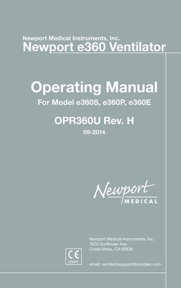
1 IntroductionThe heated exhalation system features an active exhalation valve witha low exhaled flow resistance for rapid return of circuit pressure tobaseline and decreased potential for auto-PEEP.5-1OPR360U A0509Figure 1-1 Newport e360 VentilatorIntended Use InformationThe e360 Ventilator System is intended to provide invasive ornoninvasive ventilatory support and monitoring for infant, pediatric,and adult patients with respiratory failure or respiratory insufficiency.The e360 Ventilator System is for use by prescription only. Onlythose who are professional healthcare providers with training in theuse of this ventilator system and experience with providing ventilatorsupport should use it.The e360 Ventilator System is for use in hospitals, healthcarefacilities, or during intra-hospital transport.Specific details about the intended use environment are available inSection 8 Specifications*.5-1OPR360U A0509*A critical care ventilator intended for use in transport within a professional healthcare facility isnot considered an emergency and transport ventilator.1-2OPR360U Rev. H
1IntroductionAbout this Manual5-1Foldout DrawingsFoldout pages containing frequently referenced diagrams are placedin the front and rear of this manual. These foldouts are designedfor easy reference while reading the manual and are designated asFoldout F-X. Foldouts F-1 to F-5 are located on the front foldoutpage and Foldouts F-6 to F-12 are located on the rear foldout page.OPR360U A0509Section 1- IntroductionThis section contains information about the safe use of the e360Ventilator system, information about this manual, general warningsand cautions.Section 2- Ventilator OverviewThis is the road map and directions for getting where you need togo. This section summarizes the elements of the ventilator system,controls, and functions.Section 3- Unpacking, Assembly and Safety CheckThis is the “putting it together/setting it up” section-use this as aguide to setting up the ventilator for the first time and performing asafety check. A sample record sheet is provided for documenting theresults of the safety check.Section 4- Setting Up for Patient UseThis is the “how to use” section. It will guide you through setting upthe ventilator for patient use and managing commonly used featuresduring ventilation.Section 5- AlarmsThis contains information related to the alarm systems and alarmtroubleshooting.Section 6- Cleaning and MaintenanceMake sure to follow these guidelines for cleaning, reprocessing,keeping the ventilator system in working order, storing, andpackaging for shipment.5-1Section 7- Explanation of Modes, Breath Types and SpecialFunctionsThis is the “how does it work” reference section of the manual togive you a general description of the e360 breath types, modes andOPR360U A0509special functions.Section 8- SpecificationsThis is where you will find ranges, physical dimensions, andinformation about settings, controls, alarms, and displays.OPR360U Rev. H1-3
1 IntroductionTyping Conventions5-1Controls, buttons, and alarms are shown in this manual as italicizedtext, written as they appear on the ventilator (for example, SPONT forspontaneous mode).OPR360U A0509WARNING! A Warning describes a condition that can cause personalinjury.Caution A Caution describes a condition that can cause damage toequipment.NOTE: A Note emphasizes information that is important or addsconvenience.Versions and ConfigurationsThis manual applies to software version 7.1 and later for the e360Ventilator System, which can be delivered in three configurations:e360S, e360P and e360E. Table 1-1 provides details about eachconfiguration.NOTE: This manual can also be used for model e360T, when the Tmodel addendum, “ADDOPR360T”, is included.Distinguishing Featuree360Se360Pe360EAutomatic Slope RiseNAYesYesFlex Cycle (Automatic Expiratory Threshold)NAYesYesVolume Target Pressure ControlNAYesYesOpen Exhalation Valve (for Biphasic Pressure NARelease Ventilation)YesYesExpanded tidal volume and resp. rate ranges YesNAYesTable 1-1 e360 Ventilator Model Configurations(NA not available)5-11-4AbbreviationLabeling on Control PanelWWEnglishOPR360U A0509OPR360U Rev. H
1IntroductionLabeling on Control bolsRURussian5-1AbbreviationOPR360U A0509Table 1-2 e360 Ventilator Control Panel Labeling ConfigurationsService GuidelinesRegular ServiceService must be provided at regular intervals by professionals whohave received training specific to the maintenance and repair of theNewport e360 Ventilator.Complete Service RecordsAll service performed on the e360 Ventilator System must berecorded in a service log in accordance with hospital procedures andlocal and national regulations.DisclaimersNewport Medical has no responsibility for the safe operation ofthe e360 Ventilator System if the intended use, intended user, andintended use environment requirements specified in this documentare not followed.Newport Medical has no responsibility for the safe operation of thee360 Ventilator System if operating instructions and maintenancespecified in this document are not followed or if service maintenanceor repairs are performed by persons who have not received theappropriate professional training.5-1Newport Medical disclaims all liability for the consequences ofproduct alterations or modifications, as well as for the consequencesthat might result from the combination of this ventilator with otherproducts, whether supplied by Newport Medical or by othermanufacturers, if such a combination is not endorsed by NewportMedical.OPR360U A0509WarningsFollow these safety guidelines. Additional warnings appear in contextthroughout this document.OPR360U Rev. H1-5
1 Introduction5-1General WarningsAll ventilator controls and alarm limits must be appropriate forthe patient’s condition, according to the therapy prescribed by aphysician.OPR360U A0509A patient connected to a ventilator requires the constant attentionof medical staff to the patient’s condition and to any significantdifference between monitored and set values that may indicate a faultin ventilator operation.Have an alternate method of ventilation available for use whenusing the e360 Ventilator. If the ventilator’s operation or monitoringfunctions are in doubt, discontinue ventilator use and employ analternate method of ventilation.Always use appropriate monitors to ensure sufficient oxygenationand ventilation (such as a pulse oximeter and capnograph) when thee360 Ventilator is in use on a patient.Have an alternate method of oxygen monitoring with high and lowalarms available for use when using the e360, in the event the built-inoxygen monitor is unavailable due to a disabled, defective or missingoxygen sensor.Always ensure that the caregiver can hear the audible alert whenthe alarm sounds. Do not use the ventilator in an environment whereaudible alarms cannot be heard by the caregivers.Before and during the use of the e360 Ventilator, make sure that allconnections in the patient circuit are secure. Ensure the integrity ofeach part of the patient circuit, humidifier connections and humidifierchamber.Always use clean breathing circuits.Dispose of waste products, residue, etc., in accordance with theappropriate regulatory requirements and facility policy.Follow your institutions infection control policy.Unqualified personnel must not attempt to service the ventilator5-1system. Improper repair or unauthorized modification can OPR360U A0509compromise safety and result in patient injury. The regularlyscheduled maintenance should only be done by a qualified servicetechnician using the e360 Ventilator Service Manual.1-6OPR360U Rev. H
1IntroductionFilter WarningsAt all times during patient use, keep clean, dry filters in the followinglocations to protect the patient and the ventilator:5-11. Between the Inspiratory (To Patient) Port and the inspiratory limbof the circuit2. Between the expiratory limb of the circuit and the Expiratory(From Patient) Port.OPR360U A0509If a clean, dry filter is not used on the Expiratory (From Patient) Port,sterilize the exhalation valve between every patient.If a clean, dry filter is not used on the Inspiratory (To Patient) Port,sterilize the inspiratory manifold should any of the following occurduring patient ventilation: Device Alert AlarmBoth Air/ O2 Supply Loss AlarmSustained High Baseline Pressure Alarm(These are alarms which cause the emergency intake/relief valve andexhalation valve to open.)Active humidification, nebulization or instillation of medications orliquids could result in moisture accumulation in the expiratory (FromPatient) filter. This could result in the following: Ineffective filtrationExpiratory volume monitoring inaccuraciesDamage to the Expiratory Flow SensorIncreased resistance to patient exhalationExhalation system obstructionTriggering difficultiesChange/discard dirty or wet filters in accordance with therecommendations of the filter manufacturer as well as the policy ofyour facility.Handle filters carefully to minimize the risk of infection as well asdamage to filters.Do not submerge filters in liquids of any kind.5-1A0509Between uses, reusable filters must be steam autoclaved OPR360Uand thenchecked for resistance, according to the manufacturer’s instructions.Power Supply WarningsTo maintain grounding integrity, connect the ventilator only to ahospital-grade receptacle.OPR360U Rev. H1-7
1 IntroductionAlways disconnect the ventilator from power before servicing.Do not use electrically conductive breathing circuit tubing.5-1Make sure the internal battery is fully charged to assure batteryoperation in case of AC power failure.OPR360U A0509To ensure that the internal battery remains functional, fully rechargethe battery at least every 2 months when the ventilator is not in use.This equipment has been tested and found to comply with the EMClimits for the Medical Device Directive 93/42/EEC(EN 55011 Class 1 and EN 60601-1-2). These limits are designedto provide reasonable protection against harmful interference in atypical medical installation. The equipment generates, uses, andcan radiate radio frequency energy and, if not installed and used inaccordance with these instructions, may cause harmful interferenceto other devices in the vicinity. However, there is no guarantee thatinterference will not occur in a particular installation. If this equipmentdoes cause harmful interference with other devices, which canbe determined by turning the equipment off and on, the user isencouraged to try to correct the interference by one or more of thefollowing measures: Reorient or relocate the receiving device.Increase the separation between the equipment.Connect the equipment into an outlet on a circuit different fromthat to which the other device(s) is connected.Consult the manufacturer or field service technician for help.Accessory equipment connected to the analog and digital interfacesmust be certified according to the respective IEC standards (e.g. IEC60950 for data processing equipment and IEC 60601 for medicalequipment). Furthermore, all configurations shall comply with thesystem standard IEC 60601-1-1. Any person who connects additionalequipment to the signal input or output parts “configures” a medicalsystem, and is therefore responsible for ensuring that the systemcomplies with the requirements of the system standardIEC 60601-1-1. If in doubt, consult the Technical Service departmentor your local representative.Gas Warningsof A05095-1Danger: There is a risk of explosion if used in the presence OPR360Uflammable anesthetics. The system is not intended for use withanesthetic gases.Use only dry clean, particle-free compressed air.1-8OPR360U Rev. H
1IntroductionOxygen source gas must be medical grade, 100% oxygen.Auxiliary Equipment WarningsNewport Medical cannot warrant or endorse the safe performanceof third party humidifiers for use with the e360 Ventilator. Contactthe manufacturers/distributors of third party humidifiers about thecompliance and performance characteristics of their products.5-1OPR360U A0509CautionsFollow these safety guidelines. Additional cautions appear in contextthroughout this document.Use only fuses with the correct rating.Do not immerse the ventilator in liquid sterilizing agents or liquids ofany kind.Do not spray cleaning solutions directly onto the front or rear panelsof the ventilator.Do not allow cleaning solutions to pool on the ventilator control panelor top of ventilator.Do not place liquids on or near the ventilator.Check with the manufacturer of all cleaning chemicals and sterilizingequipment to ensure safe handling procedures are followed.The Exhalation Flow Sensor is a precise and delicate instrument.Take care when handling not to disturb the measuring wires. Donot insert any object into the flow sensor, nor direct pressurizedflows of liquids or gases through the sensor during cleaning andreprocessing. The life cycle of the sensor is limited and will dependon observance of safe handling precautions and the ability tocalibrate the sensor. Always make sure that the flow sensor iscompletely dry before installation.Federal Law and Regulations in the United States and Canadarestrict this device to sale by or on the order of a physician.Responsibility for Patient Safety5-1A0509To use this product correctly and effectively and to avoid OPR360Uhazards,carefully read and observe all sections of this manual prior to use.Because the operating manual and labeling of the e360 VentilatorSystem assume that its sale and use are restricted to qualified,OPR360U Rev. H1-9
1 Introduction5-1trained professionals under the direction of a physician whounderstand the general operating characteristics of ventilators, thismanual includes instructions, warnings, and cautions that are specificto the design of this ventilator. This manual excludes references tohazards that are obvious to medical professionals, the consequencesof product misuse, or to potentially adverse effects in patients withabnormal conditions.OPR360U A0509Product modification or misuse can be dangerous. Newport Medicaldisclaims all liability for the consequences of product alterationsor modifications, as well as for the consequences that might resultfrom the combination of this ventilator with other products, whethersupplied by Newport Medical or by other manufacturers, if such acombination is not endorsed by Newport Medical.It is the responsibility of the ventilator operator to choose appropriatemonitoring of equipment performance and patient condition.Electronic surveillance of equipment performance and patientcondition cannot take the place of directly observing clinical signs.The ventilator operator is solely responsible for selecting the optimumlevel of patient monitoring.Limitation of LiabilityThe liability of Newport Medical, whether arising out of, or related tomanufacture and sale of the goods, their installation, demonstration,sales representation, use, performance, or otherwise, including anyliability based upon Newport Medical’s product warranty, is subjectto and limited to the exclusive terms and conditions as set forth,whether based upon breach of warranty or any other cause of actionwhatsoever, regardless of any fault attributable to Newport Medicaland regardless of the form of action (including, without limitation,breach of warranty, negligence, strict liability, or otherwise).The stated expressed warranties are in lieu of all other warranties,expressed or implied, including, without limitation, warranties ofmerchantability, fitness for any purpose, or non-infringement.Newport Medical shall not be liable for, nor shall the buyer be entitledto recover, any special incidental or consequential damages or anyliability incurred by buyer to any third party in any way arising out ofor relating to the goods.5-1OPR360U A05091-10OPR360U Rev. H
OverviewSection 2:Overview
OPR360U A0509Ventilator System Overview.2-1Control Panel Layout and Labeling.2-1Graphical User Interface Display (GUI) andControls.2-1Navigation Map for GUI Menus.2-1Lower Front Panel Layout.2-1Rear Panel Layout.2-2Navigating the Control Panel.2-2Using Touch - Turn - Accept.2-2Selecting Mandatory Breath Type & Mode. 2-3Non Invasive (Ventilation) (NIV) Function. 2-3Patient Triggering Methods. 2-4Basic Ventilation Controls. 2-4Flow or Inspiratory Time in Volume Control. 2-4Manual Inflation Button. 2-4O2 (3 min) Button. 2-5Alarm Silence Button. 2-5Suction Disconnect Function . 2-5Alarm Reset. 2-5Graphical User Interface (GUI) Screens . 2-5Alarms Screen . 2-5Main Screen. 2-6Extended Functions Screen.2-6OPR360U A05095-1Setup & Calibration Screen.
the integrity of the software and hardware of the ventilator. During operation, the ventilator performs regular pressure transducer calibrations and software tests to ensure accuracy of monitored and displayed data. A user initiated Circuit Check ensures tests for leaks in the breathing circuit system, measures circuit compliance and