Transcription
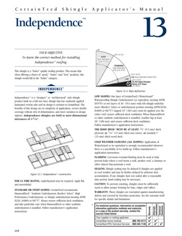
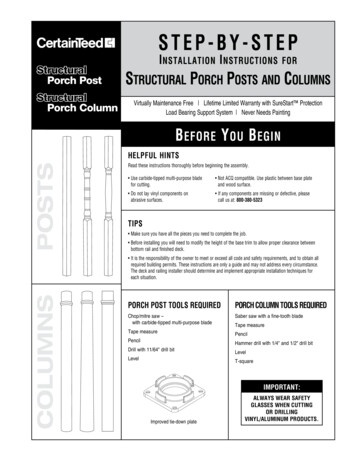
ST E P - B Y - ST E PSt ructuralPorch PostSt ructuralPorch ColumnI nstallation I nstructionsforStructural Porch Posts and ColumnsVirtually Maintenance Free Lifetime Limited Warranty with SureStart ProtectionLoad Bearing Support System Never Needs PaintingB efore Y ou B eginPostsHELPFUL HINTSRead these instructions thoroughly before beginning the assembly. Use carbide-tipped multi-purpose bladefor cutting. Not ACQ compatible. Use plastic between base plateand wood surface. Do not lay vinyl components onabrasive surfaces. If any components are missing or defective, pleasecall us at: 800-380-5323TIPS Make sure you have all the pieces you need to complete the job. Before installing you will need to modify the height of the base trim to allow proper clearance betweenbottom rail and finished deck.Columns It is the responsibility of the owner to meet or exceed all code and safety requirements, and to obtain allrequired building permits. These instructions are only a guide and may not address every circumstance.The deck and railing installer should determine and implement appropriate installation techniques foreach situation.Porch Post TOOLS REQUIREDPorch Column TOOLS REQUIREDChop/mitre saw –with carbide-tipped multi-purpose bladeSaber saw with a fine-tooth bladeTape measurePencilPencilHammer drill with 1/4" and 1/2" drill bitDrill with 11/64" drill bitLevelLevelT-squareTape measureIMPORTANT:Improved tie-down plateAlways wear safetyglasses when cuttingor drillingVINYL/Aluminum PRODUCTS.
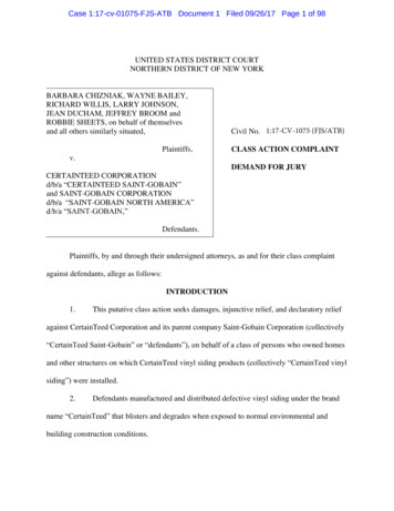
Installing Porch PostsFor 42" railing, do not cut any offbottom, just top of post.upper tie-down platelevel23For 36" railing, do not cut offmore than 6" from bottom, thencut balance off top.Step 1: M easure porch opening. Subtract3/4" from measurement toaccount for tie-down plates.Step 2: M easure and cut post to length.Note: For 42" railing, do not cutany off bottom, just top of post.For 36" railing, do not cut offmore than 6" from bottom, thencut balance off top.Step 3: I nsert top and bottom tie-downplates into ends of post.4lower tie-down plateStep 4: P osition post into place and plumb.Mark placement of tie-down plates.Step 5: T urn post a quarter turn clockwiseto expose tie-down attachmentscrew holes.Step 6: S ecure top and bottom tie-downplates to header and floor usingscrews provided.869Step 8: A t each end of the 4 sides of post,pre-drill attachment screw holes(11/64" bit) through post andreinforcement.Step 9: Secure post to top and bottom tiedown plates with screws provided.T ip: For concrete installation, Tapcon anchors are recommended (not provided).5Step 7: Turn post back into position.Step 10: I nstall trim pieces into placearound top and bottom of thepost to complete installation.tie-down plate1/8º turn4-piece trim10
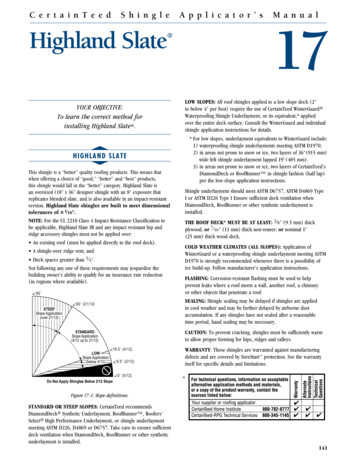
Installing Round Porch ColumnsCOLUMN TOPtop mounting platetop trimmid-trim ringextruded aluminum insertCOLUMNBOTTOMspacersbottom trimtapcon screwsbottom mounting plateNote: The Porch Column includescolumn, top mounting plate and bottommounting plate.Column Base/Cap Trim Kit includes toptrim, mid trim, bottom trim and hardware.For complete system, order both PorchColumn and Column Base/Cap Trim Kit.Note: If a railing system is beinginstalled with the lower rail at less than4-1/4" off of the deck, the base trim ringwill need to be cut to provide for thelower rail mounting bracket. Trim ringmust be cut before column is installed.Refer to Modifying Base Trim on thelast page.Step 1:Begin by laying out the placement ofthe columns. Typically, the center of thecarrying beam is determined along with thelocation of each column on that line. Markthe location on the center of each column.Using a “plumb bob,” determine the centerof the column at the floor level and markthat spot. With all column centers marked,snap a line the length of the project throughthe center marks.Step 2:Using the template that is provided withthe column trim, mark the center asestablished from the previous step. Alignthe centering marks of the template withthe project center line from the previousstep. Mark the position of the holes forthe bottom bracket and the trim locatorpins (bottom side of trim ring). Likewise,mark the position of the top bracketmounting holes (there are no locator pinson the top). Care in establishing the topand bottom bracket locations will enablethe column to be installed plumb. Thisis especially important when installingtapered columns.Step 3:Using a hammer drill, pre-drill 1/4" holesfor the bottom bracket at an angle thatwill be convenient to drive the screws intothe concrete when the Column assemblyis placed (see Step 11). Drill 1/2" holesfor the trim locator pins. These are drilledstraight into the concrete. Typically, it isnot necessary to pre-drill the top bracketholes. However, to ensure the mostcorrect placement of the bracket, you maywish to provide pilot holes.Step 4:If adjusting the length of the columnis required, slide the inner column andspacers out of the column from the base(straight) end. Measure and mark theamount to be removed and cut the innercolumn with a fine-tooth carbide blade ona chop saw.
Installing Round Porch Columns (cont)Step 11:Slide the assembly into position aligningthe brackets with the holes drilled inStep 2. Using a hammer drill, drive theTapcon screws into the concrete deck.Likewise, affix the top bracket to thecarrying timber.Step 5:Using a “T” square, mark the outercolumn (bottom straight end only).Step 8:Spacers need to be fixed in place using #8x2"self-drilling screws. Slide inner pipe withspacer into column. If a railing system is beinginstalled with the lower rail at less than 4-1/4"off of the deck, the base trim ring will need tobe cut to provide for the lower rail mountingbracket. Refer to Modifying Base Trim on thelast page.Step 12:In areas where uplift from high winds isconsidered a problem, pre-drill 15/64"holes through the column and bracket earsat the position of the bracket mountingtabs into the post approximately 1" fromthe bottom and 1" from the top.Step 6:Remove the unwanted amount using asaber saw with a fine-tooth blade.Step 9:Slide the mid-trim ring onto the column, asshown. 8" and 10" tapered columns have anoffset on which the ring rests. The locationof the rings for straight columns should bepre-determined (typically, 8" from the topon the 8" post) and marked.Step 13:Drive #14x4" screws into the column,securing the column to the bracket topand bottom. Placement of the top andbottom trim will hide the screws(2 screws per bracket).Step 7:Pre-assemble each column to be installedby first determining the position of theinner column spacers (34" for 36" highrailing, 36" for 42" high railing).Step 10:With the rings properly positioned on the8" straight column, drive #8x2" self-drillingscrews into the column through the holes inthe top of the ring, as shown. Slide the topand bottom trim over the column, followedby the top and bottom mounting brackets.Step 14:Top trim is now fixed to the carrying beamas shown using #8x2" self-drilling screws.
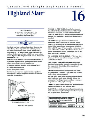
Installing Square Porch ColumnIf a railing system is being installed with thelower rail at less than 4-1/4" off of the deck,the base trim ring will need to be cut to providefor the lower rail mounting bracket. Trim ringmust be cut before column is installed. Referto Modifying Base Trim on the last page.Mark the location of the center of eachcolumn. Using a “plumb bob,” determinethe center of the column at the floor leveland mark that spot. With all column centersmarked, snap a line the length of the projectthrough the center marks.Step 1:Begin by laying out the placement ofthe columns. Typically, the center of thecarrying beam is determined along withthe location of each column on that line.Step 2:Using a hammer drill, pre-drill 1/4" holesfor the bottom bracket at an angle thatwill be convenient to drive the screws intothe concrete when the column assemblyis placed. Typically, it is not necessary topre-drill the top bracket holes. However,to ensure the most correct placement ofthe bracket, you may wish to provide pilotholes.Step 3:Using a “T” square, mark the outer column.Step 4:Remove the unwanted amount using a sabersaw with a fine-tooth blade.Step 5:Slide the mid-trim ring onto the column.Step 6:With the ring properly positioned on thecolumn, drive #8x2" self-drilling screwsinto the column through the holes in thetop of the ring. Slide the top and bottomtrim over the column, followed by thetop and bottom mounting brackets. If arailing system is being installed with thelower rail at less than 4-1/4" off of thedeck, the base trim ring will need to becut to provide for the lower rail mountingbracket. Refer to Modifying Base Trimon the last page.Step 7:Slide the assembly into position aligningthe brackets with the holes drilled inStep 2. Using a hammer drill, drive theTapcon screws into the concrete deck.Likewise, affix the top bracket to thecarrying timber.Step 8:In areas where uplift from high winds isconsidered a problem, pre-drill 1/4" holesthrough the column and bracket ears atthe position of the bracket mounting tabsinto the post, approximately 1" from thebottom and 1" from the top.Step 9:Drive #14x4" screws into the column,securing the column to the bracket topand bottom. Placement of the top andbottom trim will hide the screws (2screws per bracket).Step 10:Top trim is now fixed to the carryingbeam using #8x2" self-drilling screws.
Modifying Base Trim for Porch ColumnsWhen Installing Railing SystemStep 1:Determine the height and placement ofthe bottom rail. You can use the bottomrail from the system you are installing tohelp. Be sure to check local codes for themaximum distance from the deck surfaceto the bottom of the railing.Step 2:Mark the location where the rail will fallon the base trim. Include railing trim coverwhen marking for cutout.Step 3:Cut out base trim where you marked.Step 4:Continue with column installation.Step 5:Follow the railing system instructions forthe system you are using to complete therailing installation.ASK ABOUT OUR OTHER CERTAINTEED PRODUCTS AND SYSTEMS:E x terior : R o o f i n g S i d i n g W i n d o ws F e n c e R a i l i n g T R I M D e c k i n g F o u n d a t i o n s P I P EI nterior : I n s u l a t i o n G Y P S U M C e i l i n g SCertainTeed CorporationP.O. Box 860Valley Forge, PA 19482Professional: 800-233-8990Consumer: 800-782-8777www.certainteed.comCode No. 40-70-825, 9/10 CertainTeed Corporation, Printed in U.S.A.
Continue with column installation. step 5: Follow the railing system instructions for the system you are using to complete the railing installation. CertainTeed Corporation P.O. Box 860 Valley Forge, PA 19482 Professional: 800-233-8990 Consumer: 800-782-8777 www.certainteed.com ASK ABOUT OUR OTHER CERTAINTEED PRODUCTS AND SYSTEMS: