Transcription
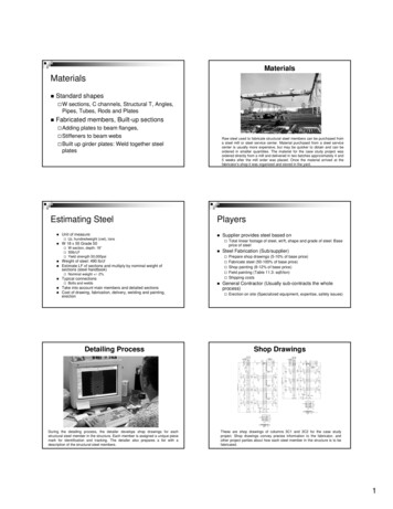
MaterialsMaterials Standard shapesW sections, C channels, Structural T, Angles,Pipes, Tubes, Rods and Plates Fabricated members, Built-up sectionsAdding plates to beam flanges,Stiffeners to beam websBuilt up girder plates: Weld together steelplatesEstimating Steel Unit of measure: W 18 x 55 Grade 50Raw steel used to fabricate structural steel members can be purchased froma steel mill or steel service center. Material purchased from a steel servicecenter is usually more expensive, but may be quicker to obtain and can beordered in smaller quantities. The material for the case study project wasordered directly from a mill and delivered in two batches approximately 4 and5 weeks after the mill order was placed. Once the material arrived at thefabricator’s shop it was organized and stored in the yard.Players Lb, hundredweight (cwt), tonsW section, depth: 18”55lb/LFYield strength 50,000psi Weight of steel: 490 lb/cfEstimate LF of sections and multiply by nominal weight ofsections (steel handbook) Typical connections Take into account main members and detailed sectionsCost of drawing, fabrication, delivery, welding and painting,erection Total linear footage of steel, wt/ft, shape and grade of steel: Baseprice of steel Detailing ProcessDuring the detailing process, the detailer develops shop drawings for eachstructural steel member in the structure. Each member is assigned a unique piecemark for identification and tracking. The detailer also prepares a list with adescription of the structural steel members.Steel Fabrication (Sub/supplier)Prepare shop drawings (5-10% of base price)Fabricate steel (50-100% of base price)Shop painting (8-12% of base price)Field painting (Table 11.3: sqft/ton)Shipping costsNominal weight /- 2%Bolts and weldsSupplier provides steel based on General Contractor (Usually sub-contracts the wholeprocess)Erection on site (Specialized equipment, expertise, safety issues)Shop DrawingsThese are shop drawings of columns 3C1 and 3C2 for the case studyproject. Shop drawings convey precise information to the fabricator, andother project parties about how each steel member in the structure is to befabricated.1
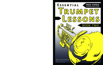
Anchor Rod PlanAnchor Rod DetailsOne of the first drawings prepared by the detailer is the anchor rod plan.This plan guides the foundation subcontractor in the placement of anchorrods. It contains horizontal and vertical information for placement ofanchor rods, as well as dimensions and elevations of leveling plates (ifused).The anchor rod detail on the left depicts how anchor rods and leveling plates wereplaced for the case study project. A leveling plate is a steel plate fixed on top of afoundation on which a structural column can be placed. The leveling plate isleveled and grouted prior to installation of the column. Although this is one methodfor setting columns, practices may vary with other erectors. On the right is aphotograph of the anchor rods and leveling plates in place for the case studyproject.FabricationPiece MarkStructural steel members are fabricated by precisely cutting, shearing,punching, drilling, fitting and welding in order to produce theconfigurations detailed in the shop drawings. Each member is labeledwith a piece mark, length, and job number for identification.TransportationOnce the on-site crane was fully set up, the fabricator loaded the steelmembers for sequence 1 onto trucks and transported them to the job site.Structural steel was delivered by sequence throughout the erection process. Ittook a total of 29 truckloads to deliver all of the structural steel for the project.Once fabricated, each finished structural steel member is labeled. In this casethe fabricator labeled each steel member with its piece mark, sequencenumber, and the last two digits of the job number. Specific labeling practicesmay vary by fabricator. Notice that this time the label color is yellow todifferentiate it from previous labels. Labeling of the steel pieces is crucialbecause it will help identify members on the job site.Unloading and ShakeoutUpon delivery to the job site, fabricatedsteel was unloaded and placed on wood orsteel blocking. The blocking allowed forchokers to be attached to each member forsubsequent hoisting and erection. Shakeoutof structural steel took place afterunloading. Shakeout is the process ofsorting the steel pieces on the site so thatthey can be efficiently erected (lower left),and involves organizing and spacing eachstructural steel piece.2
StorageAfter fabrication, finished structural steel members are stored in thefabricator’s storage yard. The more organized the yard, the easier it will beto transport steel to the site. In this case structural steel was storedaccording to erection sequence. Sequences define areas of the frame andare used to organize their delivery and erection. The practice of planningand storing by sequence improves the efficiency of loading, delivery,offloading and erection.Structural Steel Construction PhaseScheduleAs seen on the schedule, material procurement occurs early in the process, evenbefore shop drawings are generated. This is done so that a steel mill has enoughtime to produce the required steel. Material procurement includes: quantitysurveying, placing the mill order, delivery of steel from the mill and storage of thesteel in the fabrication shop. Detailing includes the creation of shop drawings ofeach piece in the structural frame. Shop drawings are submitted to the contractorand structural engineer to ensure that they comply with the engineer’s design.Upon approval of shop drawings and arrival of steel from the mill, steel pieces areprecisely fabricated. Once structural steel members are fabricated they are takento the yard, loaded on trucks and transported to the job site for erection.Case Study ProjectDescription of the structural steel frame: Office building use 4 Stories 80,000 square feet of buildingconstruction area Approximately 400 tons of structuralsteel or 10 pounds per square foot Approximate fabrication and erectioncost 9 dollars per square foot Standard bay size of 30ft by 30ft 3 by 7 bays 964 pieces of structural steel Built in 2003Hoisting SequencesDuring detailing, the steel frame was divided into 6 sequences illustrated on theerection drawings. Sequences represent the order in which a zone or section of theframe will be erected. They are designed to improve efficiency of the erectionprocess. Planning the sequences allowed for parallel construction operations to takeplace. For example, while the erection crew erected sequence 2, the decking crewplaced metal deck at the previously placed sequence 1. In this way the deck placedat sequence 1 formed a work platform and reduced the potential fall distance whenthe steel contractor erected sequence 3 which was above sequence 1.Structural Steel Erection ScheduleSafety Concerns All employees must be have fall protection at 15 feet, except fordeckers in controlled decking zones and connectors [§.760(a)]Controlled decking zone (CDZ) means an area in which certainwork (for example, initial installation and placement of metaldecking) may take place without the use of guardrail systems,personal fall arrest systems, fall restraint systems, or safety netsystems and where access to the zone is controlled.Controlling contractor to provide erector with a safe site layout.Minimizes employee exposure to overhead loads through preplanning and work practice requirements.This is a detailed schedule of the erection process of the structural steel frame. In thisproject an average of 40 pieces of steel were hoisted per day. Hoisting, bolt up, detailwork, decking and stud activities are performed by sequence. Hoisting consists oflifting and placing steel members into their appropriate position and temporarilyfastening them using several bolts and/or welds. Plumbing up refers to the verticalalignment of the frame. Final bolt up refers to tightening the bolts which connect thecomponents of the structure.3
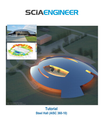
STRUCTURAL STEEL ERECTION BYSEQUENCEThe following is an animation of the structural steel erection process bysequence. The six sequences will slowly appear along with the working day inwhich hoisting of each sequence was completed. The last images to appearare of the masonry stair and elevator shafts. They were built after the framewas erected. The steel frame was connected to the vertical shafts to providepermanent lateral stability of the frame.Erection OrderThe erection crew foreman used the erection drawings to determine the exactorder in which structural steel members were to be erected. The first pieceshoisted during this project were the columns in sequence 1 (right sheet), thengirders and beams (left and center sheets).Erection CrewSeven people formed the erection crew used for this project. The crewconsisted of one foreman, two ironworkers hooking steel (upper left), twoironworkers connecting steel (upper right), a crane operator (lower left), andan oiler (lower right).Erection DrawingsThis is the erection drawing (e-drawing or e-sheet) of the first floor framing for theproject. The numbers one and two inside the red hexagons on each side of the redline indicate the sequence number for each part of the structure. The piece markson the drawing match those on the beams, girders and columns and are used tolocate and orient each member during erection.ChokersA choker is a rigging assembly used to attach a load to a hoisting device. Itis usually made of wire rope or synthetic fiber. Chokers are used to hoistbeams into position. They are positioned at the center of gravity of thebeam so that the beam remains level when hoisted.4
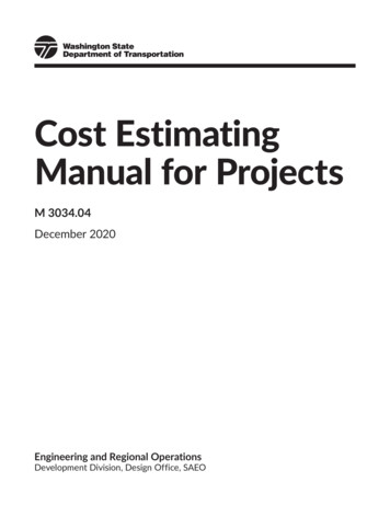
Multiple Lift RiggingMultiple lift rigging is a process used to hoist several pieces of steelsimultaneously. This is accomplished by utilizing a rigging assembly thatfacilitates the attachment of up to five independent loads to the hoistrigging of a crane. In this project up to four beams were hoisted at a time.Multiple lift rigging speeds the lifting process by reducing the total numberof lifts required for the frame.Sequence 1 ColumnsThe first structural steel members hoisted were the columns. This is aview of sequence 1 after the columns were set. Notice that all columnshave a splice on the top.Metal DeckingThis is the metal decking used in the project. The erector had theresponsibility of unloading and hoisting metal decking to preestablished positions on the frame.Preliminary BoltingThe connector uses pins to align the holes between structural steel membersbeing connected. Then he places several bolts and temporarily tightens themwith his spud wrench. At least two bolts per connection are used totemporarily fasten each connection.BeamsMain girders are hoisted after the columns. Beams are then hoistedand connected to the girders. On the left is a photograph of the firstbay to be hoisted. On the right is a photograph of the first three baysin place.Hoisting Metal DeckingOn the left is a plan specifying wherebundles of decking were to be placed bytheerector.Considerationsforplacement locations included both theproductivity of the deck installers andconstruction loading. Each bundle wasidentified with a number and placed atits preplanned location.5
Metal DeckingMetal deck was placed and attached with a series of welds. Controlled deck zoneswere used during installation. A controlled deck zone is an area in which initialinstallation and placement of metal decking may take place without the use ofguardrail systems, personal fall arrest systems, fall restraint systems, or safety netsystems and where access to the zone is controlled.Perimeter Safety CablesOn multi-story structures, perimeter safetycables are installed at the interior and exteriorperimeters of floors and openings as soon asthe metal decking has been installed.Shear StudsThis is a view of the welded studs. Shear studs were tested to ensure that theywere correctly welded to the structural steel members in compliance with the bendtest of the AWS D 1.1 Structural Welding Code.Shear StudsThese are shear studs. The white rings are ceramic ferrules. The ceramicferrule constrains the molten metal into which the stud is thrust automaticallyand a high quality fusion weld is accomplished where the weld is strongerthan the stud itself.Welding Shear StudsSnow was removed from the locations where shearstuds were to be placed (upper left). Using a studwelding gun (an automatic welding device) the shearstuds were then welded to the structural membersbelow the metal decking. Shear studs are used toensure a composite action between the concrete slaband structural steel beams (upper right). Whether shearstuds are used is a function of the structural engineer’sdesign.Sequence 1Sequence 2This is a view of the completed hoisting activity for sequences 1 (left)and 2 (right). It took approximately 5 days to hoist the 166 pieces ofsteel that are part of the two sequences.6
Sequence 3Sequence 4This is a view of the completed hoisting activity for sequences 3 and 4.Hoisting these two sequences took approximately 9 days in contrastwith the five days it took to hoist sequences 1 and 2, becausesequences 3 and 4 consisted of two floors (365 pieces of steel) andsequences 1 and 2 consisted of one floor (166 pieces of steel).Erection ScheduleThe activities in yellow are the ones completed by the time sequence 4 was hoisted.Notice that deck and studs for sequence 3 were started before hoisting sequence 5 inorder to provide fall protection for the ironworkers connecting steel. Plumbing up andfinal bolt up for sequences 1 through 4 were performed after sequence 4 was hoisted.Plumbing UpPlumbing up refers to the vertical alignment of the structure. Atheodolite was used to verify the alignment of columns in theperimeter of the building. The foreman directed ironworkers on thestructure to shift the frame using the temporary bracing.Erection ScheduleThe activities in yellow were completed by the time sequence 2 was hoisted.No
Cost of drawing, fabrication, delivery, . placed metal deck at the previously placed sequence 1. In this way the deck placed at sequence 1 formed a work platform and reduced the potential fall distance when the steel contractor erected sequence 3 which was above sequence 1. Safety Concerns All employees must be have fall protection at 15 feet, except for deckers in controlled decking .