Transcription
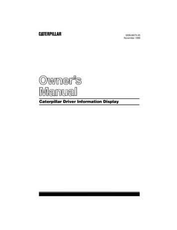
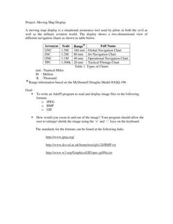
Project: Moving Map DisplayA moving map display is a situational awareness tool used by pilots in both the civil aswell as the military aviation world. The display shows a two-dimensional view ofdifferent navigation charts as shown in table ll NameRangeΨ160 nmi Global Navigation Chart80 nmi Jet Navigation Chart40 nmi Operational Navigation Chart20 nmi Tactical Pilotage ChartTable 1. Types of Chartsnmi : Nautical MilesM : MillionK : ThousandΨRange information based on the McDonnell Douglas Model #ASQ-196Goal:To write an Ada95 program to read and display image files in the followingformatso JPEGo BMPo GIFHow would you zoom in and out of the image? Your program should allow theuser to enlarge/ shrink the image using the ‘ ’ and ‘–’ keys on the keyboard.The standards for the formats can be found at the following IF/spec-gif89a.txt
Figure 1. SM-4000 COLOR Skymap IIIC by Bendix/King** Source : http://www.avionix.com/movmap.htmlGiven that your moving map display size is 4.5” x 4.5”:Issues to take into consideration areAircraft speed varies from 0 – 480 knots.Turns are constant at 7 degrees per second.Time taken to switch between the maps.Time taken to enlarge/ shrink the maps.Which of the format (GIF/ JPEG/ BMP) would you choose for your moving mapdisplay? Justify your answer.
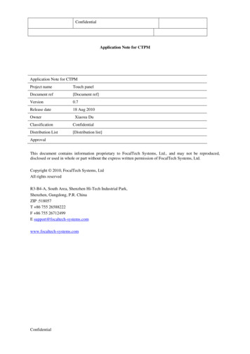
Project: Attitude and Direction IndicatorThe Attitude Direction Indicator shows the roll and pitch of the A/C. The upper half ofthe display is blue (sky) the lower half is brown (terrain). The borderline between thehalves is the horizon. The horizontal bar represents the A/C in relation to the horizon.The white bars (one horizontal, the other one vertical) are the indicators when in ILSmodus, showing the aircraft's position in relation to the glide-slope and inbound vector ofthe runway. If the A/C outside the max. ranges of GS and Course, the bars are locked onone side of the indicator.Goal:Write an Ada95 program to create the display shown below (Attitude andDirection Indicator). Use the AdaOpenGL binding to create the graphics.Figure 1. Attitude and Direction Indicator** Source: http://xflight.powerweb.de/original/parts/center console/adi/adi 01.jpgThe openGL package can be found athttp://adaopengl.sourceforge.net/The user should be able to control pitch and roll from the keyboard. You mayassign the keys ahead of time and display it when the program starts.Issues to be considered are:What is the maximum pitch rate/ roll rate of the aircraft?How long does it take to update the display once the user enters a command?Write a two page memo to the designers of the JSF based on your project,explaining what you think the key design issues in designing the display are.
The specification of the frame of reference is one of the most significant design questionsfor spatial displays, since it determines from where the situation is depicted and whichvariables are presented as dominant cues.Inside-out refers to a presentation of the world related information as it would beobserved from within the aircraft. Outside-in refers to a viewpoint which is stabilized in aworld-referenced system. Stokes et al. (1990) present three principles that shouldinfluence the choice: The principle of the moving part. Constancy of reference frames. The principle of frequency separation.The principle of the moving part assumes that people have certain expectations aboutwhat actually moves in a system. The element that moves on the display should be thesame and move in the same direction as the operator's expectation of motion. Theprinciple of constancy of reference frames is based on the fact that humans have adifficult time rapidly reorienting between different frames of reference. When aninstrument represents an abstraction of the real world and the user is required to switchbetween the instrument and the real world, different frames of reference can result incontrol blunders. This is caused by the fact that to compensate for a given displaymovement, the required direction of the control action may be opposite between the twoframes of reference.In case of an artificial presentation of the outside world, the principle of the constancy ofreference frames leads to the conclusion that, to maintain static compatibility with theoutside worldview, an inside-out frame of reference should be used. However, theprinciple of the moving part suggests, that to maintain dynamic compatibility, themovement of the display should be consistent with the pilot's mental representation thatthe aircraft moves, and hence an outside-in frame of reference is required (Johnson andRoscoe, 1972). The attitude direction indicator (ADI) presents the pitch and bank of theaircraft relative to a depiction of the horizon. In general a so-called inside-out frame ofreference is used (fixed airplane symbol against a moving horizon).With an outside-in frame-of reference, the horizon is fixed and the aircraft rolls right andleft and pitches up and down. To prevent the aircraft symbol from going off the scale, thecomplete pitch range must be visible, posing quite a design challenge since the combinedrange and resolution requirements can result in a rather large display.Russian aircraft employ a hybrid solution, in which the aircraft symbol rolls but is fixedin the vertical direction, and the artificial horizon translates in the vertical direction toconvey pitch information. By allowing the aircraft symbol to roll against a fixedbackground, the principle of control display motion compatibility is satisfied. Whenregarding an attitude indicator as a display of which the error must be zeroed, control
reversals can results. Therefore, an inside-out frame of reference must convey the illusionthat the aircraft is moving.
Project: Data LinksData links allow aircraft to transmit information in real- or near real-time. A studyreleased by Forecast International, Newtown, Conn., said that the U.S. airbornecommunications market will be worth some 2.63 billion over the next decade. There aretwo key communication links (besides the traditional data buses such as MIL-STD-1553,ARINC 429 and ARINC 629) are RS232 and TCP/IP.RS232 has been around for a very long time and is typically used to connect thefire control computer on-board the aircraft to the weapon delivery sub-systems(fuzing and release).TCP/IP, which has been the driving force behind the internet, and is now beingexplored for Aircraft use.Goal:Write an Ada95 program that will enable RS232 communication between twocomputers.Write an Ada95 program to allow two computers on the internet to communicatewith each other. Use Ada Sockets to establish the connection between themachines.Boeing/ Honeywell have been considering using TCP/IP in commercial aircraft.Write a two page memo detailing the advantages/ disadvantages of both serialcommunication and TCP/IP.The RS-232 standard can be found mThe AdaSockets package/ usage is present athttp://www.rfc1149.net/devel/adasockets
Project: Fuel ManagementFull Authority Digital Engine Control (FADEC) is an engine manage that monitors fuelconsumption and optimizes engine performance. The FADEC has to take intoconsideration the flight envelope of the aircraft, the mode of operation and inform thepilot when bingo fuel is reached.Goal:Write a FADEC using Ada95 for a combat aircraft of your choice. Your softwaremust take into considerationo Flight envelope of your aircrafto Engine performance over the entire flight envelopeCruiseMach holdAltitude HoldAfter-burnerso It should inform the pilot when bingo fuel is reached.o It should handle air-air refueling operations and inform the pilot when tobreak away from the tankerThe USAF has recently selected the x-35 to be the JSF. Write a two-page memodetailing what they should be looking for in the fuel management system.Issues to consider includeo How do you model the aircraft?o How do you model engine fuel consumption?o How do you model fuel flow from tanker to fighter?o How do you simulate the operation of the aircraft?
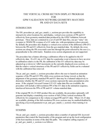
Project : Kalman Filtering for Position and Velocity EstimationIn 1960, R.E. Kalman published his famous paper describing a recursive solution to thediscrete-data linear filtering problem. Since that time, due in large part to advances indigital computing, the Kalman filter has been the subject of extensive research andapplication, particularly in the area of autonomous or assisted navigation.The Kalman filter is a set of mathematical equations that provides an efficientcomputational (recursive) solution of the least-squares method. The filter is verypowerful in several aspects: it supports estimations of past, present, and even futurestates, and it can do so even when the precise nature of the modeled system is unknown.The US Navy has been working on the Small Autonomous Underwater Vehicle to act asa countermeasure for shallow underwater mines. One of the key components is tointegrate the Inertial Navigation System and the Global Positioning System to improvenavigational accuracy.Figure 1. Block Diagram of the Kalman Filter
Goal:To write an Ada95 program that implements a kalman filter for integrating GPSand INS information.Based on your experience in this project, write a memo for the US NAVY, citingthe advantages and disadvantages of using a kalman filter for integrating sensorinformation.A block diagram of the Kalman filter to be implemented is shown in figure 1.A link to a tutorial on Kalman Filtering is given belowhttp://www.cs.unc.edu/ welch/kalman/kalmanIntro.html
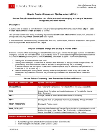
Project : Missile Target Simulation using Proportional NavigationProportional navigation is the guidance law used by most missiles in operational usetoday. This method of guidance, generates missile acceleration commands in proportionto the line-of-sight (LOS) rate. The missile-target geometry is shown in figure 1 below.Figure 1: Missile Target GeometryWhere:Vt : Target VelocityVm : Missile Velocityγt : Target Flight Path Angleγm : Missile Flight Path AngleR : missile range to targetRt : Target RangeRm : Missile rangeσt : Target Line of Sightσm : Missile Line of Sight
The proportional navigation scheme is illustrated in figure 2. Assuming that the missileseeker head follows the aircraft, the transverse acceleration perpendicular to the line ofsight will be equal to the acceleration of the R vector in that direction.Figure 2. Vectorial Proportional NavigationGoal:Write an Ada95 program to simulate a simple missile engagement scenario.Assume that the target travels at a constant velocity.The US ARMY is trying to decide which missiles to buy for a Surface-to-Airshort range missile. Based on your experience in this project, write a two-pagememo explaining which guidance algorithm you would choose and why.Read Tactical and Strategic Missile Guidance by Paul Zachran. You will find a lot ofcode written in fortran which can easily be converted into Ada95.
Project: MIL-STD-1553The MIL-STD-1553 is a military standard that defines the electrical and protocolcharacteristics for a data bus. The standard was released in 1973 with the primary userbeing the Air Force’s F-16. Since that time, it has undergone two revisions, Notice 1,released in 1980 and the tri-service Notice 2 in 1986. The Notice 2 to the standardremoved all references to ‘aircraft’ or ‘airborne’ so as not to limit usage of the bus.Outside of the military domain, it has been successfully applied to e.g., the BART (BayArea Rapid Transit) subway system and manufacturing production lines. We use 1553 torefer to the protocol architecture defined in the MIL-STD-1553.1553 Network ArchitectureThe transmission media is defined by the standard as a shielded twisted pair transmissionline consisting of the main bus and a number of stubs. The Figure 1 below shows thebasic multiplexed architecture.Figure 1. 1553 Multiplex ArchitectureThe Bus Controller (BC) is responsible for directing the flow of traffic on the data bus.Typically this function is contained within some other computer such as a missioncomputer, a display processor, or a fire control computer. The standard does not definethe internal working of the bus controller, only that it issues commands on the bus.A Bus Monitor (BM) is a terminal that listens to the exchange of information on the bus.The standard clearly defines that information obtained from a bus monitor may only beused for “Off-Line applications” or to provide a backup BC with enough information totake over as a bus controller. All terminals on the bus that are not acting like a BC or aBM are termed Remote Terminals (RT). An RT typically consists of a transceiver, anencoder/ decoder, a protocol controller, a buffer or memory, and a sub-system interface.It can only respond to commands from the BC. On receiving a valid command, the RTmust respond within a finite closely defined amount of time.Bus AccessThe control, data flow, status reporting and bus management functions of the bus areprovided by three word types: Command words, Data words and Status words. All three
words have a common structure but each has a unique format as shown in Figure 2. Eachword is twenty bits in length, allowing the decode clock to resynchronize at the beginningof each new word. The next sixteen bits are data bits and the last bit is a parity bit. Theparity computed is odd parity.Goal:Write an Ada95 program to simulate the behavior of a bus controllerWrite an Ada95 program to simulate the behavior of a remote terminal.Can you run both tasks (controller and remote terminal) on the same machine?How will you validate your design?The USAF is designing a new aircraft and wants your input on the busarchitecture to use. Based on your experience in this project, write a two pagememo explaining the advantages and disadvantages of 1553 over other ava
ARINC 429 and ARINC 629) are RS232 and TCP/IP. RS232 has been around for a very long time and is typically used to connect the fire control computer on-board the aircraft to the weapon delivery sub-systems (fuzing and release). TCP/IP, which has been the driving force behind the internet, and is now being explored for Aircraft use. Goal: Write an Ada95 program that will enable RS232 .