Transcription
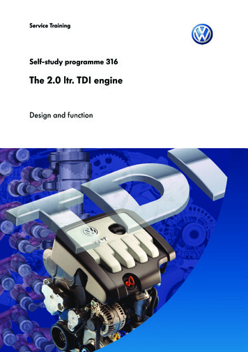
Service TrainingSelf-study programme 316The 2.0 ltr. TDI engineDesign and function
The days of sluggish and noisy diesel enginesthat, when started, startled the whole neighbourhood out of bed and left a trail of black smokewhen full throttle was applied are long gone.In order to meet the stricter emissions regulationsand to further reduce fuel consumption withgreater power output, Volkswagen uses the TDIengine generation with 4 valve technology.Driving performance, driving dynamics, drivingcomfort, economy and emissions have beenmarkedly improved due to the consistent furtherdevelopment of all the engine components, thecombustion procedure, the materials andprocesses and also the injection pressures.The 2.0 ltr. TDI engine was developed as the firstfour cylinder diesel engine with four valvetechnology in the Volkswagen Group for use inthe Touran, in the Golf 2004 and also in othervehicles yet to be introduced.S316 039NEWThis self-study programme shows the design andfunction of new developments!The contents will not be updated.2For current inspection, adjustment and repairinstructions, please refer to the relevant serviceliterature.ImportantNote
ContentsIntroduction . . . . . . . . . . . . . . . . . . . . . . . . . . . . . . . . . . .4Engine mechanics . . . . . . . . . . . . . . . . . . . . . . . . . . . . . .6Engine management. . . . . . . . . . . . . . . . . . . . . . . . . . 20Functional diagram . . . . . . . . . . . . . . . . . . . . . . . . . . . .38Service . . . . . . . . . . . . . . . . . . . . . . . . . . . . . . . . . . . . . 40Test yourself . . . . . . . . . . . . . . . . . . . . . . . . . . . . . . . . . 413
IntroductionThe 2.0 ltr./103 kW TDI engine with 4-valve technologyS316 011The 2.0 ltr./103 kW TDI engine is the first in a lineof new TDI engine generations with 4 valvetechnology from VOLKSWAGEN.A 100 kW version of the engine has alreadybeen introduced in the Volkswagen Touran.It is a further development of the 1.9 ltr./96 kWTDI engine. The increase in engine sizecompared with the standard engine wasachieved by resizing the bore.4The new 2.0 ltr./103 kW TDI engine features anewly developed cross-flow aluminium cylinderhead with two inlet and two exhaust valves percylinder.Further technical highlights are a switchablecooler for exhaust gas recirculation, a crankshaftsealing flange with integrated engine speedsender wheel and a new preglow system.
Technical dataEngine codeBKDType4-cylinder in-line engineDisplacement1968 cm3Bore81 mmStroke95.5 mmValves per cylinder4Compression ratio18:1Max. output103 kW at 4000 rpmMax. torque320 Nm at 1750 rpm to 2500 rpmEngine managementEDC 16 with unit injector systemFuelDiesel, at least 49 CNExhaust gas treatmentExhaust gas recirculation and oxidising catalytic converterEmissions 308020401000100020003000Engine speed (rpm)4000At an engine speed of between 1750 rpm and2500 rpm, the 2.0 ltr./103 kW TDI enginedevelops 320 Nm of torque.Its maximum output of 103 kW is reached at aspeed of 4000 rpm.Output (kW)Torque (Nm)Torque and power development diagram5000S316 0125
Engine mechanicsThe cylinder headVertically installed, centrally locatedRoller rocker arm forunit injectorunit injectorInlet camshaftExhaust camshaftKnock-out spindlesRoller rocker armfor valvesExhaust portS316 013The cylinder head of the 2.0 ltr. TDI engine is ofthe cross-flow type made from aluminium withtwo inlet and two exhaust valves per cylinder.The valves are installed vertically.The two overhead camshafts are driven togetherby a toothed belt.Inlet portVertically installed valvesIn addition to exhaust valve timing, the exhaustcamshaft is responsible for providing drive to theunit injectors.In addition to inlet valve timing, the inletcamshaft is responsible for providing drive to thetandem pump.Valve actuation is via roller rocker arms, whichare mounted on knock-out spindles.6
The bearing frameThe bearing frame is a compact component,pressure cast from aluminium. It is responsible forthe following functions: S316 014Lateral supportSpindle mounting of Mounting of the camshaftsSpindle mounting and guide for roller rockersto drive unit injectorsMounting of central connector for powersupplyMounting of cable channel for unit injectorsand glow plugs.Thanks to the overall design of the bearingframe, which features five strong lateralsupports, not only has rigidity in the cylinderhead been achieved but the acoustics of theengine have also been markedly improved.inlet camshaftCable channelS316 098Spindle mounting ofexhaust camshaftCentral connectorBearing support forroller rocker spindleFixture concept "bolt in bolt"Bearing frameCylinder headThe bearing frame is bolted directly in the boltheads of the cylinder head bolts at both innerrows by means of a "bolt in bolt" bondingconcept.This space saving concept of joining bearingframe and cylinder head to the engine block is aprerequisite for the low cylinder clearance.Cylinder headboltCylinder blockS316 1007
Engine mechanicsThe 4 valve technologyEach cylinder is allocated two inlet and twoexhaust valves, which are installed vertically.Shape, size and layout of the inlet and exhaustvalves are contributory factors for improvedvolumetric efficiency and better air/fuel mixtureflow.The vertically installed, centrally located unitinjectors can be found directly above the centralpiston crowns.This design positively affects the mixtureformation. The result is a reduction in fuelconsumption and lower exhaust emissions.Inlet portsExhaust portsS316 023For optimal flow properties through the inlet and exhaust ports, the valve pattern is rotated by 45 to thelongitudinal axis of the engine.Valve pattern rotated by 45 Normal layout of valvesLongitudinal axis ofengineExhaust portsInlet portsS316 0208S316 156
Drive for inlet and exhaust valvesDue to dimensional requirements in componentassembly, the four roller rocker arms differ in sizeand shape.Both camshafts for control of the inlet andexhaust valves are driven by a toothed belt.Valve actuation is via roller rocker arms, whichare mounted on a knock-out spindle.Inlet camshaftExhaust camshaftKnock-out spindleS316 019Knock-outspindleRoller rocker armExhaust valvesS316 033Inlet valves9
Engine mechanicsThe roller rocker armsRoller rocker armThese are mounted, to allow freedom ofmovement, on a knock-out spindle. The valveclearance compensator can be found directlyabove the valve shaft.Feed channelOil is supplied to the valve clearancecompensator from the knock-out spindle via afeed channel in the roller rocker arm. A floatingglide element installed between valve clearancecompensator and valve shaft, ensures an equaland balanced distribution of force.Valve clearancecompensatorGlide elementKnock-out spindleS316 021Valve shaftDesign and function of valve clearance compensatorThe valve clearance compensator comprises,among other things, of two parts:Plunger and cylinder. These are subjected toopposing forces.A plunger spring forces both parts apart so thatthe clearance is taken up between roller rockerarm and camshaft. The non-return valve servesas a means of filling and sealing the highpressure chamber.CamshaftCylinderPlungerNon-return valveRoller rockerOil reservoirarmHigh pressurechamberPlunger springFeed channelValve shaft ofinlet/exhaust valve10S316 168
Valve strokeWhen pressure is exerted on the roller rockerarm from the cam, the non-return valve closesand pressure is built up in the high pressurechamber.The valve clearance compensator acts as a solidelement when the valve opens, as the oil cannotbe compressed in the high pressure chamber.S316 170S316 320Compensation of valve clearanceClearanceThe cam no longer exerts pressure on the rollerrocker arm and the inlet or exhaust valve isclosed. Pressure in the high pressure chamberdrops. The plunger spring forces the cylinder andplunger apart so that clearance is taken upbetween roller rocker arm and camshaft.The non-return valve opens to let oil flow into thehigh pressure chamber.S316 172S316 322The valve seat ringsAdditionalValve seat widthchamferValve seat ringValve seatS316 018The valve seat forms the seal from thecombustion chamber.To permit a greater degree of sealing pressure,and thereby a tighter seal in the contact areabetween valve seat and valve seat ring, the widthof the valve seat is reduced by an additionalchamfer.This additional chamfer also ensures good swirlproperties of the intake air.Valve seat rings should not be reworked, otherwise the swirl effect of the intake air, and therebythe mixture formation, would be affected considerably. Only grinding in to match surfaces ispermissible.11
Engine mechanicsThe pistonThe pistons of the 2.0 ltr. TDI engine have acentrally located combustion recess. Thanks tothis recess, a good swirl effect of the intake air isachieved, also resulting in an optimal mixtureformation.Combustion recessValve face recessA reduction in the valve face recess and a pistoncrown depth of just 9 mm made it possible toreduce the dead area above the piston crown,and thus also the level of harmful emissions.Piston crown depthCoolingchannelS316 027Dead areaThe dead area is the space above the pistoncrown in the combustion chamber where accessto the air and fuel mixture is poor. In this area,the air and fuel mixture does not burn fully.Dead area,valve face recessS316 228Dead area,piston crown sideS316 226Cooling channelThe piston has an undulating cooling channel.Thanks to this cooling channel, the temperature isreduced in the area of the piston rings and pistoncrown.CoolingchannelThe undulating shape allows a greater surfacearea of the cooling channel, thus increasingtransfer of heat from the piston to the oil. In thisway, cooling efficiency is improved.S316 03512
Offset piston pin axisPiston centre lineOffset axisOffset piston pin axis means that the bearingpoint of the piston is not central. This measureserves as a means of noise reduction, as rockingof the piston at top dead centre is reduced.S316 182When the conrod is at an angle, pressure is exerted on both sides of the piston from the reciprocatingmotion of the crankshaft, which pushes the piston against the cylinder walls.S316 230At top dead centre, the pressure on the pistonchanges sides. Here, the piston is pushed againstthe opposite cylinder wall in a rocking motion,which causes the noise. As a measure to reducethis noise, the piston pin axis is moved from thecentre line.S316 232S316 234Thanks to the offset, the piston changes sidesbefore top dead centre, thereby preventingpressure from being exerted, and it supportsitself against the opposite cylinder wall.13
Engine mechanicsThe toothed belt driveBoth camshafts and the coolant pump are drivenby the crankshaft via a toothed belt.CamshaftsCoolant pumpToothed beltCrankshaftToothed beltThe 30 mm wide toothed belt features a rearcord support backing made from polyamide.The cord support backing reduces wear of thebelt edges.S316 054Basic material madeCord support backingfrom rubbermade from polyamidePly cords made fromglass fibreBelt facing madeS316 162from polyamideToothed belt guardTo insulate against noise, the toothed belt guardhas a woven lining on the inside made from softpolyamide fibres.Toothed belt guardPolyamide fibresS316 238PlasticS316 23614
The tandem pumpDue to the new cylinder head design, there is anew type of tandem pump.The tandem pump comprises of vacuum pumpand fuel pump. It is driven by the inlet camshaft.S316 022Vacuum pumpFuel pumpVacuum pumpIntake sideAir inlet fromVanevacuum systemAir intakeVaneRotorRotorCompressed airAir outletto cylinder head(flap valve)Oil channelPressure sideS316 122The vacuum pump consists of a rotor (offset fromthe middle) and a moving vane made fromplastic, which separates the vacuum pump intotwo compartments.The vane continually changes its position due tothe rotation of the rotor. In this way, onecompartment becomes bigger and the otherbecomes smaller.S316 120On the intake side, air is drawn from the vacuumsystem, which is pumped in the cylinder head viaa flap valve. The vacuum pump is supplied withoil via a channel to the cylinder head. The oilserves as a means of lubricating the rotor and asa fine seal between vane and pump housing.15
Engine mechanicsFuel pumpPressure control valve,fuel supplySieveReturn to tankSupply from tankPressure control valve,fuel returnReturn from unitinjectorsSupply to unitinjectorsS316 124The fuel pump works in the same way as aninterior gear pump. The principle of fuelinduction and supply is shown by the movementof fuel marked red within the pump in theindividual illustrations.Fuel pressure is regulated by a pressure controlvalve in the fuel supply path.S316 12616It reaches a maximum of 11.5 bar at an enginespeed of 4000 rpm.The pressure control valve in the fuel supply pathmaintains fuel return pressure at approx. 1 bar.In this way, an equal and balanced distributionof pressure is assured at the solenoid valves ofthe unit injectors.S316 128
The unit injectorFor the 2.0 ltr. TDI engine with 4 valvetechnology, the unit injector was furtherdeveloped.Characteristics of the unit injector: More streamline and compact designFixed in cylinder head by means of two boltsIncrease in injection pressure at part throttleRetraction plunger brake to reduce injectionnoiseRedesigned, tapered unit injector seat incylinder head.S316 158Fitting locationThe unit injector can be found in the cylinderhead. It is in the vertical position and locateddirectly above the centre of the piston crown.AttachmentAttachment of the unit injector is via two bolts.This choice of bolted connection, practically freeof lateral stress, reduces the transfer of structuralnoise from the unit injector to the cylinder head.Securing boltsS316 14417
Engine mechanicsTapered seatThe redesigned tapered seat of the unit injectorin the cylinder head allows the unit injector to becentred optimally. The new sealing conceptbetween injector and cylinder head has beenmodified from a ground surface with washer to atapered seat.CylinderheadAs a result, the heat insulating seal and lowerO-ring are no longer fitted.Tapered seatS316 064S316 060Retraction plunger brakeThe retraction plunger can be found betweenpump and injector and controls the quantity andperiod of pilot injection.To reduce injection noise, the unit injector isequipped with a retraction plunger brake. Onthe unit injector system, injection noise isgenerated by: Rapid pressure increase and release in thehigh pressure chamberCavity caused as a result of pressure release(cavitation)Mechanical impact from:-Retraction plunger-Valve pin-Injector pin.S316 060Retraction plungerS316 174An efficient and realistic aid towards noisereduction is a measure to brake the retractionplunger before it reaches its mechanical stop,i.e. the retraction plunger brake.18With the retraction plunger brake, the hydraulicpressure above the retraction plunger is reducedbefore the retraction plunger hits its mechanicalstop.
FunctionGuide cylinder ofretraction plungerOn the retraction plunger brake, the guidecylinder of the retraction plunger features threelevel surfaces (triangle) and a control shoulder.Before retraction begins, the retraction plunger isin the closed position.TriangleRetraction plungerUnit injector bodyS316 090As soon as the plunger moves downwards, highpressure is applied to the large retractionplunger diameter, thus allowing rapid shutoff ofpilot injection.Large retractionplunger diameterS316 092Control shoulderAs soon as the guide cylinder reaches the controlshoulder above the three flat surfaces, supply tothe retraction plunger compression chamber isstopped. This reduces pressure at the largeretraction plunger diameter abruptly. In this way,the retraction plunger makes contact moresmoothly and impact noise is reduced.Retraction plungerpressure chamberS316 09419
Engine managementSystem overviewSensorsG28 Engine speed senderG40 Hall senderG79 Accelerator pedal position sender 1G185 Accelerator pedal position sender 2CAN busG70 Air mass meterG62 Coolant temperature senderG83 Coolant temperature senderradiator outletG81Fuel temperature senderJ248 Diesel direct injectionsystem control unitG42 Intake air temperature senderFF47Brake light switchBrake pedal switch for CCSDiagnosis connectorG476 Clutch position senderG3120Charge air pressure sender
ActuatorsN240N241N242N243Unit injector valve, no. 1 cylinderUnit injector valve, no. 2 cylinderUnit injector valve, no. 3 cylinderUnit injector valve, no. 4 cylinderSolenoid valve block with:N18 Exhaust gas recirculation valveN345 EGR cooler changeover valveN75 Charge pressure control solenoid valveV157 Intake manifold flap motorJ17G6Fuel pump relayFuel pumpJ293 Radiator fan control unitV7Radiator fanV35 Radiator fan, rightS316 110J370Q10Q11Q12Q13Glow plug control unitGlow plug 1Glow plug 2Glow plug 3Glow plug 421
Engine managementThe control units in the CAN data busThe schematic diagram below shows the way thediesel direct injection control unit J248 isincluded in the CAN data bus structure of thevehicle.Information is sent between control units via theCAN data bus.For example, the diesel direct injection controlunit receives the speed signal from a speedsensor via the ABS control 234J248J285J519J527J533J74322ABS with EDL control unitAutomatic gearbox control unitAirbag control unitDiesel direct injection system control unitControl unit with display unit indash panel insertOnboard power supply control unitSteering column electronics control unitData bus diagnosis interfaceDirect shift gearbox mechatronicsColour codes/key "Drive train" CAN data bus "Convenience" CAN data bus "Infotainment" CAN data busS316 220
The engine speed sender G28The crankshaft sealing flange on the flywheelside is combined with the engine speed senderwheel. The seal in the sealing flange is made ofpolytetrafluorethylene (PTFE).Engine speedsender G28The engine speed sender is a Hall sender. It isbolted to the crankshaft sealing flange housing.The sender wheel is pressed into exactly the rightposition on the crankshaft flange.S316 036SealThe sender wheel consists of a steel ring, ontowhich a rubber composite material is sprayed.In this rubber composite material is a largequantity of metal shavings, which aremagnetised alternately to north and south.As a reference mark for the engine speed senderthere are two wider areas on the sender wheelthat are magnetised to north.This results in a 60-2-2 sender wheel.S316 040North poleSouth poleSignal applicationEffects of signal failureThe signal from the engine speed sender allowsthe engine control unit to determine the speed ofthe engine and the exact position of thecrankshaft. With this information, the quantity ofinjection and start of injection are calculated.In the event of engine speed sender failure, theengine will continue to operate in emergencyrunning mode. The speed of the engine isthereby limited to between 3200 rpm and3500 rpm.23
Engine managementThe Hall sender G40The Hall sender is attached to the cylinder headbelow the inlet camshaft. It picks up the positionof the camshaft via a quick start sender wheel.S316 044The sender wheel on the camshaft is a newdesign. In conjunction with the Hall sender G 40(camshaft), an emergency running mode is madepossible in which the engine can continue to runeven in the event of engine speed sender failure.Around the circumference of the sender wheelare 4 segments split into 6 , 12 , 18 and 24 camshaft angles for cylinder assignment.A further segment with a 45 camshaft angleserves as a means of cylinder assignment foremergency running mode.TDC cylinder 4TDC cylinder 3TDC cylinder 1TDC cylinder 2S316 04624Signal applicationEffects of signal failureWith the signal from the Hall sender, the exactposition of the camshaft in relation to thecrankshaft is determin
technology from VOLKSWAGEN. A 100 kW version of the engine has already been introduced in the Volkswagen Touran. It is a further development of the 1.9 ltr./96 kW TDI engine. The increase in engine size compared with the standard engine was achieved by resizing the bore. The new 2.0 ltr./103 kW TDI engine features aFile Size: 1MB