Transcription
Module 6Engine Control Module (ECM)Author: Grant SwaimE-mail: sureseal@nr.infi.netURL: www.tech2tech.netPhone: (336) 632-9882Fax: (336) 632-9688Postal Address: Tech-2-Tech WebsitePO Box 18443Greensboro, NC 27419Physical Address: 220-4 Swing RdGreensboro, NC 27409Last Update: April 2000IMPORTANT - READ !Do not read or study this information unless you agree to thefollowing conditions:The information in this training module is the intellectualproperty of N. Grant Swaim and is copyrighted by Sure SealProducts Inc.Subscribers to the Tech-2-Tech website, and persons participating in Tech-2-Tech’s on-line training program are entitledto read this material on-line.You may also click on the “save” icon on the Acrobat viewerand save a copy to your local computer. You may save acopy of this file on one computer and it must be viewed fromthat one computer.You may also print one copy of this file for your viewing. Ifthe printed copy becomes illegible, or lost, an additionalcopy may be printed.Tech-2-Tech offers the following training modules in printed manual, CD-ROM, and on-line formats.PGMFI Training Modules The PGMFI System Overview—Part 1The PGMFI System Overview—Part 2PGMFI Flash Type DTCsInputs / Outputs—Part 1Inputs / Outputs—Part 2Engine Control ModuleAir Flow / MAP Sensor—Base Inj Pulse WidthFuel Delivery SystemClosed Loop Strategies—TheoryClosed Loop Strategies—Case StudiesThermistor InputsThrottle Position SensorEGR Valve Lift SensorMAP / BARO SensorIgnition InputsVehicle Speed SensorOxygen SensorLean Air Fuel SensorMiscellaneous Input SignalsFuel Injectors—Multi-Port InjectionFuel Injectors—Dual Point InjectionIgnition System—OutputsIdle Air Control ValveOBD-II Training Modules On Board Diagnostics—General OverviewDiagnostic Trouble CodesMIL / Freeze FrameScan ToolScan Tool—AdvancedMonitor Tests—OverviewComprehensive Component MonitorCatalyst MonitorEGR MonitorEvaporative MonitorFuel System MonitorMisfire MonitorOxygen Sensor MonitorOxygen Sensor Heater Monitor“P” CodesMiscellaneous Training Material Glossary of Terms2000 - All Rights Reserved Sure Seal Products Inc - Greensboro, NC
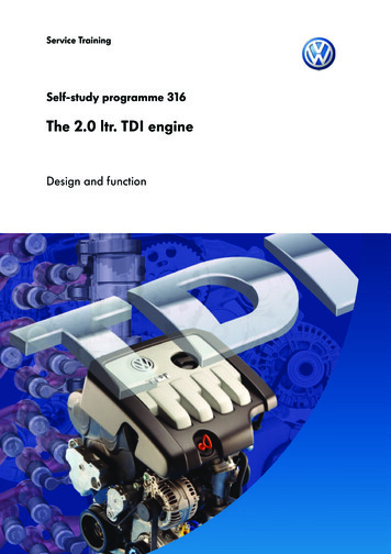
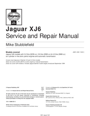
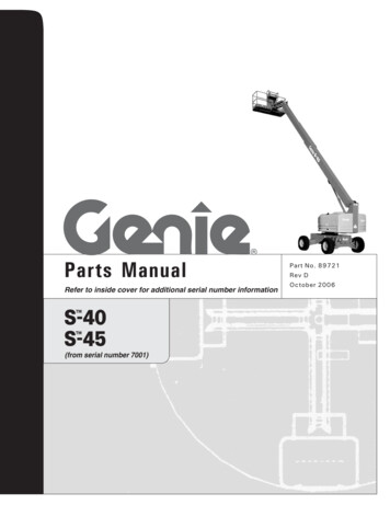
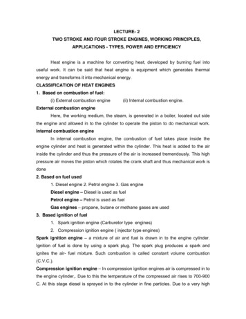
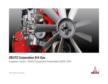
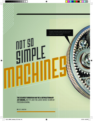
Visit Our Website: www.tech2tech.netPage6-16 Engine Control Module6.1Control Modules - General OverviewImage 6-1 PCM Internal ComponentsAt the heart of the PGMFI andOBD-II system is the enginecontrol module (ECM) or powertrain control module (PCM). Thedifference between the twomodules is in the systems theyeach control.An ECM only controls enginefunctions such as fuel and ignition timing control. The ECMhandles no significant transmission functions.Some automatic transmissionequipped models will have a separate control module for the transmission. Thismodule is called a transmission control module (TCM). A TCM is shown in Image 6-2. A TCM is physically smallerImage 6-2 TCM Componentsthan an ECM or PCM.Some models have one control modulefor both engine and transmission control. This module is called a PCM. APCM with the top removed is shown inImage 6-1.In the beginning these modules wereonly used to control fuel, ignition timing, and transmission functions. Latermodel Hondas use the ECM/PCM toalso manage systems such as A/C compressor control and cooling fan activation.6.2Input SignalsImage 6-3 Input/Output Terminal GaugeA control module receives analog inputsignals from the sensors and then controls several load devices such as fuelinjectors, IAC valve, and solenoidvalves. The incoming signals have verylow current flow, however, the load de- All Rights Reserved 2000 Sure Seal Products IncThis manual printed 4/9/00 from the file pgmfiobd 002.
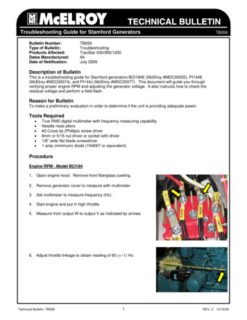
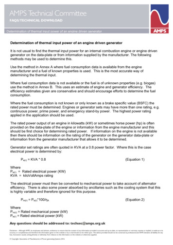
Page6-2Visit Our Website: www.tech2tech.netIllustration 6-1 5-volt Referencevices can have a significant load requirement.The difference in current carrying capacity canbe seen in the gauge of the connector terminalsshown in Image 6-3.The incoming signals have to be conditioned,strengthened and converted to a digital formatbefore the processor can use the information. Alarge part of the electronic components shown inImage 6-1 are used to perform these tasks.Many of the signals used by the control modules are based on a 5-volt referencesignal as shown in Illustration 6-1. Most of the 5-volt reference inputs produce avoltage from about .5v to 4.5v, which represents its range of input.In addition to 5-volt reference inputs the control module also receives signalsfrom these types of sensors. 6.3Temperature sensing thermistorsOn/Off SwitchesVoltage producing (O2 Sensor)DC Square wave signalsAC wave signalsControl Module Information TablesIllustration 6-2 Honda Ignition Timing MapThe ECM/PCM takes all the input information and processes itto determine the proper outputs.Not all inputs are used in everyoutput decision. The authorityeach input has over a given output varies widely.Most of the output decisions arebased on programmed internalinformation. The information isoften stored in the form of a matrix. These are sometimes referred to as look-up tables or data maps.Illustration 6-2 is a graph drawn from an actual Honda ignition timing data table.This Honda had 14 ignition timing tables as shown by the 14 graphs. TheECM/PCM picked a timing table based on MAP voltage. Each table was a gridwith RPM on one axis and ignition timing on the other axis. All Rights Reserved 2000 Sure Seal Products IncThis manual printed 4/9/00 from the file pgmfiobd 002.
Visit Our Website: www.tech2tech.netPage6-3In summary the ECM/PCM had 14 different ignition timing profiles. The profileswere chosen based on engine load. Note that the ignition timing advance is notinfinitely changed; it is changed at specific RPMs and by a set amount.The information stored in a Honda ECM/PCM cannot be changed. The Hondacontrol modules cannot be reprogrammed with new information. If Honda needsto make a change in the fuel or ignition timing controls, the ECM/PCM has to bechanged out.6.4Control Module OutputsIllustration 6-3The ECM/PCM directly controls several outputs,such as ignition igniter trigger, fuel injectors, andidle air control (IAC) valve.Illustration 6-3, on the left, shows the typical output circuitry. The PCM/ECM controls the load devices by providing a ground to its circuit. Bycontrolling the ground side of the circuit, theECM/PCM is not damaged by excessive current ifa short to ground occurs in the circuit.On OBD-II equipped models the outputs are alsochecked for functionality. When a device is activated by the ECM/PCM, an “output state monitor” checks the circuit. This specialcircuitry confirms that the correct current flowed when the load is activated.Image 6-4 Injector DriversA transistor, often called a driver,grounds the load current when activatedby the processor. A transistor can bethought of as an electronic relay. Asmall current from the processor activates the transistor to ground the loadcircuit, which can be significant.Image 6-4, on the left, shows the injector drivers of a dual point injectionHonda. Drivers are typically bolted tothe inside of the module case. Transistors tend to get hot when they are operating. They are bolted to the module’saluminum case to help in heat dissipation. The two transistors shown in Image 6-4are sandwiched between the module case and an additional heat sink. All Rights Reserved 2000 Sure Seal Products IncThis manual printed 4/9/00 from the file pgmfiobd 002.
6-4Page6.5Visit Our Website: www.tech2tech.netControl Module Service IssuesThe control modules used by Honda are very reliable. It is very rare to have anECM/PCM failure; however, there are a few service issues to be aware of.6.5.1 Water Damaged Control ModulesImage 6-5 Water Damaged PCMOne of the biggest problems with HondaECM/PCMs is that in most models theyare located very low in the car. Somemodels have them actually mounted flaton the floorboard. This makes them susceptible to water damage.There are many ways, other than floodwaters, to get enough water inside thecar to water damage the modules. Someof the more common sources of waterare: leaking radio antenna, leakingmoonroof drains and leaking wind-shields.An ECM/PCM that has been water damaged should be replaced. Initially the effects of water damage may not be obvious. Typically the circuit board of a waterdamaged ECM/PCM will develop a chalky residue in time. This residue is a formof corrosion and will eventually damage solder joints. Image 6-5 shows thischalky residue.If you suspect a module has been subjected to water, pull the top and bottom covers and look for signs of water damage. In addition to moisture still present andthe chalky residue; look for rust on the inside of the covers.The biggest problem with water damaged ECMs is that they can develop problems later. When this happens it is oftenImage 6-6 Damaged ECM/PCMdifficult to diagnose. Most commercialmodule rebuilders will not repair anECM/PCM that has been water damaged.6.5.2Damaged ECM/PCM CircuitBoardsIt is very rare for a Honda ECM/PCM tofail. A hard failure, such as a burnt circuit board competent, could be an indication of excessive current. Excessive All Rights Reserved 2000 Sure Seal Products IncThis manual printed 4/9/00 from the file pgmfiobd 002.
Visit Our Website: www.tech2tech.netPage6-5current flow could be caused by a failure in a load device or external circuitry.Image 6-6 shows two burnt electronic components on a Honda TCM.Before replacing a ECM/PCM with a hard failure, the loads and external circuitsshould be checked for excessive current first. Failure to do this could result indamaging the replacement ECM/PCM with excessive current. Simply look at aschematic and identify all the loads the ECM/PCM controls. Identify the loadgrounds in the ECM/PCM connector. With the ECM/PCM disconnected and thekey on engine off (KOEO) ground each load individually and check for excessiveloads.6.5.3Poor ECM/PCM GroundsVarious load devices are directly controlled by the ECM/PCM. Some of the components that are controlled are the fuel injectors, the IAC valve, various solenoids,and the igniter trigger. These components are supplied with positive voltage andthe ECM/PCM activates the devices by grounding them.For example when the ECM/PCM’s processor activates a fuel injector, it triggersa transistor, which in turn grounds the injector. The ground(s) that the ECM/PCMuses is actually external of the module. One or more of the ECM/PCM wire(s) is aground wire(s). If there is excessive voltage drop across ECM/PCM grounds, thevoltage applied to the load devices will be reduced by this amount. The reducedvoltage applied to the loads can cause a malfunction or failure.These ECM/PCM grounds typically attach to the powertrain. Some models usedone of the thermostat bolts as the grounding point for the module grounds. Thesegrounds would often drop too much voltage and cause problems.6.5.4 The Effects of Installing an Incorrect ECM/PCMCaution should be used when changing out ECM/PCM units, to make sure thecorrect unit is being used. While this is more of a problem when using a usedmodule, a new module could be ordered incorrectly, too.New features were added almost yearly and did not necessarily coincide with thebody changes. For instance Honda added the vehicle speed sensor (VSS) input tothe 88 Accord ECM. If the 1988 Accord ECM was installed into a 1987 Accord,which is the same generation and engine, it would set a VSS diagnostic troublecode (DTC) since no VSS signal would be present.If a car starts setting new DTCs right after swapping out a ECM/PCM, suspectthat the module is not compatible with the car. All Rights Reserved 2000 Sure Seal Products IncThis manual printed 4/9/00 from the file pgmfiobd 002.
and save a copy to your local computer. You may save a copy of this file on one computer and it must be viewed from that one computer. You may also print one copy of this file for your viewing. If the printed copy becom