Transcription
RedboxUser Handbook No 2Matching Converters, DistributionAmplifiers & Headphone AmplifiersRB-UL1Single stereo unbalanced to balanced converterRB-UL2Dual stereo unbalanced to balanced converterRB-UL4Quad stereo unbalanced to balanced converterRB-LU4Quad stereo balanced to unbalanced converterRB-BL2Single stereo bi-directional matching converterRB-BL4Dual stereo bi-directional matching converterRB-PA2Dual stereo RIAA phono amplifierRB-LI2Stereo line isolation unitRB-PLI66 way mono passive line isolation unitRB-DA66 way stereo distribution amplifierRB-DA6G6 way stereo distribution amplifier with outputgain controlRB-DA4x54 input, 4 x 5 output distribution amplifier/mixerRB-DDA6A6 way stereo AES/EBU digital distribution amplifierRB-DDA6S6 way stereo S/PDIF digital distribution amplifierRB-DDA6W6 way word clock digital distribution amplifierRB-HD1Stereo headphone amplifierRB-HD2Dual stereo headphone amplifierRB-HD66 way stereo headphone distribution amplifierRB-DHD6Digital 6 way stereo headphone distribution amplifier
Revision 2.05 July, 2009 Sonifex Ltd, 2000-9All Rights ReservedSonifex Ltd, 61, Station Road, Irthlingborough,Northants, NN9 5QE, England.Tel : 44 (0)1933 650 700Fax : 44 (0)1933 650 726Email : sales@sonifex.co.uk or technical.support@sonifex.co.ukWeb : http://www.sonifex.co.ukInformation in this document is subject to change without notice and does not representa commitment on the part of Sonifex Ltd. Sonifex Ltd shall not be liable for any loss ordamage whatsoever arising form the use of information or any error contained in thismanual.No part of this manual may be reproduced or transmitted in any form or by any means,electronic or mechanical, including photocopying, recording, or information storage andretrieval systems, for any purpose other than the purchaser’s personal use, without theexpress written permission of Sonifex Ltd.Unless otherwise noted, all names of companies, products and persons contained herein arepart of a completely fictitious adaptation and are designed solely to document the use ofSonifex products.bRedbox User Handbook No 2
CONTENTSWarrantyiiiiiiiSafety InformationiiiSafety of Mains Operated EquipmentVoltage Setting ChecksFuse RatingPower Cable and ConnectionOrdering the Correct Mains LeadiiiiiiiiiivivInstallation InformationivAtmosphereElectromagnetic RadiationFitting RedboxesWEEE & RoHS Directives - Sonifex StatementivivivviMATCHING CONVERTERS1RB-UL1 Single, RB-UL2 Dual & RB-UL4 Quad Stereo UnbalancedTo Balanced Converters1IntroductionSystem Block DiagramRear Panel Connections and OperationRCA Phono Inputs (Left and Right)Outputs (Left and Right)Output Level AdjustmentTechnical Specifications112333425RB-LU4 Quad Stereo Balanced To Unbalanced ConverterIntroductionSystem Block DiagramRear Panel Connections and OperationInputs 1-4 (Left and Right)RCA Phono Outputs 1-4 (Left and Right)Output Level AdjustmentTechnical Specifications567777839RB-BL2 Single & RB-BL4 Dual Bi-Directional Matching ConverterIntroductionSystem Block DiagramRear Panel Connections and OperationBalanced to Unbalanced ConnectionsInputs 1 (& 3) (Left & Right)RCA Phono Outputs 1 (&3) (Left & Right)Output Level AdjustmentUnbalanced to Balanced ConnectionsRCA Phono Inputs 2 (& 4) (Left & Right)Outputs 2 (& 4) (Left & Right)Technical SpecificationsRedbox User Handbook No 2CON T E N TSWarranty and Liability - important the purchaser is advised to read this clauseUnpacking the RedboxReturning the Warranty Card910101111111111111112c
CO N T E N TSCON T E N TS4RB-PA2 Dual Stereo RIAA Phono Amplifier13IntroductionSystem Block DiagramRear Panel Connections and OperationRCA Phono Inputs (Left and Right)Outputs (Left and Right)Output Level AdjustmentPick-up Grounding PostTechnical Specifications1313141414141415516RB-LI2 Stereo Line Isolation UnitIntroductionSystem Block DiagramRear Panel Connections and OperationInputsIsolated OutputsLoop OutputsOutput Level AdjustmentInternal JumpersTechnical Specifications161617171717171818619RB-PLI6 6 Way Mono Passive Line Isolation UnitIntroductionSystem Block DiagramRear Panel Connections and OperationInputsOutputsGround-link Internal JumpersTechnical Specifications19192020202021AUDIO DISTRIBUTION AMPLIFIERS7RB-DA6 & RB-DA6G 6 Way Stereo Distribution Amplifier222324242424242525826RB-DA4x5 4 Input, 4 x 5 Output Distribution Amplifier/MixerIntroductionSystem Block DiagramRear Panel Connections and OperationAudio Inputs 1-4D-Type Audio Output Groups 1-4Monitor LEDsInput Level AdjustmentOutput Level AdjustmentRouting SelectionAlignment Test ToneTechnical Specificationsd22IntroductionSystem Block DiagramConnections and OperationInputs (Left & Right)Stereo Outputs 1-6 (Mono Outputs 1-12)Input Gain Control (RB-DA6)Output Gain Control (RB-DA6G)Stereo/Mono OperationTechnical Specifications2627272728282828282929Redbox User Handbook No 2
CON TEN TS9RB-DDA6A 6 Way Stereo AES/EBU Digital Distribution Amplifier andRB-DDA6S 6 Way Stereo S/PDIF Digital Distribution Amplifier30IntroductionSystem Block DiagramsRear Panel Connections and OperationsAES/EBU InputAES/EBU OutputsS/PDIF InputS/PDIF OutputsTechnical tem Block DiagramRear Panel Connections and OperationsWord Clock InputWord Clock OutputsTechnical Specifications353637373737HEADPHONE DISTRIBUTION AMPLIFIERS11 RB-HD1 Stereo Headphone Amplifier & RB-HD2 DualHeadphone Amplifier38IntroductionSystem Block DiagramsFront Panel Connections and ControlsStereo Outputs 1-2 (Mono Outputs1-2)Volume Level ControlStereo Outputs 1-2 (Mono Outputs 1-2)Channel Volume ControlsRear Panel Connections and OperationMain Stereo Inputs (Left and Right)Stereo Input Gain Adjustment (RB-HD1)Stereo/Mono OperationMono Mix Input (RB-HD1)Mono Mix Input Gain Adjustment (RB-HD1)Local/Remote Control Operation (RB-HD1)Remote Connector (RB-HD1)Technical Specifications3839404040404041414142424242424312 RB-HD6 6 Way Headphone Distribution Amplifier44IntroductionSystem Block DiagramRear Panel Connections and OperationStereo Input (Left and Right)Stereo/Mono OperationChannel Insertion Inputs/Parallel OutputsRemoving the Equipment CoversConfiguring Insert Inputs/Parallel OutputsFront Panel Connections and ControlsStereo Outputs 1-6 (Mono Outputs 1-6)Master Level ControlChannel Volume ControlsTechnical Specifications44454646464646474747484848Redbox User Handbook No 2CON T E N TS10 RB-DDA6W 6 Way Word Clock Distribution Amplifiere
CON T E N TSCO N T E N TSf13 RB-DHD6 Digital 6 Way Headphone Distribution Amplifier49IntroductionSystem Block DiagramFront Panel Indicators & ControlsSync & Power IndicatorHeadphone OutputsVolume ControlRear Panel Connections and OperationAES/EBU InputS/PDIF InputStatus Select SwitchesDigital Input Select ButtonTechnical Specifications49494950505050505050515114 Connectors & Cabling52XLR 3 Pin ConnectorsRCA Phono Connectors¼” Jack ConnectorD-Type Connectors5252525315 Glossary54Redbox User Handbook No 2
FIGURESFiguresFig A: Packing List.iiFig B: Mains Cable Wire ColoursivFig C: Mains Lead Table.ivFig D: RB-RK1Small Redbox Front Rack-mount Kit .vFig E: RB-RK2 Small Redbox Rear Rack-mount Kit.vvFig 1-1: RB-UL1 & RB-UL2 Front Panel.1Fig 1-2: RB-UL4 Front Panel.1Fig 1-3: Block Diagram For a Single Channel (x2 for RB-UL2, x4 for RB-UL4).1Fig 1-4: RB-UL1 Rear Panel.2Fig 1-5: RB-UL2 Rear Panel.2Fig 1-6: RB-UL4 Rear Panel.2Fig 2-1: RB-LU4 Front Panel.5Fig 2-2: RB-LU4 Block Diagram.6Fig 2-3: RB-LU4 Rear Panel.7Fig 3-1: RB-BL2 Front Panel.9Fig 3-2: RB-BL4 Front Panel.9Fig 3-3: RB-BL2/BL4 Block Diagram Single Stereo Channel.10Fig 3-4: RB-BL2 Rear Panel.10Fig 3-5: RB-BL4 Rear Panel.11Fig 4-1: RB-PA2 Front Panel.13Fig 4-2: RB-PA2 Block Diagram For a Single Stereo Channel.13Fig 4-3: RB-PA2 Rear Panel.14Fig 5-1: RB-LI2 Front Panel.16Fig 5-2: RB-LI2 System Block Diagram.16Fig 5-3: RB-LI2 Rear Panel.17Fig 5-4: RB-LI2 Jumper Positions on the PCB.18Fig 6-1: RB-PLI6 Front Panel.19Fig 6-2: RB-PLI6 System Block Diagram.19Fig 6-3: RB-PLI6 Rear Panel.20Fig 6-4: RB-PLI6 Ground-link Jumper Settings.20Fig 7-1: RB-DA6 Front Panel.22Fig 7-2: RB-DA6G Front Panel.22Fig 7-3: RB-DA6 Block Diagram.23Fig 7-4: RB-DA6G Block Diagram.23Fig 7-5: RB-DA6 & RB-DA6G Rear Panel.24Fig 7-6: RB-DA6 Front Panel.24Fig 7-7: RB-DA6G Front Panel.25Fig 8-1: RB-DA4x5 Front Panel.26Fig 8-2: RB-DA4x5 Block Diagram.27Fig 8-3: RB-DA4x5 Rear Panel.27Fig 8-4: RB-DA4x5 Audio Output Group15-Way D-Type Plug.28Redbox User Handbook No 2FI G U RE SFig F: RB-RK3 Large Redbox Rear Rack-mount Kit.g
FI G U RE SFIGUREShFig 8-5: RB-DA4x5 Pinout for Audio Output Group Connector.28Fig 8-6: RB-DA4x5 Routing Selection Switch.28Fig 8-7: RB-DA4x5 Routing Selection Switch Functions.29Fig 9-1: RB-DDA6A/S Front Panel.30Fig 9-2: RB-DDA6A System Block Diagram.31Fig 9-3: RB-DDA6S System Block Diagram.32Fig 9-4: RB-DDA6A Rear Panel.33Fig 9-5: RB-DDA6S Rear Panel.33Fig 10-1: RB-DDA6W Front Panel.35Fig 10-2: RB-DDA6W System Block Diagram.36Fig 10-3: RB-DDA6W Rear Panel.37Fig 11-1: RB-HD1 Front Panel.38Fig 11-2: RB-HD2 Front Panel.38Fig 11-3: RB-HD1 Block Diagram.39Fig 11-4: RB-HD2 Block Diagram.39Fig 11-5: RB-HD1 Front Panel Controls.40Fig 11-6: RB-HD2 Front Panel Controls.40Fig 11-7: RB-HD1 Rear Panel.41Fig 11-8: RB-HD2 Rear Panel.41Fig 11-9: RB-HD1 Remote Connector42Fig 12-1: RB-HD6 Front Panel.44Fig 12-2: RB-HD6 Block Diagram.45Fig 12-3: RB-HD6 Rear Panel.46Fig 12-4: RB-HD6 Jumper Assignments.47Fig 12-5: RB-HD6 Jumper Positions.47Fig 12-6: RB-HD6 Front Panel Controls.47Fig 12-7: RB-HD6 Master Level Control.48Fig 13-1: RB-DHD6 Front Panel.49Fig 13-2: RB-DHD6 System Block Diagram.49Fig 13-3: RB-DHD6 Front Panel Controls.49Fig 13-4: RB-DHD6 Rear Panel.50Fig 13-5: RB-DHD6 Status Select Switches.50Fig 14-1: XLR Connectors.52Fig 14-2: RCA Phono Connector.52Fig 14-3: ¼” Jack Connector.52Fig 14-4: 25 Way D-Type Connectors.53Fig 14-5: 15 Way D-Type Connectors.53Fig 14-6: 9 Way D-Type Connectors.53Redbox User Handbook No 2
WARR ANT YWarrantyWarranty and Liability - important the purchaser is advised to read this clause(a)The Company agrees to repair or (at its discretion) replace Goods which are found tobe defective (fair wear and tear excepted) and which are returned to the Companywithin 12 months of the date of despatch provided that each of the followingare satisfied:Notification of any defect is given to the Company immediately upon itsbecoming apparent to the Purchaser;(ii)The Goods have only been operated under normal operating conditions andhave only been subject to normal use (and in particular the Goods must havebeen correctly connected and must not have been subject to high voltage orto ionising radiation and must not have been used contrary to the Company’stechnical recommendations);(iii)The Goods are returned to the Company’s premises at the Purchaser’s expense;(iv)Any Goods or parts of Goods replaced shall become the property of theCompany;(v)No work whatsoever (other than normal and proper maintenance) has beencarried out to the Goods or any part of the Goods without the Company’s priorwritten consent;(vi)The defect has not arisen from a design made, furnished or specified by thePurchaser;WA RR A N T Y(i)(vii) The Goods have been assembled or incorporated into other goods only inaccordance with any instructions issued by the Company;(viii) The defect has not arisen from a design modified by the Purchaser;(ix)The defect has not arisen from an item manufactured by a person other thanthe Company. In respect of any item manufactured by a person other than theCompany, the Purchaser shall only be entitled to the benefit of any warranty orguarantee provided by such manufacturer to the Company.(b)In respect of computer software supplied by the Company the Company does notwarrant that the use of the software will be uninterrupted or error free.(c)The Company accepts liability:(i)For death or personal injury to the extent that it results from the negligence ofthe Company, its employees (whilst in the course of their employment) or itsagents (in the course of the agency);Redbox User Handbook No 2i
WA R R A N T YWA RR A N T Y(ii)For any breach by the Company of any statutory undertaking as to title, quietpossession and freedom from encumbrance.(d)Subject to conditions (a) and (c) from the time of despatch of the Goods from theCompany’s premises the Purchaser shall be responsible for any defect in the Goodsor loss, damage, nuisance or interference whatsoever consequential economic orotherwise or wastage of material resulting from or caused by or to the Goods. Inparticular the Company shall not be liable for any loss of profits or other economiclosses. The Company accordingly excludes all liability for the same.(e)At the request and expense of the Purchaser the Company will test the Goods toascertain performance levels and provide a report of the results of that test. Thereport will be accurate at the time of the test, to the best of the belief and Knowledgeof the Company, and the Company accepts no liability in respect of its accuracybeyond that set out in Condition (a).(f )Subject to Condition (e) no representation, condition, warranty or other term, expressor implied (by statute or otherwise) is given by the Company that the Goods are ofany particular quality or standard or will enable the Purchaser to attain any particularperformance or result, or will be suitable for any particular purpose or use underspecific conditions or will provide any particular capacity, notwithstanding that therequirement for such performance, result or capacity or that such particular purposeor conditions may have been known (or ought to have been known) to the Company,its employees or agents.(g)(i)To the extent that the Company is held legally liable to the Purchaser for anysingle breach of contract, tort, representation or other act or default, theCompany’s liability for the same shall not exceed the Price of the Goods.(ii)The restriction of liability in Condition (g)(i) shall not apply to any liabilityaccepted by the Seller in Condition (c).(h)Where the Goods are sold under a consumer transaction (as defined by theConsumer Transactions (Restrictions on Statements) Order 1976) the statutoryrights of the Purchaser are not affected by these Conditions of Sale.Unpacking the RedboxThe Redbox is shipped with the following equipment. Please check your packaging toensure that you have all of the items below. If anything is missing, please contact thesupplier of your equipment immediately.ItemRedbox audio interfaceIEC Mains lead fitted with moulded mains plugHandbook and warranty cardQuantity111Fig A: Packing List.iiRedbox User Handbook No 2
SAFE T Y & INSTALL ATIONIN FORMATIONEach Redbox is shipped in protective packaging and should be inspected for damage beforeuse. Where an item is found to have transit damage, notify the carrier immediately with allthe relevant details of the shipment. Packing materials should be kept for inspection andalso for if the product needs to be returned.Returning the Warranty CardIn order to register the date of purchase so that we can keep you informed of any designimprovements or modifications, it is important to complete the warranty registrationdocument that is enclosed and return it to Sonifex Ltd in the UK, or register online atwww.sonifex.co.uk/registerSerial Number Safety InformationSafety of Mains Operated EquipmentThis equipment has been designed to meet the safety regulations currently advisedin the country of purchase and it conforms to the safety regulations specified byuse of the CE Mark.Warning : There are no user serviceable parts inside the equipment. If you should everneed to look inside the unit, always disconnect the mains supply before removing theequipment covers.Voltage Setting ChecksEnsure that the machine operating voltage is correct for your mains power supply bychecking the rear panel of your Redbox. The available voltage settings are 115V, or 230V.Please note that all Redboxes are either switchable between 115V and 230V, or have auniversal power supply.Fuse RatingS A FE T Y & I N STALL ATION INFO RMATIO NFor your own records you should write down the serial number (which can be found on therear of the Redbox.The Redboxes are supplied with a single fuse in the live conducting path of the powerinfeed at the power supply. For reasons of safety it is important that the correct ratingand type of fuse is used. Incorrectly rated fuses could present a possible fire hazard, underequipment fault conditions. See the Technical Specifications of each product for the fuserating. The active fuse is fitted on the outside rear panel of the unit.Redbox User Handbook No 2iii
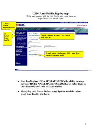
S A F E T Y & I NSTALL ATIONINF O R MAT I ONPower Cable and ConnectionSAFE T Y & INS TALL ATION IN FORMAT I ONAn IEC power connector is supplied with the Redbox, which has a moulded plug, attached– this is a legal requirement. If no moulded plug has been supplied with your Redbox, pleasecontact your supplier, because an IEC connector is always supplied from the Sonifex factory.If for any reason, you need to use the Redbox with a different power cable, you should usethe following wiring guidelines:Wire ColourGreen, or green and yellowBlue, or BlackBrown, or RedConnectionEarth (E)Neutral (N)Live (L)Fig B: Mains Cable Wire ColoursOrdering the Correct Mains LeadWhen ordering a Redbox from Sonifex, it is helpful if you can specify your requiredoperating voltage and mains lead. After the product code add:UK, for 230V, UK 3 pin to IEC leadEC, for 230V, European Schuko 2 pin to IEC leadUS, for 115V, 3 pin to IEC leadAU for 230V, Australasian 3 pin to IEC leadFig C: Mains Lead Table.E.g. order RB-BL2 UK for a UK IEC lead to be supplied.Installation InformationAtmosphereThe units should be installed in an area that is not subject to excessive temperaturevariation ( 0 C, 50 C), moisture, dust or vibration.Electromagnetic RadiationThe cover is connected to earth by means of the fixing screws. It is essential to maintainthis earth ground connection to ensure a safe operating environment and provideelectromagnetic shielding.Fitting RedboxesRedboxes can be fixed to the underside of a mixing desk, or other surfaces using 4.2mmholes in the sides and fixed with 2 x M4 screws or 2 x No. 6 countersink wood screws.ivRedbox User Handbook No 2
SAFE T Y & INSTALL ATIONIN FORMATIONThey can also be rack-mounted, with either the front, or rear of the Redbox positioned at thefront of the rack:Front Mounting Redboxes: For rack mounting smaller (28cm) units the optional RB-RK1(Red) or RB-RK1B (Black) kit can be used (which include 4 off M6 panel fixing screws).Fig D: RB-RK1Small Redbox Front Rack-mount Kit .Rear Mounting Redboxes: For rear panel mounting you can use either the RB-RK2, orRB-RK3, depending on the size of your Redbox.RB-RK2 1U rear panel rack kit for small Redbox range, e.g., RB-BL2Fig E: RB-RK2 Small Redbox Rear Rack-mount Kit.e.g. for fitting an RB-BL2:Wherever you see this symbol an RB-RK2 small Redbox rear panel 19” rack kit can be used :RB-RK3 1U rear panel rack kit for large Redbox range, e.g., RB-DA6Fig F: RB-RK3 Large Redbox Rear Rack-mount Kit.S A FE T Y & I N STALL ATION INFO RMATIO NWherever you see this symbol an RB-RK1 front panel rack kit can be used :e.g. for fitting an RB-DA6:Wherever you see this symbol an RB-RK3 large Redbox rear panel 19” rack kit can be used :Note: When fitting the rear-mounting rack-kits, a notch has beenleft on the inside of the right-hand rack-piece for the mains cable topass through. Make sure that the mains cable has been put throughthe notch before attaching the right hand rack-piece.Redbox User Handbook No 2v
S A F E T Y & I NSTALL ATIONINF O R MAT I ONWEEE & RoHS Directives - Sonifex StatementSAFE T Y & INS TALL ATION IN FORMAT I ONThe Waste Electrical and Electronic Equipment (WEEE) Directive was agreed on13 February 2003, along with the related Directive 2002/95/EC on Restrictionsof the use of certain Hazardous Substances in electrical and electronicequipment (RoHS).The Waste Electrical and Electronic Equipment Directive (WEEE) aims to minimise theimpacts of electrical and electronic equipment on the environment during their life timesand when they become waste. It applies to a huge spectrum of products. It encouragesand sets criteria for the collection, treatment, recycling and recovery of waste electrical andelectronic equipment. All products manufactured by Sonifex Ltd have the WEEE directivelabel placed on the case. It gives a contact for individuals who are unsure about the correctprocedure when the product has reached its “end of use”.Sonifex Ltd will be happy to give you information about local organisations that canreprocess the products, or alternatively all products that have reached “end of use” can bereturned to Sonifex and will be reprocessed correctly free of charge.Sonifex Ltd has phased out the use of certain hazardous substances identified in theEuropean Union’s Restriction of Hazardous Substances (RoHS) directive. The RoHS directivelimits the use of certain hazardous substances currently used in EEE manufacture, includinglead, mercury, cadmium, hexavalent chromium, and halide-containing compounds PBB(polybrominated biphenyl) and PBDE (polybrominated diphenyl ether). Elimination of thesesubstances will result in more environmentally friendly recycling of electronic equipment.For the products which Sonifex manufacture, the main area where products were affectedwas in the use of lead for manufacturing and assembling electronics circuit boards.Sonifex Ltd practices lead-free (LF) manufacturing processes. LF solder is used on thesurface-mount PCB manufacturing processes and for hand soldering. The printed circuitboards (PCBs) used are either gold plated, or immersion tin plated, both of which use nolead. Historically the PCBs were hot air solder levelled (HASL) PCBs which used tin/leadbased solder.The manufacturing processes include the assembly of purchased components from varioussources. Product is offered as RoHS compliant, or LF, only after sufficient evidence is receivedfrom the component manufacturers that their components are RoHS compliant. SonifexLtd relies solely on the distributor, or manufacturer, of the components for identification ofRoHS compliance. Thus whilst every effort is made to ensure compliance, Sonifex Ltd makesno warranty, or certification, or declaration of compliance concerning said components.Sonifex Ltd defines “Lead Free” as pertaining to any product, which has been manufacturedby Sonifex Ltd using components which have been declared by the manufacturers as“Lead Free”. All statements by Sonifex Ltd of RoHS compliance are based on componentmanufacturer documentation.viRedbox User Handbook No 2
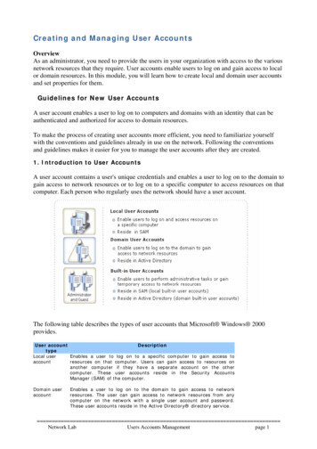
MATC HING CON VERTERS11 RB-UL1 Single, RB-UL2 Dual & RB-UL4 Quad Stereo UnbalancedTo Balanced ConvertersIntroductionFig 1-2: RB-UL4 Front Panel.The RB-UL1 single, RB-UL2 dual & RB-UL4 quad stereo units are used for interfacingdomestic, or semi-pro unbalanced equipment to professional balanced line levels.All connections are on the rear panel. The RCA unbalanced inputs have an impedance of10kΩ bridging and are routed to the balanced XLR-3 outputs with an output impedanceof 50Ω.The RB-UL1 has two inputs & outputs, the RB-UL2 has four inputs & outputs and the RB-UL4has eight inputs & outputs.The output gain can be individually adjusted for left and right channels by using pre-setpotentiometers accessible through the rear panel. A LED power indicator on the front paneldisplays the power supply connection.System Block DiagramLeft InputConsumer/UnbalancedRight InputConsumer/UnbalancedPhonoGainPhonoGainLeft OutputProfessional/BalancedRight OutputProfessional/BalancedMATCH I N G CON VERTERS - RB -UL1, R B - UL2, RB -UL4Fig 1-1: RB-UL1 & RB-UL2 Front Panel.Fig 1-3: Block Diagram For a Single Channel (x2 for RB-UL2, x4 for RB-UL4).Redbox User Handbook No 21
1MATC H I N G CO NVE R T E R SRear Panel Connections and OperationMATC HIN G CO NVER TE RS - RB - UL1, RB - U L2 , RB - U L4RCAPhonoInputsOutputLevelAdjustmentFig 1-4: RB-UL1 Rear Panel.RCAPhonoInputsOutputLevelAdjustmentStereo BalancedOutputsFig 1-5: RB-UL2 Rear Panel.RCAPhonoInputsFig 1-6: RB-UL4 Rear Panel.2StereoOutputsOutputLevelAdjustmentStereo BalancedOutputsRedbox User Handbook No 2
MATC HING CON VERTERS1RCA Phono Inputs (Left and Right)The stereo left and right RCA inputs are unbalanced and have an impedance of 10kΩ. Theyare routed to the stereo balanced XLR 3 pin output connectors.Outputs (Left and Right)The XLR 3 pin output plug connectors are electronically balanced with an outputimpedance of 50Ω. They have the following connections:Pin 1: ScreenPin 2: PhasePin 3: Non-phaseRedbox User Handbook No 2MATCH I N G CON VERTERS - RB -UL1, R B - UL2, RB -UL4Output Level AdjustmentThe output gain can be individually adjusted for left and right channels throughpre-set potentiometers which are accessible through the rear panel. The gain rangeof the unbalanced to balanced converter is -15dBu to 15dBu ref -15dBu into theunbalanced input.3
1MATC H I N G CO NVE R T E R SMATCH ING CON VERT ER S - RB - UL1, RB - U L2 , RB - U L4Technical SpecificationsAudio SpecificationsMaximum Input Level:Input Impedance:Output Impedance:Maximum Output Level:Distortion:Noise:Common Mode Rejection:Frequency Response:Gain Range: 28dBu 10kΩ 50Ω 28dBu0.01% THD @ 1kHz ref 8dB output-100dB unity gain, ref 8dB output 66dB typically20Hz to 20kHz 0.1dB (600Ω load, ref 1kHz)Balanced output: -15dBu to 15dBu, ref -15dBu intounbalanced RCA inputConnectionsInputs:Outputs:Mains Input:Fuse Rating:2, 4 (RB-UL2) or 8 (RB-UL4) x RCA phono (unbalanced)2, 4 (RB-UL2) or 8 (RB-UL4) x XLR 3 pin male (balanced)Filtered IEC, 110V-120V, or 220-240V switchable, fused,6W maximumAnti-surge fuse 100mA 20 x 5mm (230VAC)Anti-surge fuse 250mA 20 x 5mm (115VAC)Equipment TypeRB-UL1:Single stereo unbalanced to balanced converterRB-UL2:Dual stereo unbalanced to balanced converterRB-UL4:Physical SpecificationsRB-UL1 & RB-UL2:Dimensions (Raw):Dimensions (Boxed):Weight RB-UL1:Weight RB-UL2:RB-UL4:Dimensions (Raw):Dimensions (Boxed):Weight:4Quad stereo unbalanced to balanced converter28cm (W) x 10.8cm (D) x 4.2cm (H) (1U)11” (W) x 4.3” (D) x 1.7” (H) (1U)36cm (W) x 20.5cm (D) x 6cm (H)14.2” (W) x 8” (D) x 2.4” (H)Nett: 1.00kg Gross: 1.45kgNett: 2.2lbsGross: 3.2lbsNett: 1.05kg Gross: 1.5kgNett: 2.3lbsGross: 3.3lbs48cm (W) x 10.8cm (D) x 4.2cm (H) (1U)19” (W) x 4.3” (D) x 1.7” (H) (1U)53cm (W) x 20.5cm (D) x 6cm (H)21” (W) x 8” (D) x 2.4” (H)Nett: 1.3kgGross: 1.9kgNett: 2.9lbsGross: 4.2lbsRedbox User Handbook No 2
MATC HING CON VERTERS22 RB-LU4 Quad Stereo Balanced To Unbalanced ConverterIntroductionFig 2-1: RB-LU4 Front Panel.All connections are on the rear panel. The eight XLR-3 electronically balanced inputs have animpedance of 20kΩ bridging and are routed to eight unbalanced RCA phono outputs withan output impedance of 50Ω.The output gain can be individually adjusted for left and right channels by using pre-setpotentiometers accessible through the rear panel. An LED power indicator is situated on thefront panel, which displays the power supply connection.Redbox User Handbook No 2MATCH I N G CON VERTERS - RB -LU4The RB-LU4 is a quad stereo unit for interfacing professional balanced equipment todomestic, or semi-pro unbalanced line levels.5
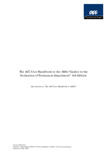
2MATC H I N G CO NVE R T E R SSystem Block DiagramLeft Input 1Professional/BalancedMATCHING CON VERTE RS - RB - LU 4Right Input 1Professional/BalancedLeft Input 2Professional/BalancedRight Input 2Professional/BalancedLeft Input 3Professional/BalancedRight Input 3Professional/BalancedLeft Input 4Professional/BalancedRight Input 4Professional/BalancedPhonoLeft Output 1Consumer/UnbalancedGainPhonoRight Output 1Consumer/UnbalancedGainPhonoLeft Output 2Consumer/UnbalancedGainPhonoRight Output 2Consumer/UnbalancedGainPhonoLeft Output 3Consumer/UnbalancedGainPhonoRight Output 3Consumer/UnbalancedGainPhonoLeft Output 4Consumer/UnbalancedGainPhonoRight Output 4Consumer/UnbalancedGainFig 2-2: RB-LU4 Block Diagram.6Redbox User Handbook No 2
MATC HING CON VERTERSRear Panel Connections and OperationFig 2-3: RB-LU4 Rear Panel.RCAPhonoOutputsOutputLevelAdjustmentInputs 1-4 (Left and Right)The XLR 3 pin sockets used for the left and right channel inputs of Input 1 are electronicallybalanced and have an impedance of 20kΩ bridging. They are routed to an unbalancedRCA (phono) output with an output impedance of 50Ω. Each XLR has the followingconnections:Pin 1: ScreenPin 2: PhasePin 3: Non-phaseRCA Phono Outputs 1-4 (Left and Right)These RCA (phono) outputs are unbalanced and have an output impedance of 50Ω.Output Level AdjustmentThe output gain can be individually adjusted for left and right channels through pre-setpotentiometers which are accessible through the rear panel. The gain of the balanced tounbalanced converter is variable within a range of -28dBu to 15dBu ref. -15dBu into thebalanced input.Redbox User Handbook No 2MATCH I N G CON VERTERS - RB -LU4Stereo BalancedInputs27
2MATC H I N G CO NVE R T E R SMATCHING CON VERTE RS - RB - LU 4Technical Specifications8Audio SpecificationsMaximum Input Level:Input Impedance (XLR):Output Impedance (RCA) :Maximum Output Level:Distortion:Noise:Common Mode Rejection:Frequency Response:Gain Range:ConnectionsInputs:Outputs:Mains Input:Fuse Rating:Equipment TypeRB-LU4:Physical SpecificationsDimensions (Raw):Dimensions (Boxed):Weight: 28dBu 20kΩ balanced bridging 50Ω 22dBu0.01% THD @ 1kHz, ref 8dBu output-100dB, unity gain, ref 8dBu output 66dB typically20Hz to 20kHz 0.1dB (600Ω load, ref 1kHz)Unbalanced Output: -28dBu to 15dBu, ref -15dBu intobalanced XLR input8 x XLR 3 pin female (Balanced)8 x RCA phono (Unbalanced)Filtered IEC, 110V-120V, or 220-240V switchable, fused,6W maximumAnti-surge fuse 100mA 20 x 5mm (230VAC)Anti-surge fuse 250mA 20 x 5mm (115VAC)Quad stereo balanced to unbalanced co
Redbox User Handbook No 2 g FIGURES FIGURES Figures Fig A: Packing List. ii Fig B: Mains Cable Wire Colours iv Fig C: Mains Lead Table. iv Fig D: RB-RK1Small Redbox Front Rack-mount Kit . v Fig E: RB-RK2 Small Redbox Rear Rack-mount Kit. v Fig F: RB-RK3 Large Redbox Rear Rack-mount Kit. v Fig 1-1: RB-UL1 & RB-UL2 Front Panel. 1 Fig 1-2: RB-UL4 .