Transcription
The Mobile User Objective SystemJohn D. Oetting and Tao Jenhe Navy has used the military UHF band (300–400 MHz) for satellitecommunications (SATCOM) since the launch of the first Fleet Satellite Communications (FLTSATCOM) satellite in 1978. In the past 30 years, severalreplacement constellations have been launched, and UHF satellites have become jointassets used by all the services; however, the communication waveforms and architectures have not changed significantly. This article describes a radically new UHF SATCOMsystem called the Mobile User Objective System (MUOS). MUOS, which is based onthe same technology now being widely deployed on terrestrial cellular phone systems,will revolutionize the way that the DoD uses UHF SATCOM. This article describes theMUOS system architecture, APL’s role in the MUOS program, and the impact of ourwork on other programs at APL.INTRODUCTIONThe Mobile User Objective System (MUOS) is theDoD’s next-generation UHF satellite communications(SATCOM) system. When fully deployed, MUOSwill consist of a constellation of four geosynchronoussatellites (plus an on-orbit spare) and the associatedground stations. The MUOS system1 will provideglobal connectivity between MUOS users and will alsoprovide MUOS users access to the Defense InformationSystems Agency’s (DISA) terrestrial voice and InternetProtocol (IP) networks. Point-to-point, broadcast, andnetted (push-to-transmit) services will be supported atdata rates ranging from 2.4 Kbps up to 384 Kbps. TheJOHNS HOPKINS APL TECHNICAL DIGEST, VOLUME 30, NUMBER 2 (2011)MUOS waveform—Spectrally Adaptive WidebandCode Division Multiple Access (SA-WCDMA)—isbased on cellular Third Generation Partnership Project(3GPP) technology. Design features include Rakereceivers, advanced turbo coding, and state-of-theart interference-mitigation techniques for maximumefficiency on both the UHF uplink and downlink.The first three satellites are currently being assembled,integrated, and tested, and the first launch is scheduledfor February 2012. One of the four ground stations iscompleted, and the other three ground stations areunder construction.103
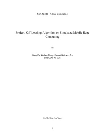
J. D. OETTINGANDT. JENIn addition to providing cellular-like service usingWCDMA technology, each MUOS satellite includesa legacy payload (the term legacy or legacy UHFSATCOM refers to the existing DoD UHF SATCOMcapability, which is based on frequency division multipleaccess and dedicated narrowband channels), which willprovide bent-pipe communication capabilities essentially identical to those of the UHF payload of a UHFfollow-on (UFO) satellite, the space element for theexisting legacy constellation. Because most of the UFOsatellites are operating well beyond their expected lifetimes, it is likely that the legacy capacity will declineduring the next few years. The launch of the MUOSsatellites will help to fill any potential gaps in legacyUHF SATCOM capacity, as well as provide the manynew capabilities of the WCDMA system, including morethan an order of magnitude increase in the worldwidecommunication capacity.MUOS ARCHITECTUREFigure 1 illustrates the MUOS architecture. Theheart of the MUOS system consists of the four active satellites in geosynchronous orbit and the four radio accessfacilities (RAFs) on the ground. Each satellite is in viewof two RAFs, and each RAF has two satellites in view.MUOS terminals communicate with the satellite viaUHF uplinks and downlinks. The satellite converts eachUHF uplink to digital format and sends the digitizedsignals to a RAF via a Ka-band feeder downlink. Thecombination of the UHF uplink, the satellite, and theKa-band downlink is called the user-to-base (U2B) path,in accordance with 3GPP terrestrial terminology. (Interms of the more familiar terrestrial cellular networksthat we use every day, each MUOS satellite correspondsto a cell tower, and each RAF corresponds to a base station. However, the “cell towers” are 23,000 miles highand the “cells” are more than 600 miles in diameter.)The RAFs demodulate and decode all of the user traffic they receive from the satellite. All RAFs are interconnected via high-capacity fiber optic terrestrial links,shown in Fig. 1 as thick orange lines. This terrestrialconnectivity allows RAFs to send data to the nearest switching facility. The switching facilities route thedata to either the Defense Information Systems Network(DISN) or to an appropriate MUOS RAF (one that is inview of a satellite that has the destination user withinits UHF footprint). Each RAF takes all of the data itreceives from the two switching facilities and uplinksapproximately half of the data to each of the two satellites in view via analog Ka-band feeder links. Each spacecraft amplifies the signals received from its two RAFs,downconverts them to the UHF band, and transmitsthem to MUOS terminals via the UHF downlink. TheFigure 1. MUOS system architecture. CONUS, continental United States.104JOHNS HOPKINS APL TECHNICAL DIGEST, VOLUME 30, NUMBER 2 (2011)
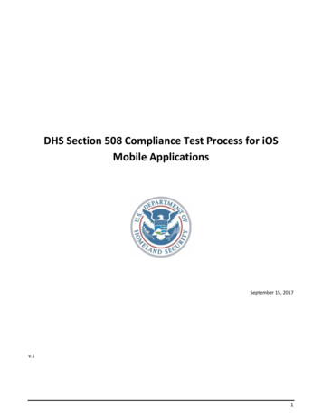
THE MOBILE USER OBJECTIVE SYSTEMcombination of the Ka-band uplink, the satellite, and theUHF downlink constitutes the base-to-user (B2U) path.Also shown in Fig. 1 are the network managementfacility (NMF) and the primary and secondary satellitecontrol facilities (SCFs). The NMF provides a management system for communications planning, allocating,and prioritizing access to the MUOS communicationresources. It provides the MUOS system with the information needed to perform priority-based, real-timecommunication resource allocation, as well as reallocation of resources and preemption of low-priority traffic, when absolutely necessary. The NMF also providesthe tools necessary to manage the MUOS network andprovide situational awareness. The SCFs receive statusinformation from the satellites (via the RAFs) and sendcommands to the satellites via the RAFs using securetelemetry links. Operators at the SCFs configure the satellite and ensure that it stays in the proper orbital location (stationkeeping).The flow of MUOS signals from user to base andbase to user is illustrated in Fig. 2, which also showsthe frequencies used for the UHF and Ka-band uplinksand downlinks. Each MUOS satellite uses a multibeamantenna (MBA) with a 14-m reflector for both transmission and reception of the MUOS UHF WCDMA signals.Legacy UHF signals are received by the satellite’s MBAbut are transmitted on the UHF downlink via a separatelegacy transmit antenna, which has a 5.4-m reflector.Both the MBA and the legacy transmit antenna reflectors are constructed of gold-plated mesh so that theycan be stored in a small volume and then deployed afterthe satellite is in orbit. The MBA forms 16 beams thatcover the entire footprint of the satellite, enabling muchhigher antenna gains than the Earth coverage antennasused by the UFO system. The additional antenna gainmakes it possible to provide connectivity to handheldterminals (although the MUOS satellites are designedto support handheld terminals, there are currently nohandheld terminals under development) and also greatlyreduces the required transmit power for all terminals.Note in Fig. 2 that 20 MHz of bandwidth is allocatedfor both the UHF uplink (300–320 MHz) and downlink(360–380 MHz). The uplink and downlink bandwidthis divided into four 5-MHz WCDMA channels. Eachuser within a given 5-MHz channel is assigned a different spreading code, enabling up to 500 users to sharea single channel, depending on the mix of data ratesand terminal types. The MBA enables all four channelsto be reused on each of the 16 beams, resulting in 64WCDMA channels per satellite (16 beams 4 channels per beam 64 channels). On the U2B path, each ofthe 64 channels is downlinked via the digital Ka-bandfeeder downlinks to a RAF, with 32 channels sent toeach of the two RAFs in view. On the B2U path, eachFigure 2. MUOS signal flow.JOHNS HOPKINS APL TECHNICAL DIGEST, VOLUME 30, NUMBER 2 (2011)105
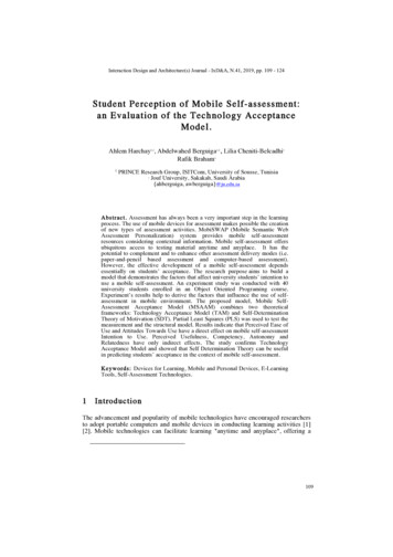
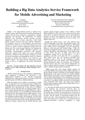
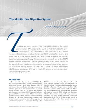
J. D. OETTINGANDT. JENRAF sends 32 channels via the analog Ka-band feederuplinks to each of the two satellites in view. The satellite switches each of the 64 channels it receives (32 fromeach RAF) to the appropriate downlink beam and channel. Each of the 64 channels per satellite is referred to asa satellite beam carrier (SBC). Within the constraintsimposed by system loading, the ground facilities attemptto spread the load as uniformly as possible among all ofthe available SBCs in order to maximize system capacity.Figure 3 shows the worldwide coverage provided bythe four active MUOS satellites (latitude 65 north tolatitude 65 south). The figure also shows the coverageprovided by individual MUOS beams, as well as theportion of the Earth’s surface covered by two satellites(dual coverage). More than 70% of the required coverage area is covered by two satellites. Coverage by twosatellites provides more capacity to a region as well as theability to communicate when one satellite is disabled,obstructed, or jammed.The MUOS UHF frequency plan is illustrated inFig. 4, which also shows the legacy frequencies fallinginto the MUOS UHF uplink 5-MHz channels. The factthat the UHF band is heavily populated with externalinterferers (external interferers encompass a wide rangeof signals found in the heavily congested UHF bandsused by MUOS, including line-of-sight communicationsignals, radar signals, radio navigation signals, and commercial television) as well as our own legacy SATCOMsignals necessitated the use of a modulation techniquethat can coexist with many other users sharing the samebandwidth. The use of power control and spread-spec-trum WCDMA enables MUOS to share the band withlegacy users without significant performance degradation to the legacy users or to the MUOS WCDMA users.Adaptive signal processing is used to notch out interferers on both the U2B and the B2U paths. Legacy users andexternal interferers within the 5-MHz WCDMA uplinkchannels are notched out by processing performed atthe RAF. External interferers on the UHF downlink aremitigated through adaptive filtering performed by theMUOS terminals. MUOS terminals can also implementnotches in the MUOS WCDMA transmitted signals inorder to comply with host nation agreements or to avoidinterfering with other nearby communication assets. Upto several hundred kilohertz of each 5-MHz channel canbe notched out before significant performance degradation can be measured. Furthermore, the MUOS powercontrol loops automatically increase the transmittedpower to compensate for any loss that does occur (seediscussion of power control below).MUOS implements closed-loop power control independently on both the U2B and B2U paths so that eachterminal transmits just enough power to close its UHFuplink and the satellite transmits just enough power toclose all of its UHF downlinks. 3GPP WCDMA-basedcell phones have very similar power control loops;however, power control for MUOS is more challenging because of the 640-ms round-trip propagation delaybetween the terminals and the RAF. Like terrestrialWCDMA systems, MUOS uses two power control loops:an inner loop which attempts to track channel gain variations in order to achieve a target Eb/N0 (the energy perFigure 3. MUOS global coverage. The MUOS terminals within the gray shaded areas are in view of two MUOS satellites. CMTW, combined major theaters of war.106JOHNS HOPKINS APL TECHNICAL DIGEST, VOLUME 30, NUMBER 2 (2011)
THE MOBILE USER OBJECTIVE SYSTEMLegacy UHF uplink292 MHz2 311–1213–1456 27–3917–1815–16Legacy UHF downlink244 MHz19–26427–39 2 3 4 5 611–1213–14318 MHz7 8 9 1019–26Four 5-MHz WCDMA channels300 MHz270 MHzMUOS UHF uplinkFour 5-MHz WCDMA channels7 8 9 1017–1815–16360 MHz380 MHzMUOS UHF downlinkMUOS UHFuplinkLegacy UHFdownlinkMHz250244260MUOS UHFdownlinkLegacy UHFuplink270320 MHz280300292310320330340350360370380MHz318Figure 4. MUOS UHF frequency plan. MUOS uplink carriers are dynamically notched as necessary to comply with host nation agreements. Colors indicate four legacy frequency plans, and dashed boxes indicate frequency bands allocated for future MUOS use.bit to noise power spectral density ratio) and an outerloop which monitors communications performance andmakes adjustments to the target Eb/N0. To deal with thelong delays, MUOS uses two key techniques not foundin terrestrial systems. First, the inner loop uses linearprediction to predict, on the basis of the current and pastfade values, the fade state of the channel 640 ms in thefuture. Second, whereas terrestrial systems rely on cyclicredundancy check failures to estimate performance (sothat the outer loop can make appropriate adjustments tothe target Eb/N0), the MUOS outer loop estimates theinstantaneous block error rate by applying a polynomialfit to sequences of signal-to-interference ratio measurements made on each 10-ms frame. Details of these algorithms can be found in Ref. 2.Another MUOS power control challenge relates tothe DoD-unique netted capability, whereby one user’stransmission is sent to all other members of a net.Members of the net can be in the same beam, differentbeams of the same satellite, or different satellite beams.Because only one netted user transmits at a time, U2Bpower control for nets works identically to power controlfor point-to-point connections. However, on the B2Upath, the satellite must provide enough power to eachSBC containing net members to ensure that the mostdisadvantaged terminal is able to achieve the requiredquality of service. This goal is achieved in the following manner. If nothing is heard from any user terminalin a given SBC, the ground station reduces the powerJOHNS HOPKINS APL TECHNICAL DIGEST, VOLUME 30, NUMBER 2 (2011)for each user in the SBC by a specified increment atthe beginning of each power control interval. Meanwhile, each user on the net is continuously monitoringits downlink signal-to-interference ratio. When a userdetermines that the next power control decrement willreduce its signal-to-interference ratio below a designated threshold, it sends a message to the ground facilityasking either for no decrease or, if needed, an increase inpower for the next power control interval. In this way,all users are allocated the satellite power they need tomaintain their required level of performance.In addition to spread spectrum modulation, MUOSuses state-of-the-art error correction coding with turbodecoding to reduce the required power and increaserobustness. Rake receivers (a Rake receiver combatsmultipath fading by coherently combining the energyreceived on each path) are used at both the RAFs andin the user terminals to combat the effects of fadingchannels. Extensive simulations and hardware testshave demonstrated that the Rake receivers used onMUOS provide excellent performance over a wide variety of UHF SATCOM channels. The MUOS waveformalso incorporates extensive interleaving, including theoption of uplink interleaving over intervals as longas 640 ms. The MUOS network features an IP-basedcore. All data are Type 1 encrypted within the terminal either by a High Assurance IP Encryptor (HAIPE)or by a Secure Communication Interoperability Protocol (SCIP) device. SCIP is used for all transmissions107
J. D. OETTINGANDT. JENbetween MUOS users and the Defense Switched Network (DSN), the DoD’s terrestrial voice network.APL’S ROLE IN THE MUOS PROGRAMAPL has been involved in the MUOS program formore than 10 years, beginning with our developmentof the analysis of alternatives, which was finalizedin 2001. APL provided significant technical expertisein analyzing the performance of 18 different candidatearchitectures and defining the government referencearchitecture. We led the development of the measuresof effectiveness and measures of performance for thesystem. APL was instrumental in the development ofthe MUOS performance specification and the requestfor proposals. We led the performance assessments forMUOS source selection and provided technical directions on system capacity, link availability, and qualityof service requirements—the most important performance parameters for the system. We developed concepts and negotiated requirements for supporting DoDIP-centric requirements that were essential for MUOSto gain approval of its key decision point B acquisitionmilestone.In addition, APL provided technical directions thathelped MUOS successfully complete the system preliminary design review and the system critical design review.We developed an in-depth technical road map thatguided the application of IP networking technologies inthe MUOS architecture and design. We developed aninformation assurance solution that helped the MUOSprogram gain approval to use modified commercial-offthe-shelf equipment to provide assured communications.We guided major architecture and design decisionsincluding the adoption of an all-IP core network designand the connections into DSN, Unclassified-but-Sensitive IP Router Network (NIPRNET), and Secret IPRouter Network (SIPRNET).We are currently providing technical support in theareas of system performance analysis, test and evaluation of the ground hardware and software, networkmanagement, information assurance, and key management. APL also approves all changes to the satellite specification that affect satellite RF performance.Although the critical design review was held in March2007, there have been a number of significant changesto the MUOS design since then. APL has been heavily involved in determining the impact of these designchanges on system performance. Some specific examples of APL’s contributions to the MUOS program aredescribed some detail in the following subsections.MUOS Performance ModelBecause of a number of factors, assessing the capacity of a WCDMA system is an extremely challenging108problem. The fact that quality of service is limited by theinterference from other users sharing the same 5-MHzchannels (multiple access interference), rather than bythermal noise, and the fact that the power levels of everyuser are constantly being adjusted by the power controlloops make it impossible to assess the performance usingthe conventional link budget approach. Therefore, it wasnecessary to assess system capacity by means of simulation. For this purpose, we use a tool called the MUOSPerformance Model (MPM). Rather than attempting tosimulate the dynamic behavior of 20,000 users, we generate a snapshot of the MUOS system that consists of allusers that are transmitting and receiving MUOS data ata particular instant of time. For each link in the snapshot, MPM calculates a link budget every 10 ms, takinginto account inverse-square propagation loss, fading,interference, multiple access interference, and manyother factors. For every user, MPM also implements theactual power control algorithms used by the MUOSsystem. The primary outputs from an MPM run are theaverage link availability for every user, the transmittedpower versus time for each of the four satellites, and theuplink load factor (a measure of traffic loading) versustime for each of the four satellites.MPM was developed over the course of many yearsby an integrated team consisting of contractors and government/APL personnel. APL has developed a numberof algorithms used by MPM, some of which will bedescribed in this section. APL’s most important contribution to MPM is our suggestion of averaging linkavailability results over multiple MPM runs. The mostimportant output of MPM is the average annual linkavailability for each of the thousands of users includedin a simulation run. According to a long-standing agreement between the government and the MUOS contractors, if even one of these users has a link availability lessthan the required 97% link availability, the system doesnot meet its capacity requirement, which is the mostimportant performance requirement for the MUOS program. Prior to March 2009, link availability was computed on the basis of a single MPM run, which consistsof 24 segments spaced 1 h apart, with each segment covering 200 s of real time. Most of the random variablesassociated with the simulation are changed for each segment, but the location of each user is kept fixed for all24 segments.APL recognized two significant problems with thisapproach. First, the fact that there are only 24 draws foreach random variable means that one or two bad drawsfor one user can potentially result in that user failingto meet the 97% link availability requirement. Second,the fact that the users stay in fixed locations over thecourse of the simulation run means that a user locatedin an unfavorable position (e.g., on the edge of a beamor in between multiple beams) can fail to meet linkJOHNS HOPKINS APL TECHNICAL DIGEST, VOLUME 30, NUMBER 2 (2011)
THE MOBILE USER OBJECTIVE SYSTEMavailability. To alleviate these problems, APL suggestedperforming approximately 10 runs for the same usersand averaging the link availability of each user over all10 runs (eventually, an agreement was reached to use12 runs, and this is the number of runs performed tothe present day). Users would be randomly repositionedwithin their area of operations at the beginning of eachrun. After this method was introduced in March 2009,the predicted worldwide throughput increased (literallyovernight) from less than 100% of the required throughput to greater than 120% of the required throughput.This increase in the estimated capacity occurred becauseof the drastic reduction in the variance of the link availability estimates produced by the averaging procedure.APL also developed the MPM model for Ka-bandreradiated noise. The MUOS B2U path includes ananalog Ka-band uplink and a UHF downlink, whichis essentially a standard bent-pipe satellite link. TheMUOS satellite simply translates each channel from theKa-band to the appropriate UHF frequency, routs thechannel to the appropriate beam carrier, and amplifieseach beam carrier prior to transmission to the MUOSusers via the UHF downlink. As a result, any noise onthe Ka-band uplink will be amplified and retransmittedon the UHF downlink. MPM must model this additionalnoise, which is most severe when the Ka-band uplink isin a deep fade. Furthermore, the fading characteristicsdepend on the climate at the ground station and the elevation angle to the satellite and therefore differ for eachof the eight Ka-band uplinks (four RAFs, each with twosatellites in view) and vary with time (because of satellite motion). At the time that the MPM reradiated noisealgorithm was developed, we were conducting only one24-segment run (rather than 12), so a major concern wasthat a few bad draws for a particular Ka-band link couldcause link availability failures for every user traversingthat link.APL came up with a solution based on the fact thatthere are 192 random draws in each MPM run (8 linksand 24 draws per link). For each MPM run, the algorithmensures that two of the draws will be assigned a 96% fadedepth, two will be assigned a 97% fade depth, two willbe assigned a 98% fade depth, two will be assigned a99% fade depth, one will be assigned a 99.5% fade depth,and the rest will be assigned a 95% fade depth (at the95% fade depth, the reradiated noise has little impact, sothere is no need to granulize the fade depths below 95%).For each segment, each of the eight links is assigned apercentile fade depth based on the above distribution,and the fade depth corresponding to that percentile isfound in a precomputed look-up table. The look-up tableincludes fade depths for each of the above percentiles foreach link and for each of the 24 hours in a day. Oncethe fade depth is determined, the reradiated noise canbe computed in a straightforward manner.JOHNS HOPKINS APL TECHNICAL DIGEST, VOLUME 30, NUMBER 2 (2011)Another APL contribution to MPM was an algorithm for automatically generating snapshots having therequired throughput characteristics. Before we developed this algorithm, a snapshot was generated by goingthrough each of the MUOS point-to-point links andnets and including each link or net with a probabilityequal to its duty cycle. This method produced loading characteristics with significant variation from onerandom seed to the next. To obtain a valid snapshot,it was necessary for someone to manually examine thestatistics associated with a large number of snapshotsand pick the snapshot that seemed to provide the closest approximation to the specified average loading characteristics. This process was labor intensive and proneto errors.APL conceived of an alternative approach thatwould ensure that every snapshot generated by MPMwould have the desired throughput values for five mutually exclusive categories of traffic. To achieve this result,we allow the user to input the five target throughputvalues corresponding to the five traffic types. As before,we go through the links/nets one by one, selecting alink or net with a probability equal to its duty cycle.However, instead of going through the entire list exactlyonce, we continue until all five throughput targets aremet. Once a particular target is met, no more nets/linksin that category can be selected. In order to avoid biasing the selection probabilities, we randomize the orderof the links/nets prior to each iteration of the algorithm.APL developed and tested a MATLAB implementationof the algorithm and then wrote the design descriptionused by the software coder to implement the algorithmin MPM.Legacy InterferenceAPL has performed a significant amount of work pertaining to the effect of legacy interference on MUOScommunication performance. Note from Fig. 4 that theMUOS uplink frequency band (300–320 MHz) overlaps the uplink bandwidth used by the existing legacysatellites (292–318 MHz). Because the legacy satelliteshave greatly exceeded their design life and because eachMUOS satellite includes a legacy payload in addition tothe WCDMA payload, significant narrowband legacyinterference will be present within the MUOS bandwidth. Although the ground processors have the capability to eliminate most of this interference by means ofadaptive filtering, there have been long-standing concerns that the legacy signals, which greatly exceed thepower level of the WCDMA signals, could saturate thesatellite receiver front end or the analog-to-digital converters on the satellite.APL performed the analysis that was used to establishthe levels of legacy interference that the system must beable to withstand, and these levels were incorporated into109
J. D. OETTINGANDT. JENthe MUOS system specifications. Later, APL developeda simulation to evaluate the effects of legacy interference3 and was instrumental in planning and conducting legacy interference tests using the MUOS payloademulator.4 Specifically, APL convinced the governmentto spend the money to perform the tests, worked closelywith the contractors to formulate the test plan, developed the files used by the arbitrary waveform generatorto emulate the legacy interferers, witnessed the tests,and made significant contributions to the test report. Toensure that the first MUOS spacecraft has performancesimilar to that of the payload emulator, APL convincedthe government and the contractors to conduct similartests using the actual payload during end-to-end testingprior to launch.Modeling and SimulationIn addition to the legacy interference simulation,APL has developed simulations to estimate the systemacquisition time statistics for the worst-case MUOS user,analyze the peak-to-average power ratio statistics of theMUOS waveform,5 and analyze the dynamic loadingstatistics on the basis of the specified user duty cyclesand data rates. The dynamic traffic model was used toestimate the factor used to convert the average load tothe 99th percentile load, which is the agreed-upon loading factor for all MPM runs.APL is currently developing a simulation of theU2B path that will enable the government to evaluatepotential improvements to the MUOS system, including improvements in capacity and jam resistance. Todate, we have simulated the WCDMA transmitter, mostof the fading channel models, the interference excisionalgorithm, interleaving, and the turbo decoder. We havealso implemented and tested a channel estimation algorithm used to provide channel information to the Rakereceiver. Eventually, we will add satellite nonlinearities,beam combining, and various types of jammers to thesimulation. Using our simulation, we will be able to estimate the increase or decrease in required Eb/N0 resulting from the use of a new technique or the presence ofjammers. This information can be input into MPM inorder to evaluate the resulting gain or loss in systemcapacity. This capability will allow the government toevaluate potential improvements to MUOS. Because ofthe unique architecture of the MUOS system, it will bepossible to implement all of these improvements on theground without launching new satellites.Network ManagementAPL has been the lead systems engineer in the MUOSnetwork management area for many years. We oversawthe requirements, architecture, and design in many keyareas including communications planning, provisioning,110and IP address management. We successfully guided amajor engineering change proposal that made significant changes to over-the-air provisioning to simplify theprovisioning of MUOS terminals. We helped resolvetechnical issues in applying HAIPE dynamic discoverytechnologies. Currently, we are investigating ways toreduce the complexity of managing tens of thousands ofIP addresses, improve HAIPE dynamic discovery technologies, and streamline communications planning andprovisioning for tactical users.Requirements VerificationCurrently, APL is investing considerable effort inrequirements verification and analysis of test data. APLpersonnel are responsible for verification of 35 of the128 system-level requirements, including all requirements pertaining to communications quality of service. APL responsibilities include reviewing all testplans and procedures, witnessing key tests, analyzingtest data to en
The Mobile User Objective System John D. Oetting and Tao Jen he Navy has used the military UHF band (300-400 MHz) for satellite . interferers (external interferers encompass a wide range of signals found in the heavily congested UHF bands used by MUOS, including line-of-sight communication signals, radar signals, radio navigation signals .