Transcription
Chapter 18VHF and UHF Antenna SystemsAgood antenna system is one of the most valuable assets available to the VHF/UHF enthusiast.Compared to an antenna of lesser quality, an antenna that is well designed, is built of goodquality materials, and is well maintained, will increase transmitting range, enhance receptionof weak signals, and reduce interference problems. The work itself is by no means the least attractivepart of the job. Even with high gain antennas, experimentation is greatly simplified at VHF and UHFbecause the antennas are a physically manageable size. Setting up a home antenna range is within themeans of most amateurs, and much can be learned about the nature and adjustment of antennas. Nolarge investment in test equipment is necessary.The BasicsSelecting the best VHF or UHF antenna for a given installation involves much more than scanninggain figures and prices in a manufacturer’s catalog. There is no one “best” VHF or UHF antenna designfor all purposes. The first step in choosing an antenna is figuring out what you want it to do.GainAt VHF and UHF, it is possible to build Yagi antennas with very high gain—15 to 20 dB—on a physically manageable boom. Such antennas can be combined in arrays of two, four, six, eight, or more antennas.These arrays are attractive for EME, tropospheric scatter or other weak-signal communication modes.Radiation PatternsAntenna radiation can be made omnidirectional, bidirectional, practically unidirectional, or anything between these conditions. A VHF net operator may find an omnidirectional system almost anecessity, but it may be a poor choice otherwise. Noise pickup and other interference problems tend tobe greater with such omnidirectional antennas, and such antennas having some gain are especially badin these respects. Maximum gain and low radiation angle are usually prime interests of the weak signalDX aspirant. A clean pattern, with lowest possible pickup and radiation off the sides and back, may beimportant in high activity areas, or where the noise level is high.Frequency ResponseThe ability to work over an entire VHF band may be important in some types of work. ModernYagis can achieve performance over a remarkably wide frequency range, providing that the boom lengthis long enough and enough elements are used to populate the boom. Modern Yagi designs in fact arecompetitive with directly driven collinear arrays of similar size and complexity. The primary performance parameters of gain, front-to-rear ratio and SWR can be optimized over all the VHF or UHFamateur bands readily, with the exception of the full 6-meter band from 50.0 to 54.0 MHz, which is an8% wide bandwidth. A Yagi can be easily designed to cover any 2.0-MHz portion of the 6-meter bandwith superb performance.VHF and UHF Antenna Systems18-1
Height GainIn general, the higher the better in VHF and UHF antenna installations. If raising the antenna clearsits view over nearby obstructions, it may make dramatic improvements in coverage. Within reason,greater height is almost always worth its cost, but height gain (see Chapter 23) must be balanced againstincreased transmission-line loss. This loss can be considerable, and it increases with frequency. Thebest available line may not be very good if the run is long in terms of wavelengths. Line loss considerations (shown in table form in Chapter 24) are important in antenna planning.Physical SizeA given antenna design for 432 MHz has the same gain as the same design for 144 MHz, but beingonly one-third as large intercepts only one-ninth as much energy in receiving. In other words, theantenna has less pickup efficiency at 432 MHz. To be equal in communication effectiveness, the432-MHz array should be at least equal in size to the 144-MHz antenna, which requires roughly threetimes as many elements. With all the extra difficulties involved in using the higher frequencies effectively, it is best to keep antennas as large as possible for these bands.DESIGN FACTORSWith the objectives sorted out in a general way, decisions on specifics, such as polarization, type oftransmission line, matching methods and mechanical design must be made.PolarizationWhether to position antenna elements vertically or horizontally has been widely questioned sinceearly VHF pioneering. Tests have shown little evidence as to which polarization sense is most desirable. On long paths, there is no consistent advantage either way. Shorter paths tend to yield highersignal levels with horizontally polarized antennas over some kinds of terrain. Man-made noise, especially ignition interference, also tends to be lower with horizontal antennas. These factors make horizontal polarization somewhat more desirable for weak-signal communications. On the other hand, vertically polarized antennas are much simpler to use in omnidirectional systems and in mobile work.Vertical polarization was widely used in early VHF work, but horizontal polarization gained favorwhen directional arrays started to become widely used. The major trend to FM and repeaters, particularly in the 144-MHz band, has tipped the balance in favor of vertical antennas in mobile and repeateruse. Horizontal polarization predominates in other communication on 50 MHz and higher frequencies.Additional loss of 20 dB or more can be expected when cross-polarized antennas are used.TRANSMISSION LINESTransmission line principles are covered in detail in Chapter 24. Techniques that apply to VHF andUHF operation are dealt with in greater detail here. The principles of carrying RF from one location toanother via a feed line are the same for all radio frequencies. As at HF, RF is carried principally viaopen-wire lines and coaxial cables at VHF/UHF. Certain aspects of these lines characterize them asgood or bad for use above 50 MHz.Properly built open-wire line can operate with very low loss in VHF and UHF installations. A total line lossunder 2 dB per 100 feet at 432 MHz can easily be obtained. A line made of #12 wire, spaced 3/4 inch or morewith Teflon spreaders and run essentially straight from antenna to station, can be better than anything but themost expensive coax. Such line can be home-made or purchased at a fraction of the cost of coaxial cables, withcomparable loss characteristics. Careful attention must be paid to efficient impedance matching if the benefitsof this system are to be realized. A similar system for 144 MHz can easily provide a line loss under 1 dB.Small coax such as RG-58 or RG-59 should never be used in VHF work if the run is more than afew feet. Lines of 1 /2-inch diameter (RG-8 or RG-11) work fairly well at 50 MHz, and are acceptablefor 144-MHz runs of 50 feet or less. These lines are somewhat better if they employ foam instead ofordinary PE dielectric material. Aluminum-jacket “Hardline” coaxial cables with large inner conductors and foam insulation are well worth their cost, and can sometimes be obtained for free from local18-2Chapter 18
cable TV operators as “end runs”—pieces at the end of a roll. The most common CATV cable is1/2 -inch OD 75-Ω Hardline. Matched-line loss for this cable is about 1.0 dB/100 feet at 146 MHz and2.0 dB/100 feet at 432 MHz. Less commonly available from CATV companies is the 3/4 -inch 75-ΩHardline, sometimes with a black self-healing hard plastic covering. This line has 0.8 dB of loss per100 feet at 146 MHz, and 1.6 dB loss per 100 feet at 432 MHz. There will be small additional lossesfor either line if 75 to 50-Ω transformers are used at each end.Commercial connectors for Hardline are expensive but provide reliable connections with fullwaterproofing. Enterprising amateurs have “home-brewed” low-cost connectors. If they are properlywaterproofed, connectors and Hardline can last almost indefinitely. Hardline must not be bent toosharply, because it will kink.Beware of any “bargains” in coax for VHF or UHF use. Feed-line loss can be compensated to some extentby increasing transmitter power, but once lost, a weak signal can never be recovered in the receiver. Effects ofweather on transmission lines should not be ignored. Well constructed open-wire line works optimally innearly any weather, and it stands up well. Twin-lead is almost useless in heavy rain, wet snow or icing. The bestgrades of coax are completely impervious to weather; they can be run underground, fastened to metal towerswithout insulation, and bent into any convenient position with no adverse effects on performance.G-LineConventional two-conductor transmission lines and most coaxial cables are quite lossy in the upper UHF and microwave ranges. If the station and antenna are separated by more than 100 feet, common coaxial cables (such as RG-8) are almost useless for serious work. Unless the very best rigid coaxwith the proper fittings can be obtained, it is worthwhile to explore alternative methods of carrying RFenergy between the station and antenna.There is a single-conductor transmission line, invented by Georg Goubau (called “G-Line” in hishonor), that can be effectively used in this frequency range. Papers by the inventor appeared someyears ago, in which seemingly fantastic claims for line loss were made—under 1 dB per 100 feet in themicrowave region, for example. (See the Bibliography at the end of this chapter.) Especially attractivewas the statement that the matching device was broadband in nature, making it appear that a single GLine installation might be made to serve on, say, 432, 903 and 1296 MHz.The basic idea is that a single conductor can be an almost lossless transmission line at UHF, if asuitable “launching device” is used. A similar “launcher” is placed at the other end. Basically, thelauncher is a cone-shaped device that is a flared extension of the coaxial cable shield. In effect, thecone begins to carry the RF as the outer conductor is gradually “removed.” These launch cones shouldbe at least 3 λ long. The line should be large and heavily insulated, such as #14, vinyl covered.Propagation along a G-Line is similar to “ground wave,” or “surface wave” propagation overperfectly conducting earth. The dielectric material confines the energy to the vicinity of the wire,preventing radiation. The major drawback of G-Line is that it is very sensitive to deviation from straightlines. If any bends must be made, they should be in the form of a large radius arc. This is preferable toeven an obtuse angle change in the direction of the run. The line must be kept several inches away frommetal objects and should be supported with as few insulators as possible.WAVEGUIDESAbove 2 GHz, coaxial cable is a losing proposition for communication work. Fortunately, at this frequency the wavelength is short enough to allow practical, efficient energy transfer by an entirely differentmeans. A waveguide is a conducting tube through which energy is transmitted in the form of electromagnetic waves. The tube is not considered as carrying a current in the same sense that the wires of a twoconductor line do, but rather as a boundary that confines the waves in the enclosed space. Skin effectprevents any electromagnetic effects from being evident outside the guide. The energy is injected at oneend, either through capacitive or inductive coupling or by radiation, and is removed from the other end in alike manner. Waveguide merely confines the energy of the fields, which are propagated through it to thereceiving end by means of reflections against its inner walls.VHF and UHF Antenna Systems18-3
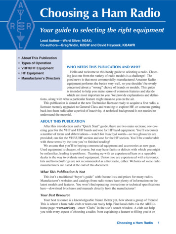
Analysis of waveguide operation is based onthe assumption that the guide material is a perfectconductor of electricity. Typical distributions ofelectric and magnetic fields in a rectangular guideare shown in Fig 1. The intensity of the electricfield is greatest (as indicated by closer spacing ofthe lines of force) at the center along the X dimension (Fig 1C), diminishing to zero at the endwalls. The fields must diminish in this manner, because the existence of any electric field parallel tothe walls at the surface would cause an infinitecurrent to flow in a perfect conductor. Waveguides,of course, cannot carry RF in this fashion.Fig 1—Field distribution in a rectangular waveguide. The TE10 mode of propagation is depicted.Table 1Waveguide DimensionsRectangularCutoff wavelength2XLongest wavelength transmitted with little attenuation 1.6XShortest wavelength beforenext mode becomes possible 1.1XCircular3.41r3.2r2.8rModes of PropagationFig 1 represents the most basic distribution ofthe electric and magnetic fields in a waveguide.There are an infinite number of ways in which thefields can arrange themselves in a waveguide (forfrequencies above the low cutoff frequency of theguide in use). Each of these field configurationsis called a mode.The modes may be separated into two generalgroups. One group, designated TM (transversemagnetic), has the magnetic field entirely transverse to the direction of propagation, but has acomponent of the electric field in that direction.The other type, designated TE (transverse electric)has the electric field entirely transverse, but has acomponent of magnetic field in the direction ofpropagation. TM waves are sometimes called Ewaves, and TE waves are sometimes called Hwaves, but the TM and TE designations are preferred.The mode of propagation is identified by thegroup letters followed by two subscript numerals.For example, TE10, TM11, etc. The number of possible modes increases with frequency for a givensize of guide, and there is only one possible mode(called the dominant mode) for the lowest frequency that can be transmitted. The dominantmode is the one generally used in amateur work.Waveguide DimensionsIn rectangular guide the critical dimension is X in Fig 1. This dimension must be more than 1/2 λ atthe lowest frequency to be transmitted. In practice, the Y dimension usually is made about equal to 1/2X to avoid the possibility of operation in other than the dominant mode.Cross-sectional shapes other than the rectangle can be used, the most important being the circularpipe. Much the same considerations apply as in the rectangular case.Wavelength dimensions for rectangular and circular guides are given in Table 1, where X is the width ofa rectangular guide and r is the radius of a circular guide. All figures apply to the dominant mode.18-4Chapter 18
Coupling to WaveguidesEnergy may be introduced into or extracted from a waveguide or resonator by means of either theelectric or magnetic field. The energy transfer frequently is through a coaxial line. Two methods forcoupling to coaxial line are shown in Fig 2. The probe shown at A is simply a short extension of theinner conductor of the coaxial line, oriented so that it is parallel to the electric lines of force. The loopshown at B is arranged so that it encloses some of the magnetic lines of force. The point at whichmaximum coupling is obtained depends on the mode of propagation in the guide or cavity. Coupling ismaximum when the coupling device is in the most intense field.Coupling can be varied by turning the probe or loop through a 90 angle. When the probe is perpendicular to the electric lines the coupling is minimum; similarly, when the plane of the loop is parallel to the magnetic lines the coupling is minimum.If a waveguide is left open at one end it will radiate energy. This radiation can be greatly enhancedby flaring the waveguide to form a pyramidal horn antenna. The horn acts as a transition between theconfines of the waveguide and free space. To effect the proper impedance transformation the horn mustbe at least 1/2 λ on a side. A horn of this dimension (cutoff) has a unidirectional radiation pattern with anull toward the waveguide transition. The gain at the cutoff frequency is 3 dB, increasing 6 dB witheach doubling of frequency. Horns are used extensively in microwave work, both as primary radiatorsand as feed elements for elaborate focusing systems. Details for constructing 10-GHz horn antennasare given later in this chapter.Evolution of a WaveguideSuppose an open wire line is used to carry RF energy from a generator to a load. If the line has anyappreciable length it must be mechanically supported. The line must be well insulated from the supports if high losses are to be avoided. Because high quality insulators are difficult to construct atmicrowave frequencies, the logical alternative is to support the transmission line with 1/4-λ stubs, shortedat the end opposite the feed line. The open end of such a stub presents an infinite impedance to thetransmission line, provided the shorted stub is nonreactive. However, the shorting link has a finitelength, and therefore some inductance. The effect of this inductance can be removed by making the RFcurrent flow on the surface of a plate rather than a thin wire. If the plate is large enough, it will preventthe magnetic lines of force from encircling the RF current.An infinite number of these 1/ 4-λ stubs may be connected in parallel without affecting the standingwaves of voltage and current. The transmission line may be supported from the top as well as thebottom, and when an infinite number of supports are added, they form the walls of a waveguide at itscutoff frequency. Fig 3 illustrates how a rectangular waveguide evolves from a two-wire parallel transmission line as described. This simplified analysis also shows why the cutoff dimension is 1 /2 λ.Fig 2—Coupling coaxial line towaveguide and resonators.Fig 3—At its cutoff frequency a rectangular waveguide can bethought of as a parallel two-conductor transmission line supported from top and bottom by an infinite number of 1 /4-λ stubs.VHF and UHF Antenna Systems18-5
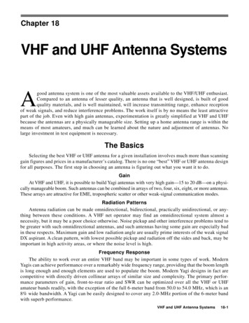
While the operation of waveguides is usually described in terms of fields, current does flow on theinside walls, just as on the conductors of a two-wire transmission line. At the waveguide cutoff frequency, the current is concentrated in the center of the walls, and disperses toward the floor and ceilingas the frequency increases.IMPEDANCE MATCHINGImpedance matching is covered in detail in Chapters 25 and 26, and the theory is the same forfrequencies above 50 MHz. Practical aspects are similar, but physical size can be a major factor in thechoice of methods. Only the matching devices used in practical construction examples later in thischapter are discussed in detail here. This should not rule out consideration of other methods, however,and a reading of relevant portions of both Chapters 25 and 26 is recommended.Fig 4—Matching methods commonly used at VHF.The universal stub, A, combines tuning andmatching. The adjustable short on the stub andthe points of connection of the transmission lineare adjusted for minimum reflected power on theline. In the delta match, B and C, the line isfanned out and connected to the dipole at thepoint of optimum impedance match. Impedancesneed not be known in A, B or C. The gammamatch, D, is for direct connection of coax. C1tunes out inductance in the arm. A folded dipoleof uniform conductor size, E, steps up antennaimpedance by a factor of four. Using a largerconductor in the unbroken portion of the foldeddipole, F, gives higher orders of impedancetransformation.18-6Chapter 18Universal StubAs its name implies, the double adjustmentstub of Fig 4A is useful for many matching purposes. The stub length is varied to resonate thesystem, and the transmission line attachment pointis varied until the transmission line and stub impedances are equal. In practice this involves moving both the sliding short and the point of lineconnection for zero reflected power, as indicatedon an SWR bridge connected in the line.The universal stub allows for tuning out anysmall reactance present in the driven part of thesystem. It permits matching the antenna to the linewithout knowledge of the actual impedances involved. The position of the short yielding the bestmatch gives some indication of the amount of reactance present. With little or no reactive component to be tuned out, the stub must be approximately 1/2 λ from load toward the short.The stub should be made of stiff bare wire orrod, spaced no more than 1/20 λ apart. Preferably itshould be mounted rigidly, on insulators. Once theposition of the short is determined, the center of theshort can be grounded, if desired, and the portion ofthe stub no longer needed can be removed.It is not necessary that the stub be connecteddirectly to the driven element. It can be made partof an open wire line, as a device to match coaxialcable to the line. The stub can be connected tothe lower end of a delta match or placed at thefeed point of a phased array. Examples of theseuses are given later.Delta MatchProbably the most basic impedance matchingdevice is the delta match, fanned ends of an openwire line tapped onto a 1/2-λ antenna at the point ofmost efficient power transfer. This is shown inFig 4B. Both the side length and the points of con-
nection either side of the center of the element must be adjusted for minimum reflected power on the line,but as with the universal stub, the impedances need not be known. The delta match makes no provision fortuning out reactance, so the universal stub is often used as a termination for it, to this end.At one time, the delta match was thought to be inferior for VHF applications because of its tendency to radiate if improperly adjusted. The delta has come back into favor now that accurate methodsare available for measuring the effects of matching. It is very handy for phasing multiple bay arrayswith open wire lines, and its dimensions in this use are not particularly critical. It should be checkedout carefully in applications like that of Fig 4C, where no tuning device is used.Gamma and T MatchesAn application of the same principle allowing direct connection of coax is the gamma match,Fig 4D. Because the RF voltage at the center of a 1/ 2-λ dipole is zero, the outer conductor of the coax isconnected to the element at this point. This may also be the junction with a metallic or wooden boom.The inner conductor, carrying the RF current, is tapped out on the element at the matching point.Inductance of the arm is tuned out by means of C1, resulting in electrical balance. Both the point ofcontact with the element and the setting of the capacitor are adjusted for zero reflected power, with abridge connected in the coaxial line.The capacitance can be varied until the required value is found, and the variable capacitor replacedwith a fixed unit of that value. C1 can be mounted in a waterproof box. The maximum required valueshould be about 100 pF for 50 MHz and 35 to 50 pF for 144 MHz.The capacitor and arm can be combined in one coaxial assembly with the arm connected to thedriven element by means of a sliding clamp, and the inner end of the arm sliding inside a sleeve connected to the center conductor of the coax. An assembly of this type can be constructed from concentricpieces of tubing, insulated by plastic or heat-shrink sleeving. RF voltage across the capacitor is lowwhen the match is adjusted properly, so with a good dielectric, insulation presents no great problem.The initial adjustment should be made with low power. A clean, permanent high conductivity bondbetween arm and element is important, as the RF current is high at this point.Because it is inherently somewhat unbalanced, the gamma match can sometimes introduce patterndistortion, particularly on long-boom, highly directive Yagi arrays. The T match, essentially two gammamatches in series creating a balanced feed system, has become popular for this reason. A coaxial balunlike that shown in Fig 5 is used from the 200-Ω balanced T match to the unbalanced 50-Ω coaxial linegoing to the transmitter. See K1FO Yagi designs later in this chapter for details.Folded DipoleThe impedance of a /2-λ antenna broken at its center is about 70 Ω. If a single conductor of uniform sizeis folded to make a 1/2-λ dipole as shown in Fig 4E, the impedance is stepped up four times. Such a foldeddipole can be fed directly with 300-Ω line with no appreciable mismatch. If a 4:1 balun is used, the antennacan be fed with 75-Ω coaxial cable. (See balun information presented below.) Higher step-up impedancetransformation can be obtained if the unbroken portion is made larger in cross-section than the fed portion,as shown in Fig 4F.1Fig 5—Conversion from unbalanced coax toa balanced load can be done with a 1/2-λcoaxial balun at A. Electrical length of thelooped section should be checked with a dipmeter, with the ends shorted, as at B. The 1/2λ balun gives a 4:1 impedance step-up.VHF and UHF Antenna Systems18-7
Hairpin MatchThe feed-point resistance of most multi-element Yagi arrays is less than 50 Ω. If the driven element is split and fed at the center, it may be shortened from its resonant length to add capacitivereactance at the feed point. Then, shunting the feed point with a wire loop resembling a hairpin causesa step-up of the feed-point resistance. The hairpin match is used together with a 4:1 coaxial balun in the50-MHz arrays described later in this chapter.BALUNS AND TRANSMATCHESConversion from balanced loads to unbalanced lines (or vice versa) can be performed with electrical circuits, or their equivalents made of coaxial cable. A balun made from flexible coax is shown inFig 5A. The looped portion is an electrical 1/2 λ. The physical length depends on the velocity factor ofthe line used, so it is important to check its resonant frequency as shown in Fig 5B. The two ends areshorted, and the loop at one end is coupled to a dip meter coil. This type of balun gives an impedancestep-up of 4:1 (typically 50 to 200 Ω, or 75 to 300 Ω).Coaxial baluns that yield 1:1 impedance transformations are shown in Fig 6. The coaxial sleeve,open at the top and connected to the outer conductor of the line at the lower end (A) is the preferredtype. At B, a conductor of approximately the same size as the line is used with the outer conductor toform a 1/4-λ stub. Another piece of coax, using only the outer conductor, will serve this purpose. Bothbaluns are intended to present an infinite impedance to any RF current that might otherwise flow on theouter conductor of the coax.The functions of the balun and the impedance transformer can be handled by various tuned circuits.Such a device, commonly called an antenna tuner or Transmatch, can provide a wide range of impedancetransformations. Additional selectivity inherent in the Transmatch can reduce RFI problems.THE YAGI AT VHF AND UHFWithout doubt, the Yagi is king of home-station antennas these days. Today’s best designs are computeroptimized. For years amateurs as well as professionals designed Yagi arrays experimentally. Now we havepowerful (and inexpensive) personal computers and sophisticated software for antenna modeling. Thesehave brought us antennas with improved performance, with little or no element pruning required. The chapter on HF Yagis in this handbook describes the parameters associated with Yagi-Uda arrays. Except forsomewhat tighter dimensional tolerances needed at VHF and UHF, the properties that make a good Yagi atHF also are needed on the higher frequencies. See the end of this chapter for practical Yagi designs.STACKING YAGISWhere suitable provision can be made for supporting them, two Yagis mounted one above theother and fed in phase can provide better performance than one long Yagi with the same theoretical or measured gain. The pair occupies a muchsmaller turning space for the same gain, and theirlower radiation angle can provide excellent results. The wider azimuthal coverage for a vertical stack often results in QSOs that might bemissed with a single narrow-beam long-boomYagi pointed in a different direction. On long ionospheric paths, a stacked pair occasionally mayshow an apparent gain much greater than the measured 2 to 3 dB of stacking gain.Optimum vertical spacing for Yagis with boomlonger than 1 λ or more is about 1 λ (984/50.1 18-8Chapter 18Fig 6—The balun conversion function, with noimpedance transformation, can be accomplishedwith 1/4-λ lines, open at the top and connected tothe coax outer conductor at the bottom. Thecoaxial sleeve at A is preferred.
Fig 7—Three methods offeeding stacked VHF arrays. Aand B are for bays havingbalanced driven elements,where a balanced phasing lineis desired. Array C has an allcoaxial matching and phasingsystem. If the lower section isalso 3/4 λ no transposition ofline connections is needed.19.64 feet), but this may be too much for many builders of 50-MHz antennas to handle. Worthwhile resultscan be obtained with as little as 1/2 λ (10 feet), but 5/8 λ (12 feet) is markedly better. The difference between12 and 20 feet may not be worth the added structural problems involved in the wider spacing, at least at50 MHz. The closer spacings give lower measured gain, but the antenna patterns are cleaner in both azimuthand elevation than with 1 λ spacing. Extra gain with wider spacings is usually the objective on 144 MHz andthe higher frequency bands, where the structural problems are not as severe.Yagis can also be stacked in the same plane (collinear elements) for sharper azimuthal directivity.A spacing of 5/8 λ between the ends of the inner elements yields the maximum gain within the mainlobe of the array.If individual antennas of a stacked array are properly designed, they look like noninductive resistors to the phasing system that connects them. The impedances involved can thus be treated the same asresistances in parallel.Three sets of stacked dipoles are shown in Fig 7. Whether these are merely dipoles or the drivenelements of Yagi arrays makes no difference for the purpose of these examples. Two 300-Ω antennas atA are 1 λ apart, resulting in a feed-point impedance of approximately 150 Ω at the center. (Actually itis slightly less than 150 Ω because of coupling between bays, but this can be neglected for illustrativepurposes.) This value remains the same regardless of the impedance of the phasi
VHF and UHF Antenna Systems 18-3 cable TV operators as "end runs"—pieces at the end of a roll. The most common CATV cable is 1/2-inch OD 75-Ω Hardline. Matched-line loss for this cable is about 1.0dB/100feet at 146MHz and 2.0dB/100feet at 432MHz. Less commonly available from CATV companies is the 3/4-inch 75-Ω