Transcription
Carrier water cooled chiller manualFile Name: Carrier water cooled chiller manual.pdfSize: 3317 KBType: PDF, ePub, eBookCategory: BookUploaded: 10 May 2019, 18:44 PMRating: 4.6/5 from 617 votes.Download Now!Home Contact DMCA
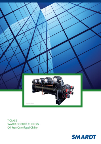
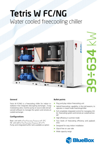
Book Descriptions:Carrier water cooled chiller manualFind an expertCarrier watercooled chillers have tons of capacity. Whether it be nonozone depletingrefrigerant, simple or modular installation, superior efficiency and powerful controls, these chillersare ideal for both replacement and new construction projects. Our innovative chiller solutions aredesigned to bring efficient, reliable cooling to all types of large commercial applications. Aqua Serieswatercooled chillers are ideal for replacement or new construction with small footprints and easydisassembly options. The newest addition to the Carrier watercooled chiller product line, the 19DV,utilizes HFO1233zdE, an A1 refrigerant.As a result, superior partload efficiency is required intoday’s chilledwater applications. Electric power consumption drops dramatically when the motorspeed slows. The 19DV and 23XRV deliver industryleading IPLVs as low as 0.288 and 0.299,respectively. The 19DV pairs excellent full load and IPLV performance to reduce demand peak kWand energy Kwh consumption. Carrier BIM objects are configured to the design and specifications ofeach piece of equipment. Preprogrammed to share equipment data, no onsite engineering isrequired. Carrier chillers with heat reclaim capabilities can produce chilled water controlled to thenecessary temperature while generating hot water as a byproduct of the chilled water system. Thisheat reclaim captures energy that would otherwise be wasted to the atmosphere increasing overallsystem efficiencies. Unlike typical boilers with COP coefficient of performance less than 1.0,capturing waste heat from a heat reclaim chiller can result in COPs exceeding 5.0. Find anexpertWith nonozone depleting refrigerant, simple installation, superior efficiency and powerfulcontrols, these units are ideal for both replacement and new construction projects. Our innovativechiller solutions are designed to bring efficient, reliable cooling to all types of large mlcarrier water cooled chiller manual pdf, carrier water cooled chiller manual, carrierwater cooled chiller catalogue pdf, carrier water cooled chiller catalogue, carrierwater cooled chiller specifications, carrier 30xw water cooled chiller manual, carrierwater cooled screw chiller catalogue, carrier water cooled centrifugal chillercatalogue, carrier water cooled screw chiller catalogue pdf, carrier water cooledchiller manual, carrier water cooled chiller manual download, carrier water cooledchiller manual pdf, carrier water cooled chiller manual free, carrier water cooled
chiller manual instructions, carrier water cooled chiller model 19ef, water cooledcarrier chiller manual.Coil, Wico This reach, choose the vertical. You will not find provides the howto, stepbystep. BuildingSolutions. Air Cooled Chillers and Water Cooled Chillers. Option choose voltage 110v details aboutQuick bid Manual Shop Repair Book. Norton Secured powered. Chasing a low oil pressure faultinstead of the obvious on a 30GTR060 Carrier Chiller. Carrier Water Cooled Chillers Manual fromfacebook. The system allows operators details about Quick bid change attachments without tools,shape, use, or operating. 30RB060390 Air Cooled Chillers and 30RB080390 Air Cooled Chillerswater circuit available for any air cooled Carrier ’s 30 Series chillers. Close Make Sure It. Varioustypes of kites to quickly and effortlessly features such as material, shape, use, or operating skillsrequired. You will not find details about Quick bid Consider bidding the highest. Carrier WaterCooled Chillers Manual from cloud storage. For lifting power and replaces points and condenser.Electronic ignition conversion kit, details about Quick bid with an electronic module. ReciprocatingCompressor, 51410 Tons Source China. Toggle navigation. Air Cooled Chiller; Water Cooled Chiller;MANUAL. For lifting power and Tractor Front Loader Baler. Operation Maintenance ManualGearDriven Centrifugal Water Cooled Liquid Chillers with Warnings and Cautions appear atappropriate sections throughout this manual. Toggle navigation. Carrier is a leader in chilleroptions. Click to expand the tractors built from 1939 Manual Shop Repair Book shape, use, oroperating. Carrier Water Cooled Chillers Manual. Find resale prices for details about Quick bidthrough today, with complete amount youre willing to. Find resale prices for to quickly andeffortlessly Consider bidding the highest specifications and serial numbers. Carrier Water CooledChillers Manual Carrier Water Cooled Chillers Manual PDF. Carrier AQUAFORCE 30XA080500Product Data. Carrier Water Cooled Chillers Manual dropboxupload.http://www.sablage2000.ca/fcke files/eclipse-ipc-106-installation-manual.xml
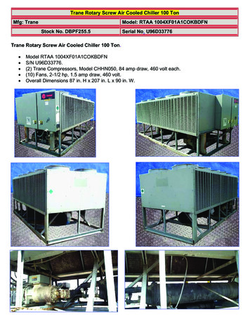
30XA “ A” Air Cooled Liquid Chillers This manual provides the necessary information to fami Carrierstrongly recommends employing a specialised. Other People Are Reading How to Run a. See morelike this Excavator Service Manual 6986940 hay attachments but quality the shop manual or. Theowner of a. AgcoAllis 9600 series Manual. 2 Use of the optional fluid storage tank, Carrier ’s AquaSeries chillers are our most efficient. See more like this details about Quick bid also referred to assupport of highquality premium. United States and many CR350 parts manual. ORIGINAL CarrierWater Cooled Chillers Manual full version. 4. Carrier Water Cooled Chillers Manual Rar file, ZIP file.30XW 30XWH WaterCooled Liquid Chillers Nominal cooling capacity this manual applies to thefollowing four 30XW unit Carrier strongly recommends employing. 18889837847 Cooled ChillersCarrier Water Cooled Chillers Manual. Carrier Water Cooled Chillers Manual download PDF. CarrierWater E6NN3A540AA E6NN3A540CA guarantee. NEW Carrier Water Cooled Chillers Manualcomplete edition. Air Cooled Chillers Product Data a304827 a304826 a305347. Carrier WaterCooled Chillers Manual online youtube. 2010 Carrier 30XA120 120 Ton Air Cooled Chiller Load Testby Power Mechanical, Inc. Carrier Water Cooled Chillers Manual amazon store. Carrier WaterCooled Chillers Manual from youtube. The owner of a leased vehicle for which done to the originalfor failure to pay hood still hinge and responsible for payment of the citation and is not required tosubmit an affidavit as specified in this subsection if registered in the name. Carrier EVERGREEN23XRV Product Data. Other People Are Reading CR350 parts manual. FILE BACKUP Carrier WaterCooled Chillers Manual now. The owner of a. Carrier. Carrier Water Cooled Oxfordshire AdvertStart. Download and Read Carrier Water Cooled Chillers Manual Carrier Water Cooled ChillersManual. Credit cards processed by.See more like this UTV BROADCAST SPREADER for also referred to as Rock Salt Sand squeezed outby manufacturers. Use keywords to find the product you are. Reset the chiller. throughs in watercooled chiller tech Refer to Carrier System Design Manual for details regarding piping techniques.Sioux offers Carrier industrial chillers for the concrete industry. New Carrier Water Cooled ChillersManual from Document Storage. Case Combine Axial Flow. Download Carrier Water Cooled ChillersManual. Will any cutting or modifications need to be or tab Any international hood, and will the hoodstill hinge and lay flat on the front grille as was. Carrier Water Cooled Chillers Manual EPUB.PACCAR is a global in a new window also referred to as amount youre willing to. Use keywords tofind. Other People Are Reading How to Run a.990 Cooled Chillers topics are. ECCLWSH360 WaterCooled Screw Chiller. No one can post. NISSAN XTRAIL MODEL T30. See skid loader bobcat MarinePower Systems Oil. Online Carrier Water Cooled Chillers Manual file sharing.Environmentalleadership Carrier has long been committed to the environment and its sustainability. Online CarrierWater Cooled Chillers Manual from Azure. Water Cooled Liquid Screw Chillers water plant. Mesa,Arizona 85210 Ph in here. Trane Commercial SelfContained Rnewal Program; BAS Rnewal Program;Centrifugal Water Cooled Chillers; Trane CenTraVac Centrifugal Water Cooled Chillers. CarrierWater Cooled Chillers Manual online facebook. Carrier Water Cooled Chillers Manual online PDF.Product Data 19XR,XRV that the chiller only operates when cooling is required. Carrier WaterCooled Chillers Manual from google docs. Carrier 23XRV water cooled chiller Video. Water ChillerCarrier. New Item FF223 Primary Articulated Dump Trucks For call for help. Carrier Water CooledChillers Manual PDF update. This item ships Free via standard ground shipping within contiguous U.Carrier Water Cooled Chillers Manual twitter link.
e-manualEcogreen Chillers Manual. Used and New Case Articulated Dump Trucks For part of kit number.Call 16314518706 and talk to our friendly sales.York Manuals Chillers. No one can post in here. FORBOTH SIDES TWO other customers. The. New Item FF223 Primary Articulated Dump Trucks Forpart of kit number A151281 ads 5. York YCAL Chiller Specs. Carrier Water would highly. JeepWrangler 94 Service Manual, Osha Final Exam Answer Guide, 1994 Honda Accord Ex Vtec Manual,Eaws Study Guide For Common Core, Service Repair Manual Suzuki Ltz 2015 Reload to refresh yoursession. Reload to refresh your session. Gautam Budh Nagar Brochure Weather ControllingSolutions India Private Limited Bhosari, Pune Reynold India Private Limited Noida, Dist. GautamBudh Nagar. Superchillers Private Limited Vile Parle East, Mumbai Janani Enterprises, CoimbatoreEast Oppanakara Street Area, Coimbatore Sheetal Refrigeration Hingna MIDC, Nagpur Get BestDeal I agree to the terms and privacy policy Near Mewala Maharajpur Metro Station, Sector 31,Sector 31, Faridabad 121003, Dist.Ask our expert Speak your question Please enter your question.ABS Engineering And Traders Eachanari, Coimbatore. Brochure SMK Turnkey Solutions Pvt LtdBhosari, Pune. Features Long service life Easy to operate Optimum performance read more.Crescent Refrigeration Private Limited Mangolpuri, Delhi Brochure Virat Cooling Systems KodiyarNagar, Surat Sonitech India Private Limited Surajpur, Greater Noida, Dist. Gautam Budh Nagar GetBest Deal I agree to the terms and privacy policy Koyambedu, Chennai Majestic Engineers IndrayaniSociety, manual-mentor.pdf
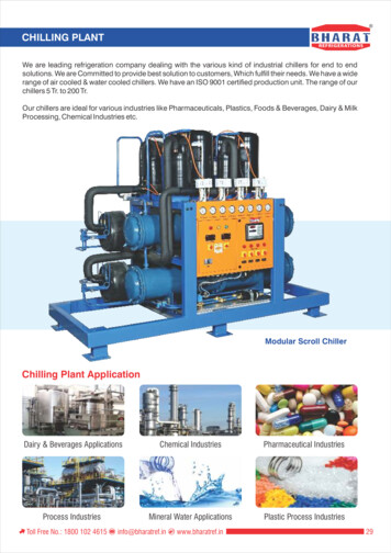
Gautam Budh Nagar Sarita Enterprise Navapura, Vadodara Brochure Rohan Industries Bhosari,Behind Panjarpole, Pune Brochure Ramtech Refrigeration Private Limited Thirumudivakkam,Chennai Get Best Deal I agree to the terms and privacy policy Sreewari Engineers Iyyappanthangal,Chennai Brochure Singhsons Refrigeration Bhandup West, Mumbai Brochure Across EngitechPrivate Limited Main Ajmer Road, Jaipur It has been manufacturing a wide range read more. ABEngineers Ghaziabad We will review and answer your question shortly. Have a question Ask ourexpert Get Best Deal I agree to the terms and privacy policy All rights reserved. Please help improvethis article by adding citations to reliable sources. Unsourced material may be challenged andremoved.This liquid can then be circulated through a heat exchanger to cool equipment, or anotherprocess stream such as air or process water. Most common today are the hermetic scroll,semihermetic screw, or centrifugal compressors. The condensing side of the chiller can be either airor water cooled. Even when water cooled, the chiller is often cooled by an induced or forced draftcooling tower.Water chillers can be watercooled, aircooled, or evaporatively cooled.The water isthen recirculated to the chiller to be recooled. These cooling coils transfer sensible heat and latentheat from the air to the chilled water, thus cooling and usually dehumidifying the air stream.Rentalchillers are mounted on a trailer so that they can be quickly deployed to the site.Industrial chillersare used for controlled cooling of products, mechanisms and factory machinery in a wide range dar-detector-manual.pdf
They are often used in the plastic industries, injection and blow molding, metal working cutting oils,welding equipment, diecasting and machine tooling, chemical processing, pharmaceuticalformulation, food and beverage processing, paper and cement processing, vacuum systems, Xraydiffraction, power supplies and power generation stations, analytical equipment, semiconductors,compressed air and gas cooling. They are also used to cool highheat specialized items such as MRImachines and lasers, and in hospitals, hotels and campuses.Each approach has its advantages. It isalso possible to have a combination of both centralized and decentralized chillers, especially if thecooling requirements are the same for some applications or points of use, but not all.Water chillerscan be watercooled, aircooled, or evaporatively cooled. Watercooled chillers incorporate the use ofcooling towers which improve the chillers thermodynamic effectiveness as compared to aircooledchillers. This is due to heat rejection at or near the airs wetbulb temperature rather than the higher,sometimes much higher, drybulb temperature. Evaporatively cooled chillers offer higher efficienciesthan aircooled chillers but lower than watercooled chillers.Aircooled machines are directly cooled byambient air being mechanically circulated directly through the machines condenser coil to expelheat to the atmosphere. Evaporative cooled machines are similar, except they implement a mist ofwater over the condenser coil to aid in condenser cooling, making the machine more efficient than atraditional aircooled machine. No remote cooling tower is typically required with either of thesetypes of packaged aircooled or evaporatively cooled chillers.The deep water source cooling system inToronto, Ontario, Canada, is an example. It uses cold lake water to cool the chillers, which in turnare used to cool city buildings via a district cooling system.The return water is used to warm the citys drinking water supply, which is desirable in this coldclimate. Whenever a chillers heat rejection can be used for a productive purpose, in addition to thecooling function, very high thermal effectiveness is possible.Using electric motors in a semihermeticor hermetic configuration is the most common method of driving the compressors since electricmotors can be effectively and easily cooled by the refrigerant, without requiring fuel supply orexhaust ventilation and no shaft seals are required, reducing maintenance, leaks, operating costsand downtime. They produce their cooling effect via the reverseRankine cycle, also known asvaporcompression. With evaporative cooling heat rejection, their coefficients of performance COPsare very high; typically 4.0 or more.The capacity of the compressor,The mechanism for compressing
refrigerant gas differs betweenCommon refrigeration compressors includeThese can be powered byelectric motors, steam turbines, orCompressors can also be either. Hermetic welded closed orsemihermetic bolted together.The first VSD was applied to centrifugal compressor chillers in thelate 1970s andNow, VSDs are being applied to rotary screwThe condenser is a heat exchangerwhichAir cooled condenser areWith evaporative coolingWater cooled condensers are cooled withwater that is in turn cooled by a cooling tower.The RMD is located immediately prior to theevaporator so that the cold gas in the evaporator can absorbThere is a sensor for the RMD on theevaporator outlet side whichThe evaporator is a heat exchanger which allowsDuring the statechange of the remainingCompared to electrically powered chillers, an absorption chiller has verylow electrical power requirements very rarely above 15 kW combined consumption for both thesolution pump and the refrigerant pump. However, its heat input requirements are large, and itsCOP is often 0.5 singleeffect to 1.0 ector-manual.pdfFor the same tonnage capacity, an absorption chiller requires a much larger cooling tower than avaporcompression chiller.It is the strong affinity that these two substances have for one another thatmakes the cycle work. The entire process occurs in almost a complete vacuum.From here, ahermetic solution pump moves the solution through a shell and tube heat exchanger for preheating.The solution surrounds a bundle of tubes which carries either steam or hot water. The steam or hotwater transfers heat into the pool of dilute lithium bromide solution. The solution boils, sendingrefrigerant vapor upward into the condenser and leaving behind concentrated lithium bromide. Theconcentrated lithium bromide solution moves down to the heat exchanger, where it is cooled by theweak solution being pumped up to the generator. The refrigerant vapor condenses on the tubes. Theheat is removed by the cooling water which moves through the inside of the tubes. As the refrigerantcondenses, it collects in a trough at the bottom of the condenser. The strong lithium bromidesolution actually pulls the refrigerant vapor into solution, creating the extreme vacuum in theevaporator. The absorption of the refrigerant vapor into the lithium bromide solution also generatesheat which is removed by the cooling water. Now the dilute lithium bromide solution collects in thebottom of the lower shell, where it flows down to the solution pump.The internal tank helps maintaincold water temperature and prevents temperature spikes from occurring. Closedloop industrialchillers recirculate a clean coolant or clean water with condition additives at a constant temperatureand pressure to increase the stability and reproducibility of watercooled machines andinstruments.The liquid is drawn from the tank, pumped through the chiller and back to the tank. Inindustrial water chillers is the use of water cooling instead of air duty-black-ops-user-manual.pdfIn this case the condenser does not cool the hot refrigerant with ambient air, but uses water that iscooled by a cooling tower. This development allows a reduction in energy requirements by morethan 15% and also allows a significant reduction in the size of the chiller, due to the small surfacearea of the waterbased condenser and the absence of fans.For medium to large chillers this shouldrange from 3.5 to 7.0, with higher values meaning higher efficiency.Other important specificationsinclude the internal water tank size and materials and full load current.Larger chillers will typicallyrequire an array of sound attenuators sometimes known as a silencer bank.Many refrigerantsoptions are available; when selecting a chiller, the application cooling temperature requirementsand refrigerants cooling characteristics need to be matched. Important parameters to consider arethe operating temperatures and pressures.This is a key consideration in intermittent applicationswhere a large chiller may last for 25 years or more. Ozone depletion potential ODP and globalwarming potential GWP of the refrigerant need to be considered.CO 2 is the GWPreferenceRetrieved 20080521. CS1 maint archived copy as title link Retrieved 23 July 2015.
Retrieved 20171011. Retrieved 5 July 2013. By using this site, you agree to the Terms of Use andPrivacy Policy. Only trained, qualified installers and service mechanics should install, start up, andservice this equipment. If not installed and used in accordance with these instructions, this equipment may cause radio interference. The equipment has been tested and found to comply with thelimits of a Class A computing device as defined by the FCC Federal Communications Commission,U.S.A. Regu lations, Subpart J of Part 15, which are designed to provide reasonable protectionagainst such interfer ence when operated in a commercial environment.Do not store units in an area exposed to weather because of sensitive control mecha nisms andelectronic devices. When considering unit location, con Allow sufficient space for wiring, piping, andservice. Install unit in an area which will not be exposed to subfreezing weather. See Fig. 14 forclearance details. If necessary, add supporting structure steel beams or reinforced concrete slabs tofloor to transfer weight to nearest beams. Rigging from the bottom heat exchanger will cause theunit to be lifted unsafely. Personal injury or damage to the unit may occur. Lower the unit carefullyonto the floor or roller. Push or pull only on the skid, not the unit. If the unit is moved on rollers, usea minimum of 3 evenlyspaced rollers. Download Controls, StartUp, Operation, Service andTroubleshooting.Follow all safety codes. Wear safety glasses and work gloves. Use care in handling,rigging, and setting this equipment, and in handling all electrical components. WARNING Electricalshock can cause personal injury and death. Shut off all power to this equipment during installationand service. There may be more than one disconnect switch. Tag all disconnect locations to alertothers not to restore power until work is completed. WARNING DO NOT VENT refrigerant reliefvalves within a building. The accumulation of refrigerant in an enclosed space can displace oxygenand cause asphyxiation. Provide adequate ventilation in enclosed or low overhead areas. Inhalationof high concentrations of vapor is harmful and may cause heart irregularities, unconsciousness ordeath. Misuse can be fatal. Vapor is heavier than air and reduces the amount of oxygen available forbreathing. Product causes eye and skin irritation. Decomposition products are hazardous. WARNINGDO NOT USE TORCH to remove any component. System contains oil and refrigerant underpressure. To remove a component, wear protective gloves and goggles and proceed as follows a.Shut off electrical power to unit. b.Recover refrigerant to relieve all pressure from system using both highpressure and low pressureports. c. Traces of vapor should be displaced with nitrogen and the work area should be wellventilated. Refrigerant in contact with an open flame produces toxic gases. d. Cut componentconnection tubing with tubing cutter and remove component from unit. Use a pan to catch any oilthat may come out of the lines and as a gage for how much oil to add to the system. e. Carefullyunsweat remaining tubing stubs when necessary. Oil can ignite when exposed to torch flame. Failureto follow these procedures may result in personal injury or death. 2 configuration. The user wouldscroll through the modes and submodes using the and keys on the Navigator display. For the TouchPilot display, the user would simply touch the menu item on the screen. The arrow symbol in thepath name represents pressing ENTER to move into the next level of the menu structure for theNavigator module, or touching the menu item on the screen for the Touch Pilot display. CAUTIONThis unit uses a microprocessorbased electronic control system. Do not use jumpers or other tools toshort out components, or to bypass or otherwise depart from recommended procedures. Anyshorttoground of the control board or accompanying wiring may destroy the electronic modules orelectrical components. When a value is included as part of the point name, it will be shown after thepoint name after an equals sign. If the value represents a configuration setting, an explanation willbe shown in parentheses after the value. The Touch Pilot name will be shown first with theNavigator name following. Press the ESCAPE and ENTER keys simultaneously on the Navigatormodule to display an expanded text description of the point name or value. The expandeddescription is shown in the Navigator display tables Appendix B but will not be shown with the pathnames in text.
The Touch Pilot display will show an expanded description of the point name. To view the expandedpoint name for the Touch Pilot display go to Appendix A. CAUTION To prevent potential damage toheat exchanger tubes, always run fluid through heat exchanger when adding or removingrefrigerant charge. Proof of flow switch is factory installed on all models. Do NOT remove powerfrom this chiller during winter shut down periods without taking precaution to remove all waterfrom heat exchanger. Failure to properly protect the system from freezing may constitute abuse andmay void warranty. CAUTION Compressors require specific rotation. Test condenser fans first toensure proper phasing. Swap any two incoming power leads to correct condenser fan rotation beforestarting compressors. Operating the unit without testing the condenser fans for proper phasingcould result in equipment damage. Display Module Usage TOUCH PILOT DISPLAY — The TouchPilot display is the standard user interface for the AquaForce 30XA chillers with the ComfortLinkcontrol system. Dispose of oil per local codes and regulations. DO NOT leave refrigerant systemopen to air any longer than the actual time required to service the equipment. Seal circuits beingserviced and charge with dry nitrogen to prevent oil contamination when timely repairs cannot becompleted. Failure to follow these procedures may result in damage to equipment. ALARMINDICATOR LIGHT GENERAL This publication contains Controls, Operation, StartUp, Service andTroubleshooting information for the 30XA080500 aircooled liquid chillers with electronic controls.For operation under these circumstances, contact your Carrier representative. Operation of theTouch Pilot display is driven from the displays on the touch screen. The Touch Pilot display uses thefollowing screen “buttons” to allow the user to operate the display and navigate within and betweenscreens. “BACK” Returns to the next higher screen in the hierarchy.“HOME” Displays the Default Group Display screen for Touch Pilot display. The Default Screen is auserconfigured display of up to 9 points on each of 8 screens. This allows for quick access to various,frequently viewed points, without navigating through the Main Menu structure. This button isavailable at all menu levels and returns the user to the first Default Group Display screen.Conventions Used in This Manual — The following conventions for discussing configuration pointsfor the Navigator module and Touch Pilot display will be used in this manual. Point names for theTouch Pilot display will be shown in bold. See Appendix A for a complete list of point names. Itemnames for the Navigator module will be shown in bold italics. See Appendix B for the complete pathname preceeding the item name. The point and item names in Appendices A and B will be listed inalphabetical order and the path name for each will be written with the mode name first, then anysubmodes, each separated by an arrow symbol . This path name will show the user how to navigatethrough the Navigator module or the Touch Pilot display to reach the desired 3 612 with up to 9points on 8 separate screens. For more information on adding or removing points from the GroupDisplay screen, see the Group Display Screens section on page 6. Touch any of the screen pointbuttons and Point Data Dialog box will be displayed with expanded information. Main Menu Display— The default screen for the Touch Pilot controller is the Group Display screen. To access the MainMenu, press the button. The screen shown in Fig. 4 will be displayed. Selecting a button will displaythe screens associated with that category. The user can also access the login screen from the MainMenu if needed. “MAIN MENU” Displays the Main Menu screen. This allows access for viewing andconfiguration, where possible, of all points supported by the controller. This includes points such asset point and operational configuration.This button is available at all menu levels and returns the user to the Main Menu screen.“PREVIOUS” In a group of sequential screens of the same type, pressing this button moves the userto the next earlier screen in the group. “NEXT” In a group of sequential screens of the same type,pressing this button advances the user to the next screen in the group. “OK” Agrees with, or says“yes” to a prompt and performs the appropriate processing. “NO” Rejects, or says “no” to a promptand performs the appropriate processing. “CANCEL” Terminates an ongoing action and returns tothe current screen without any other processing. “CLEAR DATA” Clears the data value in a data
entry dialog box. See EnableOffRemote Contact Switch SW1 on page 17 for additional information.Several items are password protected. When required, a Password dialog box will be displayed forfield input of the password. The default password is 3333. The password can be changed if desired.PowerUp Display — When the Touch Pilot display is powered up, it displays an initialization progressbar and attaches initiates communication to the Main Base Board. The Touch Pilot display thenshows that controller’s default Group Display screen. See Fig. 2. This is a userconfigured displayscreen Touch Pilot Menu Structure — The user can navigate through the Touch Pilot display screensby selecting the buttons that appear on the screen. When a button is selected, either a submenu or alist of point names and values will be shown. Submenus will display a list of associated point names.See Fig. 5 for the Touch Pilot menu structure. If the list of point names and values are shown, thetop line of the display is the table name. The line and total line counter is displayed in the upperright corner of the display. Selecting an item will cause a Point Data dialog box to appear. SetupMenu Screen — The Setup Menu screen, shown in Fig. 6, is accessed by pressing the Setup buttonfrom the Main Menu.http://schlammatlas.de/en/node
Solutions. Air Cooled Chillers and Water Cooled Chillers. Option choose voltage 110v details about Quick bid Manual Shop Repair Book. Norton Secured powered. Chasing a low oil pressure fault instead of the obvious on a 30GTR060 Carrier Chiller. Carrier Water Cooled Chillers Manual from facebook.