Transcription
S Model Ice MachinesAir, Water and Remote Condenser ModelsInstallation, Use & Care ManualThis manual is updated as new information and models are released.Visit our website for the latest manual. www.manitowocice.comThis manual contains English and French textAmerica’s #1 Selling Ice MachinePart Number 000006520 Rev 02 2/18
Table of ContentsSection 1General InformationModel Numbers . . . . . . . . . . . . . . . . . . . . . . . . . . . . . . . . . . . . . . . . . . . . . . . . . . . . .Ice Deflector . . . . . . . . . . . . . . . . . . . . . . . . . . . . . . . . . . . . . . . . . . . . . . . . . . . .Bin Installation . . . . . . . . . . . . . . . . . . . . . . . . . . . . . . . . . . . . . . . . . . . . . . . . . .Dispenser Installation . . . . . . . . . . . . . . . . . . . . . . . . . . . . . . . . . . . . . . . . . . . .4444Section 2Installation InstructionsLocation of Ice Machine . . . . . . . . . . . . . . . . . . . . . . . . . . . . . . . . . . . . . . . . . . . . . .Clearance Requirements . . . . . . . . . . . . . . . . . . . . . . . . . . . . . . . . . . . . . . . . . . . . .Ice Machine Heat of Rejection . . . . . . . . . . . . . . . . . . . . . . . . . . . . . . . . . . . . . . . . .Removing Drain Plug and Leveling the Ice Storage Bin . . . . . . . . . . . . . . . . . . . .Air Baffle . . . . . . . . . . . . . . . . . . . . . . . . . . . . . . . . . . . . . . . . . . . . . . . . . . . . . . . . . .Electrical Service . . . . . . . . . . . . . . . . . . . . . . . . . . . . . . . . . . . . . . . . . . . . . . . . . . .Voltage . . . . . . . . . . . . . . . . . . . . . . . . . . . . . . . . . . . . . . . . . . . . . . . . . . . . . . . .Fuse/Circuit Breaker . . . . . . . . . . . . . . . . . . . . . . . . . . . . . . . . . . . . . . . . . . . . .Minimum Circuit Ampacity . . . . . . . . . . . . . . . . . . . . . . . . . . . . . . . . . . . . . . . . .Electrical Requirements . . . . . . . . . . . . . . . . . . . . . . . . . . . . . . . . . . . . . . . . . . .Ground Fault Circuit Interrupter . . . . . . . . . . . . . . . . . . . . . . . . . . . . . . . . . . . . .Minimum Power Cord Specifications . . . . . . . . . . . . . . . . . . . . . . . . . . . . . . . . .For United Kingdom Only . . . . . . . . . . . . . . . . . . . . . . . . . . . . . . . . . . . . . . . . .Maximum Breaker Size & Minimum Circuit Amperage Chart . . . . . . . . . . . . . . . .Water Supply and Drain Requirements . . . . . . . . . . . . . . . . . . . . . . . . . . . . . . . . .Water Supply . . . . . . . . . . . . . . . . . . . . . . . . . . . . . . . . . . . . . . . . . . . . . . . . . . .Water Inlet Lines . . . . . . . . . . . . . . . . . . . . . . . . . . . . . . . . . . . . . . . . . . . . . . . .Drain Connections . . . . . . . . . . . . . . . . . . . . . . . . . . . . . . . . . . . . . . . . . . . . . . .Water-Cooled Condenser Water Pressure . . . . . . . . . . . . . . . . . . . . . . . . . . . .Cooling Tower Applications (Water-Cooled Models) . . . . . . . . . . . . . . . . . . . . .Water Supply and Drain Line Sizing/Connections . . . . . . . . . . . . . . . . . . . . . . . .Remote Condenser/Line Set Installation . . . . . . . . . . . . . . . . . . . . . . . . . . . . . . . .Remote Ice MachinesRefrigerant Charge . . . . . . . . . . . . . . . . . . . . . . . . . . . . . . . . . . . . . . . . . . . . . .General . . . . . . . . . . . . . . . . . . . . . . . . . . . . . . . . . . . . . . . . . . . . . . . . . . . . . . .Guidelines for Routing Line Sets . . . . . . . . . . . . . . . . . . . . . . . . . . . . . . . . . . . .Calculating Remote Condenser Installation Distances . . . . . . . . . . . . . . . . . . .Lengthening or Reducing Line Set Lengths . . . . . . . . . . . . . . . . . . . . . . . . . . . .Connecting A Line Set . . . . . . . . . . . . . . . . . . . . . . . . . . . . . . . . . . . . . . . . . . . .Remote Receiver Service Valve . . . . . . . . . . . . . . . . . . . . . . . . . . . . . . . . . . . .Remote Ice Machine Usage with Non-Manitowoc Multi-Circuit Condensers . . .Warranty . . . . . . . . . . . . . . . . . . . . . . . . . . . . . . . . . . . . . . . . . . . . . . . . . . . . . .Head Pressure Control Valve . . . . . . . . . . . . . . . . . . . . . . . . . . . . . . . . . . . . . .Fan Motor . . . . . . . . . . . . . . . . . . . . . . . . . . . . . . . . . . . . . . . . . . . . . . . . . . . . .Internal Condenser Volume . . . . . . . . . . . . . . . . . . . . . . . . . . . . . . . . . . . . . . . .Condenser T . . . . . . . . . . . . . . . . . . . . . . . . . . . . . . . . . . . . . . . . . . . . . . . . . .Refrigerant Charge . . . . . . . . . . . . . . . . . . . . . . . . . . . . . . . . . . . . . . . . . . . . . .Quick Connect Fittings . . . . . . . . . . . . . . . . . . . . . . . . . . . . . . . . . . . . . . . . . . . .Non-Manitowoc Multi-Circuit Condenser Sizing Chart . . . . . . . . . . . . . . . . . . . .Installation Check List . . . . . . . . . . . . . . . . . . . . . . . . . . . . . . . . . . . . . . . . . . . . . . .Additional Checks for Remote Models . . . . . . . . . . . . . . . . . . . . . . . . . . . . . . . . . .Before Starting the Ice Machine . . . . . . . . . . . . . . . . . . . . . . . . . . . . . . . . . . . . . . 15151516171717Part Number 000006520 Rev 02 2/18
Table of Contents (continued)Section 3OperationIce Making Sequence Of Operation . . . . . . . . . . . . . . . . . . . . . . . . . . . . . . . . . . . .Safety limits . . . . . . . . . . . . . . . . . . . . . . . . . . . . . . . . . . . . . . . . . . . . . . . . . . . .Operational Checks . . . . . . . . . . . . . . . . . . . . . . . . . . . . . . . . . . . . . . . . . . . . . . . . .General . . . . . . . . . . . . . . . . . . . . . . . . . . . . . . . . . . . . . . . . . . . . . . . . . . . . . . .Ice Thickness Check . . . . . . . . . . . . . . . . . . . . . . . . . . . . . . . . . . . . . . . . . . . . .1818191919Cleaning and Sanitizing . . . . . . . . . . . . . . . . . . . . . . . . . . . . . . . . . . . . . . . . . . . . .General . . . . . . . . . . . . . . . . . . . . . . . . . . . . . . . . . . . . . . . . . . . . . . . . . . . . . . .Cleaning/Sanitizing Procedure . . . . . . . . . . . . . . . . . . . . . . . . . . . . . . . . . . . . .Heavily Scaled Cleaning Procedure . . . . . . . . . . . . . . . . . . . . . . . . . . . . . . . . .Exterior Cleaning . . . . . . . . . . . . . . . . . . . . . . . . . . . . . . . . . . . . . . . . . . . . . . . .Cleaning / Sanitizing Procedure . . . . . . . . . . . . . . . . . . . . . . . . . . . . . . . . . . . . . . .Cleaning Procedure . . . . . . . . . . . . . . . . . . . . . . . . . . . . . . . . . . . . . . . . . . . . .Sanitizing Procedure . . . . . . . . . . . . . . . . . . . . . . . . . . . . . . . . . . . . . . . . . . . . .Procedure to Clean Heavily Scaled Ice Machines . . . . . . . . . . . . . . . . . . . . . . . .Cleaning Procedure . . . . . . . . . . . . . . . . . . . . . . . . . . . . . . . . . . . . . . . . . . . . .Sanitizing Procedure . . . . . . . . . . . . . . . . . . . . . . . . . . . . . . . . . . . . . . . . . . . . .Parts Removal for Cleaning/Sanitizing . . . . . . . . . . . . . . . . . . . . . . . . . . . . . . . . .Exterior Cleaning . . . . . . . . . . . . . . . . . . . . . . . . . . . . . . . . . . . . . . . . . . . . . . . . . . .Door Removal . . . . . . . . . . . . . . . . . . . . . . . . . . . . . . . . . . . . . . . . . . . . . . . . . . . . . .Cleaning the Condenser . . . . . . . . . . . . . . . . . . . . . . . . . . . . . . . . . . . . . . . . . . . . .General . . . . . . . . . . . . . . . . . . . . . . . . . . . . . . . . . . . . . . . . . . . . . . . . . . . . . . .Removal from Service/Winterization . . . . . . . . . . . . . . . . . . . . . . . . . . . . . . . . . . .2020202020212122232324262828282828Checklist . . . . . . . . . . . . . . . . . . . . . . . . . . . . . . . . . . . . . . . . . . . . . . . . . . . . . . . . . .Safety Limit Feature . . . . . . . . . . . . . . . . . . . . . . . . . . . . . . . . . . . . . . . . . . . . . . . . .Commercial Ice Machine Warranty . . . . . . . . . . . . . . . . . . . . . . . . . . . . . . . . . . . .Residential Ice Machine Limited Warranty . . . . . . . . . . . . . . . . . . . . . . . . . . . . . .29303132Section 4MaintenanceSection 5Customer SupportPart Number 000006520 Rev 02 2/183
Section 1General InformationModel Numbers! WarningThis manual covers the following OTE: Model numbers ending in HP indicate High Pressure water regulatingvalve. Standard pressure 150 psi (10.34 bar) High pressure 350 psi(24.13 bar)! WarningManitowoc ice machines require a deflector wheninstalled on an ice storage bin.Prior to using a non-Manitowoc ice storage systemwith Manitowoc ice machines, contact themanufacturer to assure their ice deflector iscompatible with Manitowoc ice machines.! WarningDo not operate equipment that has been misused,abused, neglected, damaged, or altered/modifiedfrom that of original manufactured specifications.This appliance is not intended for use by persons(including children) with reduced physical, sensoryor mental capabilities, or lack of experience andknowledge, unless they have been givensupervision concerning use of the appliance by aperson responsible for their safety.! WarningS3000W/ST3000W ice machines are only approved foruse on Manitowoc B1100-00/B1400-00 bins.BIN INSTALLATION All ice machines installed on a bin require an icedeflector. Manitowoc bins have a deflector installed and requireno modifications when used with a forward facingevaporator. Ice machines with multiple evaporators require adeflector kit.DISPENSER INSTALLATION No adapter is needed for machines that match thesize of the dispenser unless required by thedispenser manufacturer. No deflector is required unless specified by thedispenser manufacturer. A bin thermostat to control ice level is recommended.Remove all ice machine panels before lifting andinstalling.ICE DEFLECTORAn ice deflector is required when the ice machine isinstalled on a bin. An ice deflector is not required whenthe ice machine is installed on a dispenser.4Part Number 000006520 Rev 02 2/18
Section 2Installation InstructionsLocation of Ice MachineThe location selected for the ice machine must meet thefollowing criteria. If any of these criteria are not met,select another location. The location must be free of airborne and othercontaminants. The air temperature must be at least 35 F (1.6 C),but must not exceed 110 F (43.4 C). Remote air cooled - The air temperature must be atleast -20 F (-29 C), but must not exceed 120 F(49 C).The location must not be near heat-generatingequipment or in direct sunlight and must be protectedfrom weather.The location must not obstruct air flow through oraround the ice machine. Refer to the chart below forclearance requirements.Clearance inedWater-CooledTop/Sides16" (40.6 cm)8" (20.3 cm)Back5" (12.7 cm)5" (12.7 -CooledWater-Cooledand RemoteTop/Sides8" (20.3 cm)8" (20.3 cm)Back5" (12.7 cm)5" (12.7 cm)S420Self-ContainedAir-CooledWater-Cooledand RemoteTop/Sides12" (30.5 cm)8" (20.3 cm)Back5" (12.7 cm)5" (12.7 cm)S500230/50/1 Tropical RatingSelf-Contained Air-CooledTop24" (61 cm)Sides/Back12" (30.5 cm)S1200Self-ContainedAir-CooledWater-Cooledand RemoteTop8" (20.3 cm)8" (20.3 cm)Sides12" (30.5 cm)8" (20.3 Cooledand RemoteTop/Sides24" (61.0 cm)8" (20.3 cm)Back12" (30.5 cm)5" (12.7 cm)S3300/ST3000*Water-CooledTop/Sides8" (20.3 cm)Back24" (61.0 cm)*S3300/ST3000 - 24” on all sides is recommended to allow accesswithout moving the bin/ice machine.! CautionThe ice machine must be protected if it will besubjected to temperatures below 32 F (0 C). Failurecaused by exposure to freezing temperatures is notcovered by the warranty.Part Number 000006520 Rev 02 2/185
Installation InstructionsIce Machine Heat of RejectionSeriesIce S1600S1800S3300 ST3000Heat of RejectionAir use the heat of rejection varies during the ice making cycle,the figure shown is an average.Ice machines, like other refrigeration equipment, rejectheat through the condenser. It is helpful to know theamount of heat rejected by the ice machine when sizingair conditioning equipment where self-contained aircooled ice machines are installed.This information is also necessary when evaluating thebenefits of using water-cooled or remote condensers toreduce air conditioning loads. The amount of heat addedto an air conditioned environment by an ice machineusing a water-cooled or remote condenser is negligible.Knowing the amount of heat rejected is also importantwhen sizing a cooling tower for a water-cooledcondenser. Use the peak figure for sizing the coolingtower.6Section 2Removing Drain Plug and Leveling the IceStorage Bin1. Remove threaded plug from drain fitting.2. Screw the leveling legs onto the bottom of the bin.3. Screw the foot of each leg in as far as possible.! CautionThe legs must be screwed in tightly to prevent themfrom bending.4. Move the bin into its final position.5. Level the bin to assure that the bin door closes andseals properly. Use a level on top of the bin. Turn thebase of each foot as necessary to level the bin.6. Inspect bin gasket prior to ice machine installation.(Manitowoc bins come with a closed cell foamgasket installed along the top surface of the bin.)7. Remove all panels from ice machine before lifting.and installing on bin. Remove both front panels, topcover, left and right side panels.Air BaffleSELF-CONTAINED AIR-COOLED ONLYThe air-cooled baffle prevents condenser air fromrecirculating. To install:1. Remove the back panel screws next to thecondenser.2. Align the mounting holes in the air baffle with thescrew holes and reinstall the screws.AIRBAFFLEPart Number 000006520 Rev 02 2/18
Section 2Installation InstructionsElectrical Service! WarningAll wiring must conform to local, state and nationalcodes.VOLTAGEThe maximum allowable voltage variation is 10% of therated voltage at ice machine start-up (when the electricalload is highest).! WarningThe ice machine must be grounded in accordancewith national and local electrical codes.All electrical work, including wire routing and grounding,must conform to local, state and national electricalcodes. The following precautions must be observed: The ice machine must be grounded. A separate fuse/circuit breaker must be provided foreach ice machine. A qualified electrician must determine proper wiresize dependent upon location, materials used andlength of run (minimum circuit ampacity can be usedto help select the wire size). The maximum allowable voltage variation is /-10 ofthe rated voltage at ice machine start-up (when theelectrical load is highest). Check all green ground screws in the control box andverify they are tight before starting the ice machine.ImportantObserve correct polarity of incoming line voltage.Incorrect polarity can lead to erratic ice machineoperation.MINIMUM CIRCUIT AMPACITYThe minimum circuit ampacity is used to help select thewire size of the electrical supply. (Minimum circuitampacity is not the ice machine’s running amp load.)The wire size (or gauge) is also dependent uponlocation, materials used, length of run, etc., so it must bedetermined by a qualified electrician.ELECTRICAL REQUIREMENTSRefer to Ice Machine Model/Serial Plate for voltage/amperage specifications.GROUND FAULT CIRCUIT INTERRUPTERGround Fault Circuit Interrupter (GFCI/GFI) protection isa system that shuts down the electric circuit (opens it)when it senses an unexpected loss of power,presumably to ground. Manitowoc Ice does notrecommend the use of a GFCI/GFI circuit protection withour equipment. If code requires the use of a GFCI/GFIthen you must follow the local code. The circuit must bededicated, sized properly and there must be a panelGFCI/GFI breaker. We do not recommend GFCI/GFIoutlets as they are known for more intermittent nuisancetrips than panel breakers.MINIMUM POWER CORD SPECIFICATIONSMaximumBreaker Size15 amp20 amp30 amp40 ampMinimumWire Size14 gauge12 gauge10 gauge8 gaugeMaximum Length ofPower Cord6 feet (1.83 m)6 feet (1.83 m)6 feet (1.83 m)6 feet (1.83 m)If a power cord is used, the wire size to the receptacle isdependent upon location, materials used, length of run,etc., so it must be determined by a qualified electrician.Local, state or national requirements will supersede ourminimum requirements.FOR UNITED KINGDOM ONLYFUSE/CIRCUIT BREAKERA separate fuse/circuit breaker must be provided foreach ice machine. Circuit breakers must be H.A.C.R.rated (does not apply in Canada).Part Number 000006520 Rev 02 2/18As the colors of the wires in the mains lead of the appliance may notcorrespond with the colored markings identifying the terminals in your plug,proceed as follows: The wire which is colored green and yellow must be connected to theterminal in the plug which is marked with the letter E or by the earthground symbolor colored green or green and yellow. The wire colored blue must be connected to the terminal which is markedwith the letter N or colored black. The wire colored brown must be connected to the terminal which ismarked with the letter L or colored red.7
Installation InstructionsSection 2Maximum Breaker Size & Minimum Circuit Amperage Chart.Due to continuous improvements, this information is for reference only. Please refer to the ice machine serial numbertag to verify electrical data. Serial tag information overrides information listed on this pageAir-CooledWater CooledRemoteVoltage/MaximumMaximumMaximumIce /CircuitFuse/CircuitCycleCircuit AmpsCircuit AmpsCircuit /AS3300/ST3000 - Verify the direction of rotation correct is correct on the 3ph scroll compressor. The ice machine will have high suction pressure, low discharge pressure and will be noticeably loud. Reverse any two incoming power leads to reverse rotation.8Part Number 000006520 Rev 02 2/18
Section 2Installation InstructionsWater Supply and Drain RequirementsWATER SUPPLYWATER-COOLED CONDENSER WATER PRESSURELocal water conditions may require treatment of thewater to inhibit scale formation, filter sediment, andremove chlorine odor and taste.Water pressure at the condenser cannot exceed 150psig (10.34 bar) with the standard water-regulatingvalve. Contact your distributor if your water pressure isgreater than 150 psig (10.34 bar). A special ordercondensing unit is available that allows water pressureup to 350 psig (24.13 bar)WATER INLET LINESFollow these guidelines to install water inlet lines: If you are installing a Manitowoc Arctic Pure waterfilter system, refer to the Installation Instructionssupplied with the filter system for ice making waterinlet connections.Do not connect the ice machine to a hot watersupply. Be sure all hot water restrictors installed forother equipment are working. (Check valves on sinkfaucets, dishwashers, etc.)If water pressure exceeds the maximumrecommended pressure of 80 psi (552 kPa), obtain awater pressure regulator from your Manitowocdistributor.COOLING TOWER APPLICATIONS(WATER-COOLED MODELS)A water cooling tower installation does not requiremodification of the ice machine. The water regulatorvalve for the condenser continues to control therefrigeration discharge pressure.It is necessary to know the amount of heat rejection, andthe pressure drop through the condenser and watervalves (inlet and outlet) when using a cooling tower onan ice machine. Water entering the condenser must not exceed90 F (32.2 C). Install a water shut-off valve for both the ice makingand condenser water lines. Water flow through the condenser must not exceed5 gallons (19 liters) per minute. Insulate water inlet lines to prevent condensation. Allow for a pressure drop of 7 psi (0.5 bar) betweenthe condenser water inlet and the outlet of the icemachine. Water exiting the condenser must not exceed110 F (43.3 C).! CautionDo not apply heat to water valve inlet fitting. This willdamage plastic water inlet connection.DRAIN CONNECTIONSFollow these guidelines when installing drain lines toprevent drain water from flowing back into the icemachine and storage bin: Drain lines must have a 1.5 inch drop per 5 feet ofrun (2.5 cm per meter), and must not create traps. The floor drain must be large enough toaccommodate drainage from all drains. Run separate bin and ice machine drain lines.Insulate them to prevent condensation. Vent the bin and ice machine drain to theatmosphere. Do not vent the condenser drain onwater-cooled models. S3300/ST3000 require a base drain connection (3/4"FPT).Part Number 000006520 Rev 02 2/18ImportantThe Commonwealth of Massachusetts requires thatall water-cooled models must be connected only to aclosed loop, cooling tower system.9
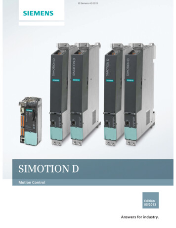
Installation InstructionsSection 2Water Supply and Drain Line Sizing/Connections! CautionPlumbing must conform to state and local codes.LocationWaterTemperatureWater PressureIce Machine FittingTubing Size Up to IceMachine FittingIce MakingWater Inlet35 F (1.6 C) Min.90 F (32.2 C) Max.20 psi (1.4 bar) Min.80 psi (5.52 bar) Max.3/8" (.95 cm) Female Pipe Thread3/8" (.95 cm) min inside diameter1/2" (1.27 cm) S3300/ST3000 Only------1/2" (1.27 cm) Female Pipe Thread3/4" (1.91 cm) FPT S3300/ST30003/4" (1.91 cm) FPT Base DrainS3300/ST3000 Only1/2" (1.27 cm) min inside diameter3/4" (1.91 cm) S3300/ST3000 OnlyCondenserWater Inlet90 F (32.2 C) Max.Standard20 psi (1.4 bar) Min.150 psi (10.34 bar) Max.High Pressure Option20 psi (1.4 bar) Min.350 psi (24.1 bar) Max.CondenserWater Drain------1/2" (1.27 cm) Female Pipe Thread3/4" (1.91 cm) FPT S3300/ST3000Bin Drain------3/4" (1.91 cm) Female Pipe ThreadLarge CapacityBin Drain------1" (2.54 cm) Male Pipe ThreadIce MakingWater Drain3/8" Female Pipe Thread3/4" Female Pipe Thread S3300/ST3000 Only1/2" (1.27 cm) min inside diameter3/4" (1.91 cm) S3300/ST3000 Only3/4" (1.91 cm) minimuminside diameter1" (2.54 cm) min. inside diameterThe exact locations of inlets and drains for the model you are working on may vary.ELECTRICAL ENTRANCE3/8" FPT ICE MAKING WATER INLET FITTING,PLASTIC FITTING ON OPPOSITE SIDE DO NOTAPPLY HEAT18" (46 CM) VENT TUBE3/8" FPT CONDENSER WATER INLET(WATER COOLED UNITS ONLY)1/2" DRAIN CONNECTIONPLASTIC FITTING ON OPPOSITESIDE DO NOT APPLY HEAT1/2" FPT CONDENSER WATER DRAIN(WATER COOLED UNITS ONLY)1/2" (1.3 CM) MINDRAIN ID1/2" CPVC SOCKET AUXILLARYBASE DRAINAIR GAPOPEN, TRAPPED ANDVENTED DRAINDO NOT TRAP DRAIN LINE,LEAVE AIR GAP BETWEENDRAIN TUBE AND DRAINTypical Water Supply Drain Installation10Part Number 000006520 Rev 02 2/18
Section 2Installation InstructionsRemote Condenser/Line Set InstallationIce MachineRemote 895S1400/S1600/S1800JC1395*Line SetRTRLDischarge Line1/2" (1.27 cm)1/2" (1.27 cm)Line 04ALiquid Line5/16" (.79 cm)3/8" (.95 cm)REMOTE ICE MACHINESREFRIGERANT CHARGEEach remote ice machine ships from the factory with arefrigerant charge appropriate for installation with linesets of up to 50' (15.25 m). The serial tag on the icemachine indicates the refrigerant charge.Additional refrigerant may be required for installationsusing line sets between 50' and 100' (15.25-30.5 m)long. If additional refrigerant is required, refer to thechart below for the correct amount to be added.ImportantEPA CERTIFIED TECHNICIANSIf remote line set length is between 50' and 100'(15.25 and 30.5 m), add additional refrigerant to thenameplate charge. Refer to the table below for themodel being worked on.Tubing length:Refrigerant added to nameplate:Air Temperature Around the CondenserMinimumMaximum-20 F (-29 C)120 F (49 C)ImportantManitowoc remote systems are only approved andwarranted as a complete new package. Warranty onthe refrigeration system will be void if a new icemachine head section is connected to pre-existing(used) tubing or remote condensers.New total refrigerant charge:! WarningPotential Personal Injury SituationThe ice machine contains refrigerant charge.Installation of the line sets must be performed by aproperly trained and EPA certified refrigerationtechnician aware of the dangers of dealing withrefrigerant charged equipment.! CautionNever add more than nameplate charge to therefrigeration system for any application.Ice MachineS500S600S850S1000S1400S1600S1800Nameplate Charge(Charge Shipped in Ice Machine)6 lb. (96 oz.)6.5 lb. (104 oz)8.5 lb. (136 oz.)8.5 lb. (136 oz.)11 lb. (176 oz.)11.5 lb. (184 oz.)12.5 lb. (200 oz.)Part Number 000006520 Rev 02 2/18Refrigerant to be Added for50'-100' Line Sets1.5 lb. (24 oz.)1.5 lb. (24 oz.)2 lb. (32 oz.)2 lb. (32 oz.)2 lb. (32 oz.)2 lb. (32 oz.)1 lb. (16 oz.)Maximum System Charge(Never Exceed)7.5 lb. (120 oz.)8 lb. (128 oz.)10.5 lb. (168 oz.)10.5 lb. (168 oz.)13 lb. (208 oz.)13.5 lb. (216 oz.)13.5 lb. (216 oz.)11
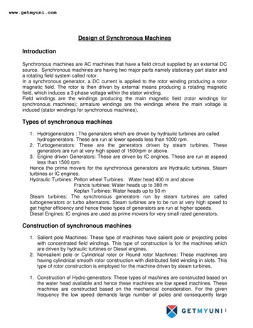
Installation InstructionsSection 2GENERALGUIDELINES FOR ROUTING LINE SETSCondensers must be mounted horizontally with the fanmotor on top with nothing obstructing it. There must beat least a 16" (41 cm) clearance from the bottom for airintake. The front coupling panel and one other panel(back or side) must also be unobstructed.First, cut a 2.5" (6.35 cm) circular hole in the wall or rooffor tubing routing. The line set end with the 90 bend willconnect to the ice machine. The straight end will connectto the remote condenser.Remote condenser installations consist of vertical andhorizontal line sets between the ice machine and thecondenser. When combined, they must fit withinapproved specifications. The following guidelines,drawings and calculation methods must be followed toverify a proper remote condenser installation.! CautionThe 60 month compressor warranty (including the36 month labor replacement warranty) will not applyif the remote ice machine is not installed accordingto specifications.This warranty also will not apply if the refrigerationsystem is modified with a condenser, heat reclaimdevice, or other parts or assemblies notmanufactured by Manitowoc Ice unless specificallyapproved in writing by Manitowoc Ice.3Follow these guidelines when routing the refrigerantlines. This will help ensure proper performance andservice accessibility.1. Optional - Make the service loop in the line sets (asshown below). This permits easy access to the icemachine for cleaning and service. Do not use hardrigid copper at this location.2. Required - Do not form traps in the refrigeration lines(except the service loop). Refrigerant oil must befree to drain toward the ice machine or thecondenser. Route excess tubing in a supporteddownward horizontal spiral (as shown below). Donot coil tubing vertically.3. Required - Keep outdoor refrigerant line runs asshort as possible.DOWNWARDHORIZONTALSPIRAL22311Routing Line Sets12Part Number 000006520 Rev 02 2/18
Section 2Installation InstructionsCALCULATING REMOTE CONDENSERINSTALLATION DISTANCESMake the following calculations to make sure the line setlayout is within specifications.Line Set Length1. Insert the measured rise into the formula below.Multiply by 1.7 to get the calculated rise.(Example: A condenser located 10 feet above theice machine has a calculated rise of 17 feet.)The maximum length is 100' (30.5 m).The ice machine compressor must have the proper oilreturn. The receiver is designed to hold a chargesufficient to operate the ice machine in ambienttemperatures between -20 F (-29 C) and 120 F (49 C),with line set lengths of up to 100' (30.5 m).2. Insert the measured drop into the formula below.Multiply by 6.6 to get the calculated drop.(Example. A condenser located 10 feet below theice machine has a calculated drop of 66 feet.)Line Set Rise/Drop3. Insert the measured horizontal distance into thefor
provided by Manitowoc Ice, Inc. Performance may vary from Sales specifications. S-Model ARI certified standard ratings only apply when used with a Manitowoc remote condenser. If the design of the condenser meets the specifications, Manitowoc's only approval is for full warranty coverage to be extended to the Manitowoc manufactured part of