Transcription
Hydrastone LinedElectric Water Heater(Commercial Usage with Electronic Temperature Control)Operation and Installation Manual(LIMITED WARRANTY AND TANK REPLACEMENT POLICY)The following information should be noted at time of installationand retained for future reference.Model No.Serial No.Date Installed:Dealer’s Name:Dealer’s Address:
GENERAL INFORMATIONPLEASE READ INSTRUCTIONS COMPLETELYBEFORE INSTALLING WATER HEATERIMPORTANT OWNER’S RESPONSIBILITYThe Company specifically does not expressly or impliedly warrant themerchantability or the fitness for any particular purpose or the performance of theheater within that system, nor does it assume liability for any consequential damageto general property or other components of the system.This appliance is designed to store water heated only by the electricalelements provided, at pressures of not more than 150 psi. Heat input from anyexternal or additional source will void the warranty.The design anticipates the proper installation and care in use of the product.There is risk of property damage and personal injury inherent in the use of any hotwater system. The Company cannot supervise the installation and therefore makes ita specific condition of the warranty that the customer will supervise the installationand use of this product to be sure they are performed in accordance with theseinstructions, as well as safe industry guidelines and proper local or national codes.Generalized instructions and procedures cannot anticipate all situations. Forthis reason, only qualified installers should perform the installation. A qualifiedinstaller is a licensed person who has appropriate training and a working knowledgeof the applicable codes, regulations, tools, equipment and methods necessary forsafe installation of an electrical resistance water heater.An installation checklist has been provided to help the customer ensure that allprocedures for a safe installation have been followed.If questions regarding installation arise, check with your local plumbing andelectrical inspectors for proper procedures and codes. Local codes take precedenceover instructions in this manual.1
INDEXGENERAL INFORMATION . 1INSTALLATION GUIDELINES . 3INSTALLATION CHECKLIST . 7SERVICE INFORMATION . 9MAINTENANCE . 11WIRING DIAGRAMS. 12PARTS LIST . 13INSTALLATION DIAGRAM / PARTS LOCATION . 14CHILD LOCK . 17PEAK DEMAND ENERGY CONTROL . 20TROUBLESHOOTING . 21HOW TO OBTAIN SERVICE ASSISTANCE . 22TEN YEAR LIMITED TANK REPLACEMENT POLICY .ERROR! BOOKMARK NOT DEFINED.*To fully understand the purchaser’s responsibility in installing the water heater,please read the warranty on the back cover.P.O. Box 5431 · Salisbury, MA 01952-5431 · 978-462-66832
INSTALLATION GUIDELINESA. INSPECTING AND PREPARING THE HEATER Do not cover or damage the temperature and pressure relief valveopening located in the topside of the tank (see Figure I).B. LOCATION CAUTION: All tanks will eventually leak at some unpredictable time. Do not place the heater where there is a risk of property damage in the eventof a leak. Place the heater on a solid foundation in a clean, dry location. The heater should be protected from freezing and water lines should beinsulated to reduce energy and water waste. Leave sufficient room to service the electrical elements, heatexchanger(optional) and controls. Do not install in an area where flammable liquids or combustible vapors arepresent. CAUTION: The heater’s outer jacket is plastic and can melt. Do not install in close proximity to wood burning stove or other hightemperature apparatus.NOTE: If Heater is Placed On Blocks To Raise It From The Floor,Be Sure to Support The Entire Bottom With At Least ¾" PlywoodOn The Top Of The Blocks.3
C. PROTECTION FROM WATER DAMAGE CAUTION: All water heaters have a risk of leakage at someunpredictable time. IT IS THE CUSTOMER’S RESPONSIBILITYTO PROVIDE A CATCH PAN OR OTHER ADEQUATE MEANS,SO THAT THE RESULTANT FLOW OF WATER WILL NOTDAMAGE FURNISHINGS OR PROPERTY. (See Figure I).The warranty provided assures replacement within its terms, butspecifically does not warrant against consequential damage caused byfailure to follow these instructions.D. TEMPERATURE & PRESSURE RELIEF VALVE WARNING: A POTENTIAL HAZARD TO LIFE ANDPROPERTY MAY EXIST IN ANY WATER HEATER IF ANAPPROVED TEMPERATURE-AND-PRESSURE RELIEFVALVE IS NOT PROPERLY INSTALLED. CAUTION: For protection against excessive pressures andtemperatures in this water heater, install temperature-and-pressureprotective equipment required by local codes, but not less than acombination temperature-and-pressure relief valve certified by anationally recognized testing laboratory that maintains periodicinspection of production of listed equipment of materials, as meeting therequirements for Relief Valves and Automatic Gas Shutoff for HotWater Supply Systems. ANSI Z21.22.1971. This valve must be markedwith a maximum set pressure not to exceed the marked maximumallowable working pressure of the water heater (150psi). Install the valveinto an opening provided and marked for this purpose in the waterheater, and orient it or provide tubing so that any discharge from thevalve will exit only within 6 inches above, or at any distance below thestructural floor and cannot contact any live electrical part. The dischargeopening must not be blocked or reduced in size under anycircumstances.4
CAUTION: A relief valve is designed to discharge excessively hotwater. THE CUSTOMER IS RESPONSIBLE TO PROTECTPROPERTY AND PERSONNEL FROM HARM WHEN THEVALVE FUNCTIONS. A ¾” NPT brass connection is provided on the topside of the heater forthe field installation of a relief valve (see Figure I). Care must be taken to be sure that the stem of the pressure andtemperature relief is immersed in the water within the top 6” of the tank. The drain line must not be concealed or blocked and must be protectedfrom freezing. No valve of any kind should be installed between the relief valve andtank or in the drain line.E. WATER SUPPLY CONNECTIONS All water supply fittings on this heater are brass. Do not over tighten orstrip threads. The cold water fitting is a combination drain and inlet. It is not a shut offvalve. Provide a shut off valve in the cold water line. Mark for futureemergency use. Do not apply heat directly to the cold-water inlet. The hot water outlet is a threaded connection to the tank. Do not overtighten. WARNING: Some local codes mandate the use of a backflowpreventer or check valve or pressure-reducing valve. An adequateexpansion tank (or other adequate means) must be installed toprevent pressure build up or damage from thermal expansion whena check valve or backflow preventer or pressure-reducing valve isused. Failure to do so could result in tank leakage and thereforevoid the warranty.5
F. FILLING THE HEATER CAUTION: Do not put electrical power to the elements until after theheater is completely filled with water. Check that the necessary relief valve has been properly installed. Completely close the drain valve. Open the highest hot water faucet to allow all air to escape from piping. Open the valve to the cold water and allow the heater and piping systemto completely fill, as indicated by a steady flow of water from the openfaucet.G.WIRING CONTROLS WARNING: The heater elements will be damaged instantly ifenergy is supplied before the tank is completely filled with water,thus voiding any warranty. A qualified electrician must provide a separate fused branch circuit,conforming to local or National Electric Codes. Supply to the heater only the voltage stamped on the rating plate. Mark the electrical shut off clearly for future emergency use. Read wiring diagrams before making electrical connections (see Table I) Field connections with aluminum conductors must use connectorsapproved for copper to aluminum connection. CAUTION: There is a risk of electric shock in an ungrounded service.It is critical that this unit be wired with a power supply that has a serviceground wire available. Be sure to connect the ground wire to the greenground screw in the junction box.H.SUPPLEMENTAL HEAT WARNINGS When a supplemental heat source is connected to the CertifiedHousehold Electric Storage Tank Water Heater, provision must be madeto limit the heat source temperature not to exceed that of the water heaterthermostat setting. Caution: If the water heater has been retrofitted with supplementalheating equipment, you must adjust both the thermostat controlling thesupplemental heat source (located in the water piping) and thethermostat on the water heater (behind the access panel) to the sametemperature. Failure to adjust both thermostats to the same temperaturecan cause loss of proper temperature control.6
INSTALLATION CHECKLISTA. INSPECTION AND PREPARING THE HEATER Do not cover T and P relief valve opening.B. LOCATION Solid foundation and dry location. Protect heater water lines from freezing. Area free of flammable vapors. Sufficient room to service heater.C. PROTECTION FROM WATER DAMAGE Be sure to make provisions to protect area from water damage if a leak shouldoccur in the tank or any connected fittings.D. TEMPERATURE & PRESSURE RELIEF VALVE WARNING: Improper installation will present potential hazard to life andproperty. A T&P Relief Valve with an 8-inch stem should be used Check to be sure that proper relief valve requirements are met. Opening on top side. Valve stem immersed in the water within the top 6” of the tank. ¾” discharge pipe—properly protected from freezing and restrictions. No valve between tank and relief valve or in drain line. Provision for hot water discharge from relief valve.E. WATER SUPPLY CONNECTIONS: (SEE FIGURE I) Do not over tighten brass threads. Mark the water shut off for future reference. Do not apply heat to combination inlet and drain.7
F. FILLING THE HEATER Completely fill heater before turning on elements. Water connections completed and free of leaks. Check for proper installation of relief valve. Close drain valve. Open highest hot water faucet. Open cold water inlet valve and fill system.G. WIRING TANK MUST BE FULL OF WATER BEFORE POWER IS ON. Separate fused branch circuit (refer to local codes). Mark the electrical shut off for future reference. Wiring diagram (see Table I) Aluminum conductors (see wiring instructions). Check to see that voltage on rating plate and supply agree. CAUTION: Unit must be properly grounded.H. INSTALLATION COMPLETED AND CHECKLIST FILLED OUTBYDATE:SPECIAL NOTE: Test of hot water after installation is necessary to be suretemperature controls are working properly. (See water temperature regulationinformation on page 8.)8
SERVICE INFORMATIONA. Water temperature over 125 F can cause severeburns instantly or death from scalds.B. Children, disabled and elderly are at the highest riskof being scalded.C. See instruction manual before setting temperature atthe water heater.D. Feel water before bathing or showering.E. Temperature limiting valves are available, seemanual.The temperature of the water in the heater is regulated by a Vaughn ElectronicTemperature Controller with temperature sensors located behind the jacket accesspanels. These automatic controls are set at the factory to maintain a watertemperature of 120 F. Although these controls are designed to industry standards,they can fail to control temperature properly without any notice, and thereforeshould be tested periodically for your protection.The test is very simple: Turn on the hot water faucet and measure themaximum temperature with an accurate thermometer. If the temperature is abovethe safe limits for your circumstances call a service man to adjust or replace thecontrol.DANGER: IF YOU DISCOVER EXTREME HOT WATER COMINGFROM THE FAUCET, IMMEDIATELY SHUT OFF THE ELECTRICITYAT THE MAIN SWITCH AND CALL COMPETENT SERVICEPERSONNEL. ANY OVERHEATED WATER HEATER IS APOTENTIAL HAZARD TO LIFE AND PROPERTY. DO NOT OPERATEUNTIL THE SOURCE OF THE PROBLEM HAS BEEN DETERMINEDAND ELIMINATED.9
To change the temperature set point for hot water output, from the home screen, press theANDbuttons on the controller. The display will flash the new temperature set point as theorbuttons are pressed. Once the desired temperature setting has been reached, allow thescreen to time out after about 5 seconds. The new setpoint can also be saved by pressing theANDbuttons. Pressingwill cancel the changes without saving. The display will nowshow the newly set temperature (e.g., “116”).See Vaughn Electronic Temperature Controller Operation for more information.SAFETY CONTROLSThe heater has a hi-limit control that is located above the top-heating element.This surface mounted hi-limit is designed to interrupt the flow ofelectricity to all elements when it senses dangerously high temperatures. Ifthis switch operates, do not attempt to reset. A dangerous situation isindicated and a qualified service man should be called to find the sourcebefore the unit is operated again.Temperature of the water should be tested periodically at the faucet to be surethermostats are working properly.10
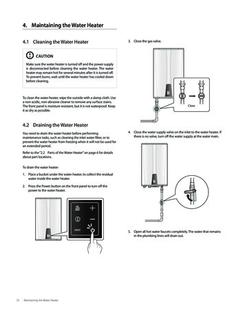
MAINTENANCEProperly maintained, your water heater can provide years of dependable,trouble free service. It is suggested that the purchaser follow the preventivemaintenance program outlined below.CONTROLSA periodic inspection of the operating controls, heating elements and wiringshould be made by qualified service personnel. Temperature of the water shouldbe tested periodically at the faucet to be sure thermostats are working properly.LONG TERM SHUT DOWNIf the water heater is to remain idle for an extended period of time, the powerand water to the heater should be turned off to conserve energy.The water heater and piping should be drained, if they might be subjected tofreezing temperatures.After a long shutdown period, qualified service personnel should check theheater’s operations and controls.Make certain the water is filled before placing it in operation.DRAINING THE HEATERCAUTION: Shut off all power to the heater before draining water. To drain thetank, a hot water faucet must be opened to admit air to the tank.1. Attach a hose to the drain valve on the heater.2. Close valve on the cold water line to the heater.3. Open the drain valve and direct the water to a drain.EMERGENCYShould the heater be subject to flood, fire or other damaging conditions, turnoff the power and water to the heater.DO NOT place water heater in operation again until it has been thoroughlychecked by qualified service personnel.11
WIRING DIAGRAMSTable 112
PARTS LIST1. Top Pan2. Relief Valve - Located above and to the left of hot water outlet.3. High Limit Safety Switch – Manual reset switch designed to shutoff all electrical circuits if water reaches the high limit setpoint.4. Electronic Control – For constant temperature control, temperaturecontrols are specifically designed for Hydrastone water heaters.Temperature sensors are located under access plates.5. Plastic Jacket – Durable & easy-to-clean jacket is hi density plastic.6. Water Diffuser – Introduces cold water at the bottom of the tank ina flat, gentle swirl, preventing turbulent mixing with heated waterabove. Tank drain is also a part of the cold water diffuser.7. Hot Water Outlet Nipple with Heat Trap8. Wiring & Connections – Located in front of the heater for easyinstallation and access.9. Long-Life Heating Elements – Waste is reduced with immersedheating elements because all available heat passes directly into thewater. Low watt density elements assure longer life – and reducemineral buildup.10.High-Density Insulation – Two inches of high-density foamblanket the storage tank. Extra thickness on top and bottomsignificantly reduce heat loss. (Three inches of insulation on M andME series)11.Bottom PanNOTE: When ordering parts, please specify model and serial number oftank, shown on the rating plate, as well as parts name, information andnumber.13
INSTALLATION DIAGRAM / PARTSLOCATIONFigure I14
VAUGHN ELECTRONIC TEMPERATURE CONTROLLEROPERATIONAbout the ControllerThe Vaughn Electronic Temperature Controller providesthe user with the ability to control and customize theoperation of their water heater. The 4-digit display showsthe current status of the water heater, and can display usefulinformation such as current temperature conditions insidethe tank, error notifications, and more. It allows basiccustomization, such as mode and temperature set point, aswell as more advanced options, such as temperaturedifferential, and display options. Once the setup is completethe water heater is automatic in operation and will maintaina full tank of water at the temperature setting of thecontroller.Powering up your Water Heater for the first timeWhen the unit is first powered up, the default home screen is shown. Thisscreen shows the temperature set point (e.g., 120).The Home ScreenThe home screen provides a quick reference to the current status of the waterheater, showing either the setpoint temperature or the actual temperatures atthe top and bottom of the tank, denoted by “t” and “b” preceding thetemperatures. The temperature readouts can be displayed in Fahrenheit orCelsius. There are power indicators to show which if any element should beon. These indicators blink when the element is heating properly.15
Button OverlayThe button overlay provides the user with a means to alter the configurationsettings and control the operation of the water heater. A brief description ofthe basic functionality of each button is provided below. Detaileddescriptions of how to use these buttons to perform certain functions isprovided throughout this manual.Power: Used for putting the water heater into standby mode,will be displayed. Used in the options menu to navigatebackwards. Used to cancel setpoint selection without saving.Mode: Used for navigating the options menu. Serves as a cancelbutton in certain menus.Up: Used for increasing numeric settings. Also scrolls up whenchanging options. Can be held for auto scroll.Down: Used for decreasing numeric settings. Also scrolls down whenchanging options. Can be held for auto scroll.Away: Used for entering / exiting vacation override. Also used to set/ unset child lock.(Vacation Override):Vacation mode deactivates the water heater for extended periods of time by overridingthe current mode the water heater is set to. This is useful for saving energy when thewater heater will not be used for a period of several days. The unit will maintain a watertemperature of 50 F to prevent freezing.To activate vacation override, press thebutton on the controller. The display willshow “A-07,” indicating the default vacation length of 7 days. The minimum vacationlength is 2 days and the maximum is 99 days. Use theorbuttons to adjust thedesired length of time to use vacation mode. The water heater will exit vacation modeautomatically one day before the specified time period has elapsed. It is designed thisway such that when the user returns from being away, hot water will be available.Once the desired time period is set, press thebutton to make the selection. The waterheater will now be in Vacation mode. The display will show “A-##”, where “##” is thenumber of days remaining in the vacation mode period.To manually cancel or end Vacation mode, press thebutton once.16
Child LockChild Lock is essentially a button locking mechanism. If the user wishes, he or she mayset the child lock, which will disrupt any future attempt to change modes, change the setpoint, etc. The user will be locked out of performing any function on the device until thechild lock is released.To activate the Child Lock feature, press and hold thebutton until “chLd” isdisplayed on the screen. The controller is now locked.To deactivate the child lock, press and hold thewill be returned to the home screen.button until “un” is displayed. YouController SettingsThe Vaughn Electronic Temperature Control is equipped with variouscustomizable options and settings. A brief overview of each option / settingis listed below:(Temperature Setpoint):The temperature setpoint represents the desired approximate temperature ofthe water inside the heater. The setpoint may be adjusted to your liking.There are pre-defined temperature limits to prevent extremely hot or freezingwater in the unit and surrounding piping.To change the temperature set point for hot water output, from the home screen, presstheANDbuttons on the controller. The display will flash the new temperatureset point as theorbuttons are pressed. Once the desired temperature setting hasbeen reached, allow the screen to time out after about 5 seconds. The new setpoint canalso be saved by pressing theANDbuttons. Pressingwill cancel the changeswithout saving. The display will now show the newly set temperature (e.g., “116”).17
To access the options menu, from the home screen, press and hold thebutton until the display reads “diFt” (top differential), this is the firstselection in the options menu.To navigate the options menu, continue to press thebutton to cyclethrough the available options until the desired option is displayed. When theoption to be changed is displayed, press theorbuttons to enter the editmode. When the display is flashing, the option may be altered by pressingtheorbuttons until the desired choice is displayed. To set the change,press thebutton, or press thebutton. The change will be made and thecontroller will return the user to the options menu. To exit the menu at anytime, let the display timeout after 5 seconds or press thebutton.18
(Diagnostics):Enabling this option causes the control to perform various checks, includingmaking sure each element works correctly. Any errors will be displayed afterall of the tests are complete.(Top Differential):(Bottom Differential):A temperature differential represents how far the water temperature can fallbefore the water heater must call for heat again. For example, if the setpointis 120 F and the differential is 10 F, then after satisfying at 120 F, the watertemperature must fall to 110 F before the water heater will call for heat.BuzzerThe buzzer is programmed to sound every 30 seconds whenever an error hasbeen detected. It is highly recommended that the user leave this buzzer on.However, this option allows the user to turn the buzzer off if desired.To turn the buzzer on or off, in the edit mode press theorbuttons toalternate between “On” and “OFF”.(Display):The display setting provides the ability to select whether the home shows thesetpoint temperature (diSS) or the measured water temperature (diSt) insidethe tank for the upper and lower sections. If “diSt” is selected, the homescreen will cycle the display to show the top temperature (designated by a ‘t’preceding the measurement) for 5 seconds, followed by the bottomtemperature (designated by a ‘b’ preceding the measurement) for 5 seconds.(Defaults):Enabling this option will reconfigure the controller to factory defaults. The factorydefaults are shown below.Top Differential: 30Bottom Differential: 10Buzzer: OnDisplay: Show Set PointDegrees: FahrenheitDisable Errors: All enabledTo set the unit back to factory defaults, in the edit mode press theorbuttons toalternate between cancelling the operation, “no”, or resetting to default, “YES”.19
(Degrees):The degrees option provides the user with the ability to switch betweenstandard and metric temperature readings. The “dEgF” choice will set thetemperatures to be displayed in Fahrenheit, and the “dEgC” choice will setthe temperatures to be displayed in Celsius.To change the display units, in the edit mode press theorbuttons toalternate between degrees Fahrenheit, “dEgF”, or degrees Celsius, “dEgC”.To set the change, let the display timeout after 5 seconds, press thebutton, or press thebutton.(Disable Errors):The disable errors option allows for the use of external timer controllers toinhibit operation of the elements during certain times without removingpower to the controller or otherwise affecting operation. The top and bottomelement errors can be chosen individually to be turned on or off. If noexternal control is used, these errors should remain enabled.Peak Demand Energy ControlVaughn has been designing and programming streamlined and sophisticatedenergy controllers in conjunction with electric utility thermal storageprograms for over 30 years, satisfying the utility's need for peak controlwhile also offering a great deal of flexibility for the end user. Programs forthe ETC are determined by the electric utility. Once programmed, the ETCautomatically controls the water heater, saving energy without any worry orinconvenience to the homeowner. If for some reason the homeowner wishesto override the system, an override may be accomplished with the simplepush of a button.During Peak Demand time periods, “P” will be displayed before the setpointtemperature. The controller could be programed with a customer overrideallowing the peak period to be temporally overridden for a predeterminedduration. If a customer override is available simply press the MODE buttonto allow full operation. “C” will be displayed while in override mode.Peak ModeCustomer Override20
TROUBLESHOOTINGCAUTION: Make certain power to heater is OFF before removing jacketaccess panel(s) for any reason.FOR QUALIFIED SERVICE PERSONNEL ONLY.ERROR CODESWhen the Vaughn Electronic Temperature Controller detects an abnormalcondition, the display will alternate between the home screen, ERR, and thenthe error code below.ERROR CODEPOSSIBLE CAUSEPOSSIBLE SERVICE REQ’DETC-H2O(Top or Bottom sensor)1. Temperature Sensor Issue2. Controller Sensing IssueF-01F-02(Top sensor)(Bottom sensor)F-03(Top Element)1. Temperature Sensor Issue2. Controller Sensing Issue*Replace or repair control1. Top Element Malfunction2. Controller Output Issue*Check wire connections*Replace or repair probes*Replace or repair control*Check wire connections*Replace or repair probesF-04(Bottom Element)1. Bottom element malfunction2. Controller output issueF-05(Both Elements)1. High limit tripped2. Controller output issue*Check wire connections*Replace top element*Replace or repair control*Check wire connections*Replace top element*Replace or repair control*Check high limit*Replace or repair controlNATURE OF TROUBLEPOSSIBLE CAUSEPOSSIBLE SERVICE REQ’DNo Hot Water1. Water Heater Switch turned off.2. Improper Wiring3. No Power—blown fusea. Circuit over loadb. Improper wiring4. Manual reset limit opena. Controller malfunctionb. Heat-up due to loose wires1. Heater undersized2. Element malfunction3. Controller malfunctionTurn ON*Check wiring diagram1. Control setting too high or low2. Control out of calibration3. Insulation around elementsnot properly replacedChange setting as requiredAdjust setting or replace**Replace insulation properlyNot enough Hot WaterWater too hot or too cool*Check wiring diagram*Provide adequate circuitAdjust setting or replace**Tighten connections*Install proper size heater*Replace element*Restore default settings*CAUTION: For your safety, DO NOT attempt repair of electrical wiring,thermostat(s), heating elements or other operating controls. Refer repairs to qualifiedservice personnel.21
HOW TO OBTAIN SERVICE ASSISTANCEVaughn Thermal Corporation does not have a service department or personnel toservice your heater in the field. A qualified installer or service technician must do allservice work. Therefore, if you have any questions about your new water heaterconcerning service adjustment, repair, routine maintenance, or replacement - firstcontact your installer, plumbing contractor or service agency.In the event that the contractor, for whatever reason, is unable to help, refer to thetelephone directory commercial listings for qualified service assistance.If neither action has solved your problem, contact Vaughn Thermal Corporation asfollows to obtain the number of a qualified service person in your area:CUSTOMER RELATIONS DEPARTMENTVAUGHN THERMAL CORPORATION26 OLD ELM STREETP.O BOX 5431SALISBURY, MA 01952Or call 978-462-6683When contacting Vaughn the following information should be made available:A. Model and serial number of the water heater as listed on insideback cover of this manual or on the rating plate on the heater.B. Address where water heater is installed.C. Name and address of dealer from whom the heater was purchased
the water heater. D. Feel water before bathing or showering. E. Temperature limiting valves are available, see manual. The temperature of the water in the heater is regulated by a Vaughn Electronic Temperature Controller with temperature sensors located behind the jacket access panels. These automatic controls are set at the factory to maintain .