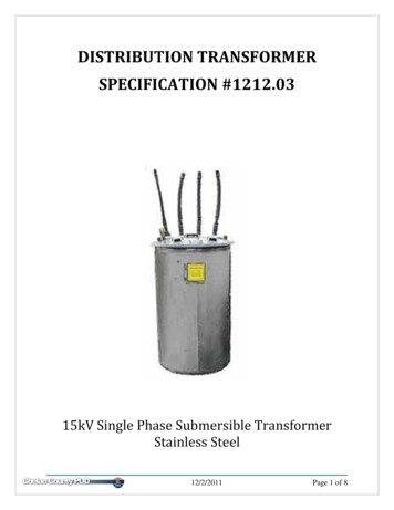
Transcription
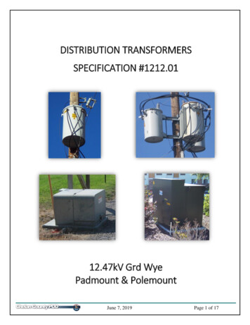
ENERGY STAR Product Specificationfor Distribution TransformersEligibility CriteriaFinal Draft Version 1.012Following is the Version 1.0 ENERGY STAR product specification for Distribution Transformers. Aproduct shall meet all of the identified criteria if it is to earn ENERGY STAR recognition.DEFINITIONS134A) Product Classifications:567891. Transformer: A device consisting of 2 or more coils of insulated conductor that transfersalternating current by electromagnetic induction from 1 coil to another to change theoriginal voltage or current value.Note: EPA has modified the definition of Transformer to mention "insulated conductor" instead of"insulated wire" to reflect different technologies available for conductor choice.102. Distribution Transformer: A transformer that:11a) Has an input voltage of 34.5 kV or less;12b) Has an output voltage of 600 V or less;13c) Is rated for operation at a frequency of 60 Hz; and1415d) Has a capacity of 10 kVA to 2500 kVA for liquid-immersed units and 15 kVA to2500 kVA for dry-type units.16e) The term “distribution transformer” does not include a transformer that is a(n)—17i.Autotransformer;18ii.Drive (isolation) transformer;19iii.Grounding transformer;20iv.Machine-tool (control) transformer;21v.Nonventilated transformer;22vi.Rectifier transformer;23vii.Regulating transformer;24viii.Sealed transformer;25ix.Special-impedance transformer;26x.Testing transformer;27xi.Transformer with tap range of 20 percent or more;28xii.Uninterruptible power supply transformer; or1Definitions are based on the U.S. Department Of Energy, "Energy Conservation Program for Certain Commercial and IndustrialEquipment: Distribution Transformers: Definitions", 10 CFR 431.192.ENERGY STAR Program Requirements for Distribution Transformers – Eligibility CriteriaPage 1 of 6
29xiii.30Welding transformer.B) Product Types:31321. Liquid-immersed Distribution Transformers: A distribution transformer in which the coreand coil assembly is immersed in an insulating liquid.332. Low-voltage Dry-Type Distribution Transformer: A distribution transformer that:34a) Has an input voltage of 600 volts or less;35b) Is air-cooled; and36c) Does not use oil as a coolant.3738393. Medium-voltage Dry-type Distribution Transformer: A distribution transformer in which thecore and coil assembly is immersed in a gaseous or dry-compound insulating medium,and which has a rated primary voltage between 601 V and 34.5 kV.40C) Operational Power States:41421. No-Load Loss (or Core Loss): Losses that are incident to the excitation of thetransformer at rated voltage.4344452. Load Loss (or Coil Loss): Losses that are incident to a specified load carried by thetransformer, including losses in the windings as well as stray losses in the conductingparts of the transformer.463. Total Loss: The sum of the no-load loss and load loss for a transformer.47Note: EPA has modified the definition of No-Load Loss to include "at rated voltage" for clarity.484950515253D) Basic Model: A group of models of distribution transformers manufactured by a singlemanufacturer, that have the same insulation type (i.e., liquid-immersed), have the same numberof phases (i.e., single or three), have the same standard kVA rating, and do not have anydifferentiating electrical, physical or functional features that affect energy consumption.Differences in voltage and differences in basic impulse insulation level (BIL) rating are examplesof differentiating electrical features that affect energy consumption.545556E) Per Unit Load: The ratio of the current through a transformer’s output winding multiplied by thenameplate voltage and divided by the capacity, at unity power factor and zero input voltagedistortion.5758F) Load Factor: The ratio of the average load over a period of time to the peak load during thattime.25960G) Basic Impulse Level (BIL): Refers to the level of insulation wound into a transformer, dictating itsdesign voltage3.6162Note: EPA has added a definition for Basic Impulse Level (BIL) to inform the scope exclusion of productswith a BIL greater than 150 kV.2IEEE PC57.120/D16.1 Loss Evaluation Guide for Distribution and Power Transformers and Reactors, March 2013, 18.U.S. Department Of Energy, "2012-02-03 Technical Support Document", https://www.regulations.gov/document?D EERE-2010BT-STD-0048-0104.3ENERGY STAR Program Requirements for Distribution Transformers – Eligibility CriteriaPage 2 of 6
SCOPE63642.1Included Products65662.1.1Products that meet the definition of Liquid-Immersed Distribution Transformers are eligible forENERGY STAR certification.672.2Excluded Products6869702.2.1Products that are covered under other ENERGY STAR product specifications are not eligible forcertification under this specification. The list of specifications currently in effect can be found atwww.energystar.gov/specifications.712.2.2The following products are not eligible for certification under this specification:72i.The following types of Liquid-Immersed Distribution Transformers:73(1) Single-phase with capacity greater than 500 kVA;74(2) Three-phase transformers intended for a vault application; and75(3) All transformers with a BIL 150 kV.76ii.77iii. Medium-voltage Dry-type Distribution Transformer.78798081828384Low-voltage Dry-Type Distribution Transformer; andNote: EPA has excluded single-phase transformers larger than 500 kVA, three-phase vault transformers,and all transformers with a BIL greater than 150 kV due to a lack of data on appropriate efficiency criteria.In its call for data from stakeholders, EPA did not receive any data on products that would be able to meetefficiency criteria beyond the DOE specification. Since these types of transformers represent a low marketshare, excluding them will likely not significantly impact energy savings potential. EPA will continue tomonitor the market to determine the feasibility of and energy savings opportunity for including these typesof products within the scope of the specification in a future revision.CERTIFICATION CRITERIA85863.1Significant Digits and Rounding87883.1.1All calculations shall be carried out with actual measured (unrounded) values. Only the final resultof a calculation shall be rounded.89903.1.2Unless otherwise specified, compliance with specification limits shall be evaluated using exactvalues without any benefit from rounding.9192933.1.3Directly measured or calculated values that are submitted for reporting on the ENERGY STARwebsite shall be rounded to the nearest significant digit as expressed in the correspondingspecification limit.ENERGY STAR Program Requirements for Distribution Transformers – Eligibility CriteriaPage 3 of 6
943.2Total Owning Cost95969798993.2.1Manufacturers are encouraged to highlight for purchasers the total owning cost savings over thelifetime of the product, based on a utility’s no-load and load loss evaluation factors. Manufacturersshould calculate the total owning cost savings taking into account the utility’s A (no-load) and B(load) loss evaluation factors and comparing them to that for the manufacturer’s design that justcomplies with Federal standards.100i.TOC shall be calculated per Equation 1.4101Equation 1: Total Owning Cost102𝑇𝑂𝐶 𝑃 𝐴 𝑁𝐿 𝐵 𝐿𝐿85 𝐶103Where: 104105106107108109110111 TOC is the Total Owning Cost;P is the bid price in dollars (USD);A is the utility’s equivalent first cost of no-load losses, in dollars per watt;NL is the no-load loss power corrected for wave-form distortion and then to the referencetemperature of 20 C, in watts;B is the utility’s equivalent first cost of load losses, in dollars per watt; andLL85 C is the load loss power corrected to the reference temperature of 85 C and incorporatingohmic and stray losses, in watts.1123.3Energy Savings at Optimized Load Factor1131141153.3.1The Percentage Energy Savings over the minimum DOE-compliant Design, calculated perEquation 2, shall be greater than or equal to the requirement specified in Table 1, subject to thefollowing requirements.116117118i.A model meeting the requirements at one of the load factors can become ENERGY STARcertified for that specific load factor. The model will thus need to be marketed as certified onlyfor use at the load factors where it meets the requirements in Table 1.119120ii.For models with multiple ratings, each portion of the transformer shall meet the criteriaapplicable to the portion’s kVA rating.121122Note: EPA has issued a clarification to the specification that transformers with multiple ratings and duplextransformers shall have each portion of the unit meet the criteria applicable to the portion’s kVA rating.123Equation 2: Percentage Energy Savings over Minimum DOE-compliant Design𝑆𝑎𝑣𝑖𝑛𝑔𝑠 124125(𝐿𝐿𝐷𝑂𝐸 𝐿2 𝑁𝐿𝐷𝑂𝐸 ) (𝐿𝐿 𝑇𝑂𝐶 𝐿2 𝑁𝐿 𝑇𝑂𝐶 ) 100%𝐿𝐿𝐷𝑂𝐸 𝐿2 𝑁𝐿𝐷𝑂𝐸Where:126127 𝑆𝑎𝑣𝑖𝑛𝑔𝑠 is the Percentage Energy Savings over the minimum DOE-compliant design at theutility-specified load factor;128 𝑁𝐿𝐷𝑂𝐸 129130131 DOE minimum efficiency specified in 10 CFR 431.196(b)(2) as a decimal;LLDOE 4 NLDOEL is the load factor at which the losses are evaluated, with 100% load factor equal to capacity.4𝑘𝑉𝐴4 (1 �� ��� 1000, where kVA is the capacity and, EfficiencyDOE is theIEEE PC57.120/D16.1 Loss Evaluation Guide for Distribution and Power Transformers and Reactors, October 2016, 5.ENERGY STAR Program Requirements for Distribution Transformers – Eligibility CriteriaPage 4 of 6
132133134135 LLTOC is the full load winding loss power of the TOC-optimized design corrected to the referencetemperature of 55 C and incorporating ohmic and stray losses; andNLTOC is the no-load loss power of the TOC-optimized design corrected for wave-form distortionand then to the reference temperature of 20 C.136137138139Note: EPA updated Equation 2 with the assumption that the minimum DOE designs will have a core lossequal to load loss at the 50% load factor. This approach will reduce burden for manufacturers by keepingthe performance of the DOE model a constant for a given capacity for all manufacturers, rather than avariable that would need to be modeled for each TOC-optimized design.140Table 1: Minimum Percent Energy Saving at Operating Load FactorsRange of Utility Specified Load Factors:Specific Load Factor at whichRequirements Must be Met: 30%30–40% 40–55% 55%25%35%50%65% DesignLineNumberofPhasesTank ShapeCapacityRange(kVA)11Rectangular 16725%12%11%21%21Round 16725%12%14%25%31Round 16725%12%20%27%43Rectangular 50025%12%19%29%53Rectangular 50025%12%16%16%Percentage Energy Savings over Minimum DOEcompliant Design (%)141142143144145Note: EPA has maintained the requirements for the load factor ranges that were presented in Draft 2, butdivided the high load factor bin into two: 40–55% and 55% (in Draft 2, the highest bin included loadfactors 40%). EPA made this modification based on stakeholder feedback requesting a specific load bingreater than 40% and subsequently found that having a higher load bin will also generate more energysavings.146147148149150151152In addition, EPA has provided energy savings requirements for Design Lines (DLs) 3 and 5 at the lowerload factor bins. These were marked as TBD in the Draft 2 specification due to concerns with additionalcore weight required to meet the same requirements as the other design lines, especially for DL 3. EPArequested data from stakeholders but did not receive any. Instead, EPA performed its own analysis andfound that meeting the requirements would increase weight by 11% if using M3 steel and not increase itat all if using DR80. Due to these modest increases, EPA is proposing the same requirements as for theother Design Lines.153154155156157158159160161162163164Finally, EPA received feedback that optimizing transformers at each utility-provided load factor within abin would be burdensome for manufacturers. To reduce burden, EPA has provided specific load factors inthe midpoint of each bin at which the requirement shall be met. Based on analysis, EPA does not expectthis to decrease savings significantly. The midpoint was chosen by reviewing the RMS load distributionfor DL 1 previously developed by DOE. Designating one load factor within a bin should simplify theprocess of providing ENERGY STAR designs in response to a customer request. A manufacturer will beable to provide just a single ENERGY STAR design that is acceptable across the entire load factor bin,rather than ensuring that its designs meet the requirements each time a utility purchaser provides a loadfactor. For example, if a utility requests a transformer for a load factor of 39%, the manufacturer wouldonly have to ensure that its proposed designs provide 12% savings over the minimum DOE compliantdesign at 35% rather than at 39%. This same design could also be provided to a subsequent request at32% load factor.ENERGY STAR Program Requirements for Distribution Transformers – Eligibility CriteriaPage 5 of 6
TESTING1651664.1Test Methods1674.1.1Test methods identified in Table 2 shall be used to determine certification for ENERGY STAR.168Table 2: Test Methods for ENERGY STAR CertificationProduct TypeAllTest MethodU.S. Department of Energy, "Test procedures for measuringenergy consumption of distribution transformers", Appendix A toSubpart K of 10 CFR Part 4311694.2Number of Units Required for Testing1704.2.1Basic Model shall be selected for testing per the requirements in the Department of Energy171Certification Requirements for Distribution Transformers, 10 CFR 429.47.172173i.For certification of an individual product model, the Basic Model shall be the model which isintended to be marketed and labeled as ENERGY STAR.174175176ii.For certification of multiple product models under the Basic Model definition, the AlternativeEfficiency Determination Method (AEDM) may be used to certify all subsequent models thatmeet the Basic Model parameters.177178179180181182183Note: EPA will allow transformer manufacturers to follow the same laboratory testing procedures whencertifying a product to ENERGY STAR as they do when reporting their product performance to DOE. Assuch, manufacturers will be able to use both the same actual test results submitted to DOE as well asmodeled results from the same alternative efficiency determination method (AEDM) they currently use todemonstrate DOE compliance, allowing for more timely response to potential customers regardingENERGY STAR status of design options.EFFECTIVE DATE1841851861875.1.1Effective Date: The Version 1.0 ENERGY STAR Distribution Transformers specification shall takeeffect on TBD. To certify for ENERGY STAR, a product model shall meet the ENERGY STARspecification in effect on the model’s date of manufacture. The date of manufacture is specific toeach unit and is the date on which a unit is considered to be completely assembled.1881891901911925.1.2Future Specification Revisions: EPA reserves the right to change this specification shouldtechnological and/or market changes affect its usefulness to consumers, industry, or theenvironment. In keeping with current policy, revisions to the specification are arrived at throughstakeholder discussions. In the event of a specification revision, please note that the ENERGYSTAR certification is not automatically granted for the life of a product model.ENERGY STAR Program Requirements for Distribution Transformers – Eligibility CriteriaPage 6 of 6
42 transformer at rated voltage. 43 2. Load Loss (or Coil Loss): Losses that are incident to a specified load carried by the 44 transformer, including losses in the windings as well as stray losses in the conducting 45 parts of the transformer. 46 3. Total Loss: The sum of the no-lo