Transcription
90 GAS FURNACE INSTALLATION INSTRUCTIONSTable of ContentsGAS FURNACE SAFETY.1INSTALLATION REQUIREMENTS .3Tools and Parts .3Location Requirements.3Installation Configurations .4Duct Work Requirements.5Electrical Requirements .5Gas Supply Requirements .5Venting Requirements.5INSTALLATION INSTRUCTIONS .6Inspect Shipment .6Plan Vent System .7Determine Vent Pipe Direction.9Connect Venting.14Install Condensate Disposal.14Install Duct Work .15Filter Specifications .15Make Electrical Connections .16Make Gas Connections.17Check the Furnace Input Rate .17Adjust the Furnace Input Rate .18Complete Installation.19Sequence of Operation .20Controls .20TROUBLESHOOTING .21ASSISTANCE OR SERVICE .24Accessories .24GAS FURNACE SAFETYYour safety and the safety of others are very important.We have provided many important safety messages in this manual and on your appliance. Always read and obey allsafety messages.This is the safety alert symbol.This symbol alerts you to potential hazards that can kill or hurt you and others.All safety messages will follow the safety alert symbol and either the word “DANGER” or“WARNING.” These words mean:You can be killed or seriously injured if you don'timmediately follow instructions.You can be killed or seriously injured if you don'tfollow instructions.All safety messages will tell you what the potential hazard is, tell you how to reduce the chance of injury, and tell youwhat can happen if the instructions are not followed.Models WFCU, WFCC, WGFDC, WGFDU46948D003Whirlpool Home Cooling and Heating7901 S.W. 6th CourtPlantation, Florida 33324
IMPORTANT SAFETY INSTRUCTIONS Use only with type of gas approved for this furnace.Refer to the furnace rating plate.Install this furnace only in a location and positionas specified in the Location Requirements sectionof these instructions. Provide adequate combustion and ventilation air tothe furnace space as specified in the “VentingRequirements” section of these instructions.When a furnace is installed so that supply ductscarry air circulated by the furnace to areas outsidethe space containing the furnace, the return airshall also be handled by duct(s) sealed to thefurnace casing and terminating outside the spacecontaining the furnace. Combustion products must be discharged outdoors.Connect this furnace to an approved vent systemonly, as specified in the “Venting Requirements”section of these instructions. A gas-fired furnace for installation in a residentialgarage must be installed as specified in the“Location Requirements” section of theseinstructions.The furnace is not to be used for temporary heatingof buildings or structures under construction.Never test for gas leaks with an open flame. Use acommercially available soap solution made specifically for the detection of leaks to check all connections, as specified in the “Make Gas Connections”section of these instructions.Adequate clearance must be provided around thevent-air intake terminals.Always install furnace to operate within the furnace’sintended temperature-rise range with a duct systemwhich has an external static pressure within theallowable range, as specified in the “CompleteInstallation” section of these instructions. Seefurnace rating plate. The furnace shall be installed so the electricalcomponents are protected from water. Furnaces for indoor installation on combustibleflooring shall not be installed directly on carpeting,tile or other combustible material other than woodflooring.SAVE THESE INSTRUCTIONSThe California Safe Drinking Water and Toxic Enforcement Act requires the Governor of California to publish a listof substances known to the State of California to cause cancer, birth defects, or other reproductive harm, andrequires businesses to warn of potential exposure to such substances.WARNING: This product contains a chemical known to the State of California to cause cancer, birth defects, orother reproductive harm.This appliance can cause low-level exposure to some of the substances listed, including benzene, formaldehyde,carbon monoxide, toluene, and soot.ADDITIONAL SAFETY INFORMATIONIn the State of Massachusetts, the following installation instructions apply: 2Installations and repairs must be performed by a qualified or licensed contractor, plumber, or gasfitter qualified orlicensed by the State of Massachusetts.If using a ball valve, it shall be a T-handle type.A flexible gas connector, when used, must not exceed 3 feet.
Location RequirementsINSTALLATIONREQUIREMENTSThese instructions are intended as a general guide only for use byqualified persons and do not supersede any national or localcodes in any way. Compliance with all local, state, or nationalcodes pertaining to this type of equipment should be determinedprior to installation.Read this entire instruction manual, as well as the instructionssupplied in separate equipment, before starting the installation.The installation of the furnace, wiring, warm air ducts, venting,etc. must conform to the requirements of the National FireProtection Association; the National Fuel Gas Code, ANSIZ223.1/NFPA No. 54 (latest edition) and the National ElectricalCode, ANSI/NFPA No. 70 (latest edition) in the United States, andany state laws, local ordinances (including plumbing orwastewater codes), or local gas utility requirements. Localauthorities having jurisdiction should be consulted beforeinstallation is made. Such applicable regulations or requirementstake precedence over the general instructions in this manual.This furnace design is certified by CSA International as aCategory IV furnace in compliance with the latest edition ofAmerican National Standard Z21.47/CSA Standard 2.3 for GasFired Central Furnaces, for operation with natural gas or propane.Consult the rating plate on the furnace for gas type beforeinstalling.Explosion HazardKeep flammable materials and vapors, such asgasoline, away from furnace.Place furnace so that burners are at least 18 inches(46 cm) above the floor for a garage installation.Failure to follow these instructions can result in death,explosion, or fire.Tools and PartsAssemble the required tools before starting installation. Read andfollow the instructions provided with any tools listed here.Tools Needed: Pipe wrench Non-corrosive leak check solution Screwdriver Tape measureTest gauge with ¹ ₈ in. NPTconnection(for measuring gas supply pressure) Thread sealantParts Needed:Check local codes and with gas supplier. Check existing gassupply, electrical supply, and venting, and read “Duct WorkRequirements,” “Electrical Requirements,” “Gas SupplyRequirements” and “Venting Requirements” before purchasingparts.Parts Supplied Inlet air restrictor plate Flue pipe screenExplosion HazardDo not install this furnace in a mobile home.Doing so can result in death, explosion, fire, orcarbon monoxide poisoning.IMPORTANT: Do not use the furnace as a heater in a buildingunder construction. The furnace can be severely damaged due tothe abnormal environment caused by construction. Chloridesfrom sources such as paint, stain, or varnish; tile and countercements; adhesives; and foam insulation are abundant in astructure under construction and can be highly corrosive. Lowreturn air temperature can cause condensation in the furnace andother damage that can shorten the life of the furnace. The condensate drain on this furnace is incorporated withinthe furnace and must be primed before start-up. Thecondensate system must not be exposed to temperaturesunder 32 F. The furnace is suitable for installation in buildingsconstructed on site. The furnace should be centralized inrespect to the heat distribution system as much aspracticable.3
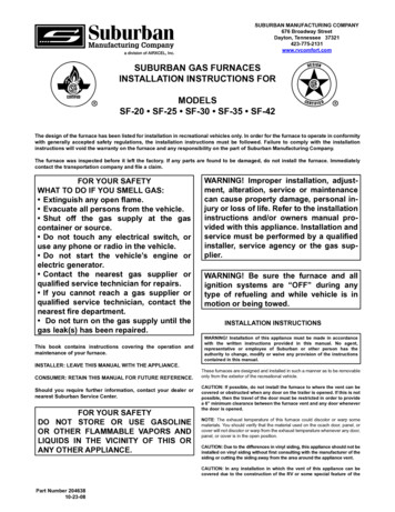
All models are suitable for closet or utility room installation.Utility room installation requires:A door opening large enough for the widest part of thefurnace.A door opening large enough to remove/replace any otherappliance located in the utility room, such as a water heater.Any other appliances arranged so that each appliance can beremoved/replaced without disturbing the furnace. In a residential garage, a gas-fired furnace must be installedso the burner(s) and the ignition source are located not lessthan 18 in. above the floor. The furnace is to be located orprotected to avoid physical damage by vehicles.Installation ConfigurationsWGFDU and WFCU models must be installed only as upflowfurnaces.WGFDC and WFCC models must be installed only ascounterflow (downflow) furnaces.IMPORTANT: To ensure access to parts for servicing, installupflow and counterflow furnaces so that the burner and bloweraccess panels are readily accessible.Installation for Counterflow (Downflow) ModelsIf the furnace is to be installed in an attic or other insulatedspace, it must be kept free and clear of insulating materials.WARNINGInstallation Clearances A 2 in. minimum clearance is required in front for air openingsinto the combustion chamber. All servicing and cleaning of the furnace can be performedfrom the front. If installed in a closet or utility room, provide 24in. clearance in front for service if the door to the room is notin line with the front of the furnace. Where servicingclearances are greater than clearances to combustibles,servicing clearances take precedence.Fire HazardBefore installing counterflow (downflow) furnace oncombustible surface, such as wood, install one of thefollowing kits:Minimum Clearance to Combustibles ChartUnit Sides0"Rear of Unit0"WABASE 511 (14.5" cabinets)WABASE 512 (17.5" cabinets)WABASE 568 (21" cabinets)WABASE 569 (24.5" cabinets)Front of Unit2"Contact your local dealer.Flue Pipe0"Plenum Top (upflow)1"Supply Duct (counterflow)1"Failure to do so can result in death or fire.IMPORTANT: The furnace may be installed directly on the supply plenum orcoil cabinet if the furnace is installed on a non-combustiblefloor. High Altitude Installations This furnace is approved for operation at altitudes from 0 to4,500 feet above sea level without any required modifications. From 4,500 to 7,500 ft, the gas manifold pressure needs to beadjusted according to the information shown in the ManifoldPressure vs. Altitude charts.IMPORTANT:For installations above 7,500 ft, the furnace input rate is to bereduced per the requirements of the National Fuel Gas Code(ANSI Z223.1/NFPA 54, latest edition), at the rate of 4 percent foreach 1,000 feet above sea level.The furnace is not recommended for installation above 10,000 ft.4For installations on combustible flooring, a special base mustbe ordered and used. See the “Accessories” section.1. Cut, size and frame opening in floor to fit the Combustiblefloor base and provide a minimum 1 in. clearance betweenthe Supply Duct and combustible materials. The four legs onthe base assembly should recess into the floor and the baseshould rest on all four outside flanges.2. Construct duct connections with 1 in. to 1³ ₄ in. right angleflanges, and long enough to extend below the floor joists.3. Drop the duct connections through the top of the baseassembly with the right angle flanges in good contact withthe glass tape on top of the base assembly.4. Carefully position the furnace over the right angle ductflanges.
Combustible Floor Installation (Counterflow Models only)1 In all instances, other than wiring for the thermostat, thewiring to be done and any replacement of wire shall conformwith the temperature limitation for Type T wire – 63 F (35 C)rise. The line voltage supply should be routed through a readilyaccessible disconnect located within sight of the furnace. Ajunction box on the furnace side panel is provided for linevoltage connections. See the furnace wiring diagram forspecific connection information. Proper polarity of the supply connections (“HOT” and“NEUTRAL”) must be observed to ensure that safety controlsprovide the protection intended.23456Gas Supply RequirementsThis furnace is equipped for use with natural gas. A conversionkit is required for use with propane. To order the correctconversion kit, see “Accessories.” Gas supply piping should be installed in accordance withlocal codes and the regulations of the utility. Piping must beof adequate size to prevent undue pressure drop. Consult thelocal utility or gas supplier for complete details on specialrequirements for sizing gas piping. 1. Furnace2. Woven glass tape (betweenflanges of outlet duct andbase assembly)3. Base assembly4. Combustible flooring5. Leg6. Supply plenum or coil cabinet(not provided - accessory)Duct Work RequirementsInstall the conditioned air plenum, ducts and air filters (if notprovided on the furnace) in accordance with NFPA 90B Standardfor the Installation of Warm Air Heating and Air-ConditioningSystems (latest edition).The furnace is provided with flanges for the connection of theplenum and ducts.All air filters must be listed as Class 2 furnace air filters.Electrical RequirementsWARNINGIf local codes allow the use of a flexible gas applianceconnector, always use a new listed connector. Do not use aconnector which has previously serviced another gasappliance.Venting RequirementsAdequate provisions for combustion air and ventilation of furnacemust be made. Refer to Section 5.3, “Air for Combustion andVentilation,” of the National Fuel Gas Code, ANSI Z223.1/NFPA54(latest edition), or applicable provisions of the local buildingcodes.Unconfined SpaceAn unconfined space is defined as “a space whose volume ismore than 50 cubic feet per 1000 BTU per hour of the combinedinput rating of all appliances installed in that space.”When a furnace is installed in an unconfined space in a building,it can be assumed that the infiltration will be sufficient to supplythe required air.If the furnace is installed in a ventilated attic or crawl space, it isassumed that the air infiltration is sufficient to supply the requiredcombustion air. However, in a building of unusually tightconstruction, additional outdoor air should be provided.Confined SpaceA confined space is defined as “a space whose volume is lessthan 50 cubic feet per 1000 BTU per hour of the combined inputrating of all appliances installed in that space.” Use Direct Ventmethod. See “Plan Ventilation System.”Electrical Shock HazardElectrically ground furnace.Connect ground wire to green ground screw.Failure to do so can result in death or electrical shock. The furnace must be grounded and wired in accordance withlocal codes or, in the absence of local codes, with theNational Electrical Code ANSI/NFPA No. 70 (latest edition).5
Contaminated Combustion AirINSTALLATIONINSTRUCTIONSExcessive exposure to contaminated combustion air will result inperformance related problems. The recommended source ofcombustion air is outdoor air.Outdoor air as the source of combustion airIf the furnace is installed in a confined space, it is recommendedthat the necessary combustion air come from the outdoors byway of an attic, crawl space, air duct, or direct opening.Outdoor air is required as the source of combustion air when theindoor air is contaminated with chemical substances and in thefollowing types of installations: Furnaces installed in commercial buildings Furnaces installed in buildings with indoor pools Furnaces installed in hobby or craft rooms Furnaces installed near chemical storage areas Furnaces installed in laundry roomsFurnace must be installed and serviced by aqualified person. Furnaces installed in hair salonsExamples of a qualified person include:Explosion HazardIndoor air as the source of combustion airIndoor air as the source of combustion air is acceptable in mostapplications if the following guidelines are met: All provisions for indoor combustion air must meet therequirements for combustion air indicated in the National FuelGas Code, ANSI Z223.1/NFPA 54 (latest edition), and/or anyapplicable local codes. licensed heating personnel,authorized gas company personnel.Read and follow all instructions provided forinstallation, adjustment, service, alteration, ormaintenance.Failure to follow these instructions can result in death,explosion, fire, or carbon monoxide poisoning.If indoor combustion air is used, the air supply to the furnaceshould not be exposed to the following substances:Permanent wave solutionsInspect ShipmentChlorinated waxes and cleanersChlorine-based swimming pool chemicalsWARNINGWater softening chemicalsDeicing salts or chemicalsExcessive Weight HazardCarbon tetrachlorideUse two or more people to move and install furnace.Halogen-type refrigerantsFailure to do so can result in back or other injury.Cleaning solvents (such as perchloroethylene)Printing inks, paint removers, varnishes, etc.Masonry acid washing materialsThis furnace is shipped in one package, completely assembledand wired. The thermostat is shipped in a separate carton whenordered. Check the unit rating plate to confirm specifications are asordered.Chlorinated laundry products Upon receipt of equipment, carefully inspect it for possibleshipping damage. Take special care to examine the unitinside the carton if the carton is damaged. If damage is found, it should be noted on the carrier’s freightbill. Damage claims should be filed with the carrierimmediately. Claims of shortages should be filed with theseller within 5 days.Cements and gluesAntistatic fabric softeners for clothes dryersHydrochloric acidNOTE: If any damages are discovered and reported to thecarrier, do not install the unit, as your claim may be denied.6
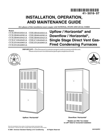
Plan Vent SystemThe high efficiency of this furnace is accomplished by theremoval of both sensible and latent heat from the flue gases. Theremoval of latent heat results in the condensation of moisture inthe flue gases. This condensation occurs in the secondary heatexchanger and in the vent system. Therefore, this furnacerequires special venting considerations and the instructions mustbe followed to ensure proper operation. All venting must be inaccordance with the codes having jurisdiction in the area andthese instructions.IMPORTANT: The venting system must be supported with mounting strapsto prevent any weight load from being applied to the ventblower. Horizontal vent pipe must be supported every 5 ft andvertical pipe should be supported every 10 ft to preventsagging and provide rigid support. This furnace must not be connected to any Type B, BW, or Lvent or vent connector and must not be connected to anyportion of a factory-built or masonry chimney. This furnace is not to be common vented with any otherappliance. The vent pipe must not be connected to achimney flue serving a separate appliance designed to burnsolid fuel.Venting OptionsWFCU, WFCC, WGFDC and WGFDU models can be installed aseither direct vent or non-direct vent units.For either type of installation, special venting considerationsmust be followed. See “Determine Vent Pipe Direction” sectionfor the type of furnace and venting being installed.Direct VentA direct vent (two pipe) installation requires that all the airnecessary for combustion be supplied from outside the dwellingthrough an air intake pipe. All vents passing through floors, ceilings, and walls must beinstalled in accordance with National Fuel Gas Code, ANSIZ223.1/NFPA 54 (latest edition). In all applications where theflue pipe is run through an unconditioned space, ¹ ₂ in.insulation must be used over the pipe. In extremely coldclimates, ³ ₄ in. insulation is recommended.Non-Direct VentA non-direct vent (one pipe) installation uses air from inside thedwelling for combustion. The furnace is shipped with the air inlet pipe terminated to thetop panel for either inside or outside combustion air. An inletair restrictor plate is supplied with this furnace and can befound in the plastic bag containing these InstallationInstructions and the User’s Information Manual. For installations using inside air for combustion (non-directvent), attach a 90 elbow (not supplied) to the inlet couplerand install the restrictor plate inside the elbow (see “NonDirect Vent Installation”).Inlet Air Restrictor PlateThe inlet air restrictor platemust be installed in allinstallations using inside airfor combustion (non-directvent).Flue Pipe ScreenA flue pipe screen designed to keep objects out of the flue pipe isincluded in the plastic bag.In all installations, this screen should be installed at thetermination of the flue pipe.Flue Pipe ScreenThe flue pipe screenshould be installed at thetermination of the flue pipein all installations.7
Materials Vent Pipe Size and LengthAll pipe, fittings, primer, and solvent cement must conformwith American National Standard Institute and the AmericanSociety for Testing and Materials (ANSI/ASTM) standards.The solvent shall be free flowing and contain no lumps,undissolved particles, or any foreign matter that adverselyaffects the joint strength or chemical resistance of thecement. The cement shall show no gelatinization,stratification, or separation that cannot be removed bystirring. See “Piping and Fitting Specifications” for approvedpiping and fitting materials.Piping and Fitting Specifications Piping and Fitting MaterialASTM SpecificationSchedule 40 PVC (Pipe)D1785Schedule 40 PVC (Cellular Core Pipe)F891Schedule 40 PVC (Fittings)D2466SDR-26 (Pipe)D2241Schedule 40 ABS (Pipe)D1527Schedule 40 ABS (Fittings)D2468Schedule 40 & 80 CPVC (Pipe)F441ABS-DWV Drain Waste & Vent(Pipe & Fittings)D2661PVC-DWV Drain Waste & Vent(Pipe & Fittings)D2665The primers and solvents used must also meet ASTMspecifications. PVC primer is specified in ASTM F656. UsePVC solvent as specified in ASTM D2564 and ABS solventcement as specified ASTM D2235. Low temperature solventcement is recommended. Metal or plastic strapping may beused for vent pipe hangers.When making ABS joints, pieces can be prepared with acleaner. When joining ABS to PVC materials, use PVC solventcement as specified in ASTM D3138.Preferred fittings are DWV style or long sweep. Seal all jointsgas tight with appropriate cement. In areas where vent and airintake pipes are exposed to abnormal stress or are subject todamage, schedule 80 pipe should be used.Use high temperature RTV silicone sealant to attach the airintake pipe into the connector on the burner box so the airintake pipe can be removed if service is required.The vent pipe and air intake pipe (in direct vent installations)should be sized in accordance with the information found in the“Vent Tables.” One 90 elbow is equivalent to 5 ft of pipe.Two 45 elbows are equivalent to one 90 elbow.The minimum lengthcertified for use with this furnace is 5 ft and one elbow, notincluding the vent and air intake terminals.Vent Table - 40,000 - 80,000 BTU/HR ModelsVent PipeLength (ft)Minimum Pipe Diameter (in.)51.5 2222250226022.5 2.5 2.52.5 2.5 2.5 2.5 2.52.5 2.5 2.5 2.5 2.5 2.5 2.5 NR2.5 2.5 2.5 2.5 2.5 2.5 NR NR NR702.5 2.5 2.5 2.5 2.5 NR NR NR NR NR802.5 2.5 2.5 NR NR NR NR NR NR NR902.5 2.5 NR NR NR NR NR NR NR NRNumber of 90 Elbows0123456789NR Not RecommendedVent Table- 90,000 - 100,000 BTU/HR ModelsVent PipeLength (ft)Minimum Pipe Diameter (in.)5NR2222210222222202222230222402222.5 2.5 2.5 2.52.5 2.5 2.5 2.52.5 2.5 2.5 2.52.5 2.5 2.52.5 2.5 2.533333333333NR502.5 2.5 2.53333602.53333337033333803339033Number of 90 Elbows01NOTE: Do not use cement.NR Not Recommended8NR NR NRNR NR NR NR NRNR NR NR NR NR NR NRNR NR NR NR NR NR NR NR23456789
Vent Table - 112,000 - 125,000 BTU/HR ModelsVent PipeLength (ft)Minimum Pipe Diameter (in.)52.5 2.5 2.5 2.5 2.5 2.5 2.5 2.5 2.5 2.5102.5 2.5 2.5 2.5 2.5 2.5 2.5 2.5 2.5202.5 2.5 2.5 2.5 2.5 2.5 2.5302.5 2.5 2.5 2.5 2.5402.5 2.5 2.5 2.5502.536033Number of 90 Elbows013333333NRNR NR NRIn the event that the pipe length is in between the lengths listed inthe Vent Table, use the next larger length listed. For example, if alength of pipe needed to install the furnace is 27 ft, use thediameter values for the 30 ft row in the tables.For direct vent installations, if the vent and air intake pipe are notequal in length and number of elbows, then determine theminimum pipe diameter for both the vent and air intake. If theresults indicate different diameters, use the larger of the two forboth the vent and air intake.NOTE: Under no circumstances should the vent and air intakepipe size be different in diameter. See “Install Vent System” forthe unit model and type of installation.NR NR NR NR NRNR NR NR NR NR NR NRNR NR NR NR NR NR NR NR23456789NR Not RecommendedDetermine Vent Pipe DirectionThe vent system of the furnace must be self-supporting and must not apply any weight load to the combustion blower.Combustion Air SourcesThere are 2 sources for combustion air:1. From outside the building (Direct Vent)2. From inside the building (Non-Direct Vent)Please read the information provided here about Vertical andHorizontal Venting, then find and follow the instructions for yourventing configuration.Vertical VentingA vertical vent should extend through the roof a minimum of 2 ftand not be obstructed a minimum of 10 ft in any direction.Horizontal VentingThe vent terminal location shall comply with Section 7.8 of theNational Fuel Gas Code (ANSI Z223.1) or local requirement,whichever takes precedence. For informational purposes, theapplicable sections of Section 7.8 are reprinted here:The venting system shall terminate at least 3 feet (0.9 m)above any forced air inlet located within 10 feet (3.1 m).Thisprovision shall not apply to the combustion air inlet of a directvent appliance or to the separation of the circulating air inletand vent discharge of a listed outdoor appliance.For non-direct vent installation, the vent system shallterminate at least 4 feet (1.2 m) below, 4 feet (1.2 m)horizontally from, or 12 inches (30 cm) above any door,window, or gravity inlet into any building.The bottom of thevent terminal shall be located at least 12 inches (30 cm)above grade or maximum expected snow depth.For direct vent installation of models with an input rating of50,000 BTUH or less, the vent system shall terminate at least9 inches (23 cm) from any opening through which flue gasescould enter a building. For direct vent installation of modelswith an input greater than 50,000 BTUH, the vent systemshall terminate at least 12 inches (30 cm) from any openingthrough which flue gases could enter a building.Regardless of input, the vent terminal and air intake shallterminate at least 12 inches (30 cm) above grade or maximumexpected snow depth.The vent system, regardless of installation type, shallterminate a minimum horizontal clearance of 4 ft from electricmeters, gas meters, regulators, and relief equipment.9
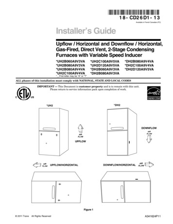
Direct Vent Installation Upflow ModelsRefer to the appropriate vent table for proper pipe size, ventlength and the number of elbows allowed, and air intakelength and the number of elbows allowed. Refer to the “Materials” section for the proper ventingmaterial. Do not install the inlet air restrictor plate in any direct ventinstallation. The inlet air restrictor plate (see “Inlet AirRestrictor Plate” section) supplied with this furnace is to beused only in non-direct vent applications. The flue pipe screen, designed to keep objects out of the fluepipe (see “Flue Pipe Screen” section), should be installed atthe termination of the flue pipe.NOTE: Do not place an additional flue pipe screen in theintake termination because the air intake may freeze shut. For proper operation, the vent and air intake pipe must beinstalled in the same pressure zone. Therefore, in horizontalventing applications they must be on the same side of thehouse within the parameters as shown.NOTE: The 18 in. dimension shown below is the minimumrecommended height for extremely cold areas. In theseareas, moisture in the flue gases may condense and freeze onthe air intake if this height is reduced. In milder climates, thismay be reduced to a minimum of 6 in. Height may beincreased as needed provided total length of pipe to furnaceis not exceeded.Direct Vent-Upflow (Horizontal Venting) Run Ptich 1/4"Per Foot Min.34518"Direct Vent - Upflow (Vertical Venting)10 Ft.Min.6.5" Min. - 24" Max.342 Ft.Min.15Run Pitch 1/4"Per Foot Min.6266"Height to Provide12" Clearance toMax. Snow Level.THRU.12(CLOSED)DRAINHOLE59.69/56.647Overhead View73563" Min. - 48" Max.1. Air intake pipe2. Condensate collar3. Optional piece104. Flue pipe screen
for the Installation of Warm Air Heating and Air-Conditioning Systems (latest edition). The furnace is provided with flanges for the connection of the plenum and ducts. All air filters must be listed as Class 2 furnace air filters. Electrical Requirements The furnace must be grounded and wired in accordance with