Transcription
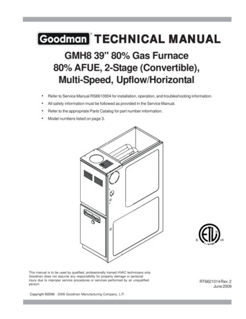
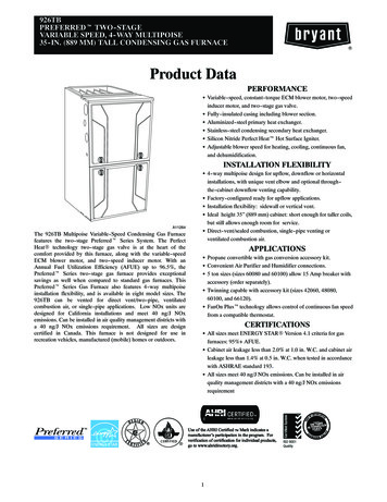
GAS FURNACES80 AFUEInstallation InstructionsSingle Stage High Efficiency Furnaces*SA Upflow/Horizontal ModelWARNING: PROPOSITION 65 WARNING: This productcontains chemicals known to the state ofCalifornia to cause cancer, birth defects orother reproductive harm. This furnace is not approved for installationin mobile homes. Installing this furnace ina mobile home could cause fire, propertydamage, and/or personal injury.ATTENTION INSTALLERS:It is your responsibility to know this product better than yourcustomer. This includes being able to install the product accordingto strict safety guidelines and instructing the customer on how tooperate and maintain the equipment for the life of the product.Safety should always be the deciding factor when installing thisproduct and using common sense plays an important role as well.Pay attention to all safety warnings and any other special noteshighlighted in the manual. Improper installation of the furnaceor failure to follow safety warnings could result in serious injury,death, or property damage.These instructions are primarily intended to assist qualifiedindividuals experienced in the proper installation of this appliance.Some local codes require licensed installation/service personnelfor this type of equipment. Please read all instructions carefullybefore starting the installation. Return these instructions to thecustomer’s package for future reference.*SK Downflow ModelWARNING:FIRE OR EXPLOSION HAZARD Failure to follow safety warnings exactlycould result in serious injury or propertydamage. Installation and service must be performedby a qualified installer, service agency orthe gas supplier. Do not store or use gasoline or otherflammable vapors and liquids in thevicinity of this or any other appliance.WHAT TO DO IF YOU SMELL GAS Do not try to light any appliance. Do not touch any electrical switch; do notuse any phone in your building. Leave the building immediately. Immediately call your gas supplier from aneighbor’s phone. Follow the gas supplier’sinstructions. If you cannot reach your gas supplier, callthe fire department.DO NOT DESTROY THIS MANUAL.KEEP IN A SAFE PLACE FOR FUTURE REFERENCE.
TABLE OF CONTENTSSAFETY INFORMATION .3REQUIREMENTS AND CODES .4FURNACE INSTALLATION .12General Requirements .12Upflow Installation .12GENERAL INSTRUCTIONS .4Combustion Air Quality .4Operation of Furnace During Construction .5Installation in a Garage .5Heating Load .5Clearances to Combustible Materials .5COMBUSTION AIR REQUIREMENTS .7General Information .7Installation in a Confined Space.7Air From Inside .7Side Return Air Inlet .12Bottom Return Air Inlet .12Horizontal Installation .12Downflow Installation .13Installation on a Concrete Slab .13Bottom Panel Removal .14Alternate Bottom Panel Removal .14GAS SUPPLY AND PIPING .15Leak Check .15High-Altitude Application .15Outdoor Air Using a Crawl Space orVented Attic .7Conversion to LP/Propane .17Outdoor Air Using Vertical Ducts .8ELECTRICAL WIRING .17Outdoor Air Using Horizontal Ducts .8Line Voltage Wiring .17Air Directly Through an Exterior Wall .8Low Voltage Wiring .18Alternate Method of Providing Air fromOutside .9Grounding .19Twinning.19Installation in an Unconfined Space .9START-UP & ADJUSTMENTS.20VENTING REQUIREMENTS.9Category I Venting .9Horizontal Venting. 10Flexible Vent Systems. 10Start-Up Procedures.20Verifying and Adjusting Input Rate .20Verifying and Adjusting Temperature Rise .20CIRCULATING AIR REQUIREMENTS .11Verifying Burner Operation .21Plenums and Air Ducts .11Verify Operation of the Supply AirLimit Switch .21Supply Air Connections .11Upflow/Horizontal Furnaces .11OPERATING SEQUENCE .21Downflow Furnaces.11Heating Cycle .21Return Air Connections .11Cooling Cycle .22Upflow/Horizontal Furnaces . 11Fan Mode .22Side Return Installations. 12Bottom Return Installations . 12Downflow Furnaces. 12Acoustical Treatments. 122Pre-Start Checklist .20TROUBLESHOOTING .22
MAINTENANCE .22Air Filters .22Blower Compartment .23Cleaning of Burners .23Cleaning of Flue Passages .23Heat Exchanger and Burner Maintenance .24Lubrication .24Vent System .24DESCRIPTION OF COMPONENTS .24FRENCH TRANSLATIONS .25FIGURES AND TABLES .27Figure 17 - Furnace Dimensions .27Airflow Data .28Table 4 - Upflow/Horizontal Gas Furnaces .28Table 5 - Downflow Gas Furnaces.30Electrical Information.31Figure 18 - Wiring Diagram .31Gas Information.32Table 6 - Gas Flow Rates.32Table 7 - Gas Pipe Capacities .32Table 8 - High Altitude Deration Chart forPropane Gas .33Table 9 - Natural Gas Heating Values .33Table 10 - High Altitude Deration Chart forNat. Gas - High Heating Values .34Table 11 - High Altitude Deration Chart forNat. Gas - Low Heating Values.34Location of Furnace Components .35Figure 19 - Upflow/Horizontal Gas FurnaceComponents .35Figure 20 - Downflow Gas FurnaceComponents .35INSTALLATION/PERFORMANCE CHECKLIST .36SAFETY INFORMATIONSafety markings are used frequently throughout thismanual to designate a degree or level of seriousness andshould not be ignored. WARNING indicates a potentiallyhazardous situation that if not avoided, could result inpersonal injury or death. CAUTION indicates a potentiallyhazardous situation that if not avoided, may result in minoror moderate injury or property damage.WARNING:The safety information listed below must befollowed during the installation, service, andoperation of this furnace. Failure to follow safetyrecommendations could result in possibledamage to the equipment, serious personalinjury or death. Use only with type of gas approved for this furnace.Refer to the furnace rating plate. Install this furnace only in a location and position asspecified in Table 1 (page 6). Provide adequate combustion and ventilation air to thefurnace space as specified on pages 7 - 9. Combustion products must be discharged outdoors.Connect this furnace to an approved vent system only,as specified on pages 9 - 10. Never test for gas leaks with an open flame. Use acommercially available soap solution to check allconnections. See page 15. This furnace is designed to operate with a maximumexternal pressure rise of 0.5 inches of water column.Consult Tables 4 - 5 (pages 28 - 30), and the ratingplate for the proper circulating air flow and temperaturerise. It is important that the duct system be designed tohandle the desired flow rate and temperature rise. Animproperly designed duct system can result in nuisanceshutdowns, and comfort or noise issues. When supply ducts carry air circulated by the furnaceto areas outside the space containing the furnace, thereturn air shall also be handled by duct(s) sealed tothe furnace casing and terminating outside the spacecontaining the furnace. See page 11. This furnace may be used for temporary heating ofbuildings or structures under construction. See theguidelines listed on page 5. A gas-fired furnace for installation in a residential garagemust be installed as specified on page 5.3
REQUIREMENTS and CODESThis furnace must be installed in accordance withthese instructions, all applicable local building codesand the current revision of the National Fuel Gas Code(NFPA54/ANSI Z223.1) or the Natural Gas and PropaneInstallation Code, CAN/CGA B149.1.Additional codes listed below are for referencepurposes only and do not necessarily havejurisdiction over local or state codes. Alwaysconsult with local authorities before installing anygas appliance.Combustion and Ventilation Air US: National Fuel Gas Code (NFGC), Air forCombustion and Ventilation CANADA: Natural Gas and Propane Installation Codes(NSCNGPIC), Venting Systems and Air Supply forAppliancesDuct Systems US and CANADA: Air Conditioning ContractorsAssociation (ACCA) Manual D, Sheet Metal andAir Conditioning Contractors National Association(SMACNA), or American Society of Heating,Refrigeration, and Air Conditioning Engineers(ASHRAE) Fundamentals HandbookElectrical Connections US: National Electrical Code (NEC) ANSI/NFPA 70 CANADA: Canadian Electrical Code CSA C22.1Gas Piping and Gas Pipe Pressure Testing US: NFGC and National Plumbing Codes CANADA: NSCNGPICGeneral Installation US: Current edition of the NFGC and the NFPA 90B.For copies, contact the National Fire ProtectionAssociation Inc., Batterymarch Park, Quincy, MA02269; or American Gas Association, 400 N. Capitol,N.W., Washington DC 20001 or www.NFPA.org CANADA: NSCNGPIC. For a copy, contact StandardSales, CSA International, 178 Rexdale Boulevard,Etobicoke (Toronto), Ontario, M9W 1R3 CanadaSafety US: (NFGC) NFPA 54–1999/ANSI Z223.1 and theInstallation Standards, Warm Air Heating and AirConditioning Systems ANSI/NFPA 90B. CANADA: CAN/CGA-B149.1 and .2–M00 NationalStandard of Canada. (NSCNGPIC)4GENERAL INSTRUCTIONSCombustion Air QualityCAUTION:Combustion air must not be drawn from acorrosive atmosphere.To maximize heat exchanger life, the combustion airmust be free of chemicals that can form corrosive acidiccompounds in the combustion gases. The recommendedsource of combustion air is to use outdoor air. However,the use of indoor air in most applications is acceptableexcept as listed: If the furnace is installed in a confined space, it isrequired that the necessary combustion air come fromthe outdoors by way of attic, crawl space, air duct, ordirect opening. For Installations in confined spaces,see pages 7 - 8 for combustion air requirements. Installations in these locations may require outdoor airfor combustion, due to chemical exposures:Commercial buildingsBuildings with indoor poolsFurnaces installed in laundry roomsFurnaces installed in hobby or craft roomsFurnaces installed near chemical storage areas Exposure to the following substances in the combustionair supply may require outdoor air for combustion:Permanent wave solutionsChlorinated waxes and cleanersChlorine based swimming pool chemicalsWater softening chemicalsDe-icing salts or chemicalsCarbon tetrachlorideHalogen type refrigerantsCleaning solvents (perchloroethylene)Printing inks, paint removers, varnishes, etc.Hydrochloric acidCements and gluesAntistatic fabric softenersMasonry acid washing materials
Operation of Furnace During ConstructionCAUTION:Installation in a GarageWARNING:Failure to follow these instructions will void thefactory warranty and may significantly reducethe life or the performance of the furnace,and/or result in other unsafe conditions. It isthe responsibility of the installing contractorto insure these provisions are met.Do not place combustible materials on oragainst the furnace cabinet or within 6 inchesof the vent pipe. Do not place combustiblematerials, including gasoline or any otherflammable vapors and liquids, in the vicinityof the furnace.Operating gas furnaces in construction environments cancause a variety of problems with the furnace. Proper useof commercial portable space heating equipment duringconstruction is recommended. This gas furnace may beused during construction if it is not in violation of anyapplicable codes and the following criteria are met: The installation must meet all applicable codes. Thefurnace must be permanently installed according tothe instructions with the furnace including electricalsupply, gas supply, duct work and venting. The furnacemust be controlled by a thermostat properly installedaccording to the instructions supplied with the furnaceand thermostat.The installation must include a properlyinstalled filter in the return air system with no by-passair. The filter must be inspected frequently and replacedwhen necessary. Combustion air must be supplied from outside thestructure and located such that dust and gasesfrom construction activity are not introduced into thecombustion system. Provisions must be made to insure that condensatedoes not freeze in the furnace or condensate drain linesduring operation and during idle times; for example,overnight if turned off. (Condensing furnaces only) Before occupying the structure: The filter must bereplaced or cleaned, the duct work must be inspectedand cleaned of any construction debris, and the furnacemust be cleaned and/or repaired if found to be dirty,damaged, or malfunctioning in any way by a qualifiedHVAC technician. The furnace shall be inspected andapproved by applicable local authority even if thisrequires redundant inspections. Serial numbers for furnaces used during constructionmust be submitted in writing (fax and email alsoacceptable). This information will be used to track thelong-term affects of the use during construction onfurnaces. Proof of this submittal shall be available forthe final inspection of the furnace prior to occupancy. This furnace is designed to operate with return airtemperatures in ranges normally found in occupiedresidences, including setbacks. Minimum continuousreturn temperature must not be below 60 F (15 C).Occasionally a temporary return temperature of 55 F(12 C) is acceptable. However, operation with a returntemperature below 55 F (12 C) is not allowed.This gas-fired furnace may be installed in a residentialgarage with the provision that the burners and igniterare located no less than 18 inches (457mm) above thefloor. The furnace must be located or protected to preventphysical damage by vehicles.Heating LoadThe furnace should be sized to provide the design heatingload requirement. Heating load estimates can be madeusing approved methods available from Air ConditioningContractors of America (Manual J); American Society ofHeating, Refrigerating, and Air Conditioning Engineers;or other approved engineering methods. Excessiveoversizing of the furnace could cause the furnaceand/or vent to fail prematurely.The ductwork should be appropriately sized to the capacityof the furnace to ensure its proper airflow rating. Forinstallations above 2,000 ft., the furnace should have asea level input rating large enough that it will meet theheating load after deration for altitude.Clearances to Combustible MaterialsThis furnace is Design Certified in the U.S. and Canadaby CSA International for the minimum clearances tocombustible materials listed in Table 1 (page 6). To obtainmodel number and specific clearance information, referto the furnace rating plate, located inside of the furnacecabinet.Access for positioning and servicing the unit must beconsidered when locating unit. The need to provideclearance for access to panels or doors may requireclearance distances over and above the requirements.Allow 24 inches minimum clearance from thefront of the unit. However 36 inches is stronglyrecommended.5
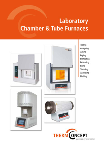
INSTALLATION CLEARANCES to COMBUSTIBLE MATERIALSFor UPFLOW, HORIZONTAL & DOWNFLOW FURNACESLeft Side.0 InchesVent. 1 InchTop .0 InchesRight Side .0 InchesBack .0 InchesFront. 4 Inches†UPFLOW APPLICATIONHORIZONTAL APPLICATIONDOWNFLOW APPLICATIONTOPTOPRIGHT SIDELEFT SIDEBOTTOMTOPLEFT SIDERIGHT SIDESIDESIDEBOTTOMBOTTOM†Allow 24 in. minimum clearance for servicing. Recommended clearance is 36 in.NOTE: The furnace is listed for installation on combustible or non-combustible flooring. However, wood is the only combustibleflooring allowed for installation. Downflow models must use the appropriate subase kit when installing over a wood floor.Table 1. Minimum Clearances to Combustible MaterialsWARNING:CARBON MONOXIDE POISONING HAZARDFailure to follow the steps outlined below for each appliance connected to the venting systembeing placed into operation could result in carbon monoxide poisoning or death. The followingsteps shall be followed with each individual appliance connected to the venting system beingplaced in operation, while all other appliances connected to the venting system are not inoperation:1. Seal any unused openings in the venting system.2. Inspect the venting system for proper size and horizontal pitch, as required in the NationalFuel Gas Code, ANSI Z223. 1/NFPA 54 or the CSA B149.1, Natural Gas and Propane InstallationCodes and these instructions. Determine that there is no blockage or restriction, leakage,corrosion and other deficiencies which could cause an unsafe condition.3. As far as practical, close all building doors and windows and all doors between the spacein which the appliance(s) connected to the venting system are located and other spacesof the building.4. Close fireplace dampers.5. Turn on clothes dryers and any appliance not connected to the venting system. Turn onany exhaust fans, such as range hoods and bathroom exhausts, so they are operating atmaximum speed. Do not operate a summer exhaust fan.6. Follow the lighting instructions. Place the appliance being inspected into operation. Adjustthe thermostat so appliance is operating continuously.7. Test for spillage from draft hood equipped appliances at the draft hood relief opening after5 minutes of main burner operation. Use the flame of a match or candle.8. If improper venting is observed during any of the above tests, the venting system mustbe corrected in accordance with the National Fuel Gas Code, ANSI Z223.1/NFPA 54 and/orCSA B149.1, Natural Gas and Propane Installation Codes.9. After it has been determined that each appliance connected to the venting system properlyvents when tested as outlined above, return doors, windows, exhaust fans, fireplacedampers and any other gas-fired burning appliance to their previous conditions of use.6
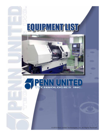
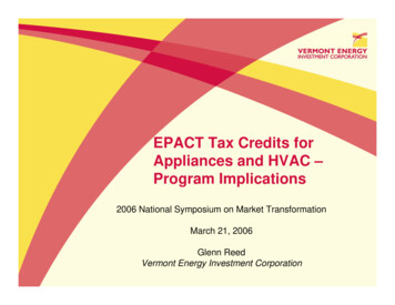
COMBUSTION AIR REQUIREMENTSGeneral InformationWARNING:Furnace installation using methods other thanthose described in the following sections mustcomply with the National Fuel Gas Code (NFGC)and all applicable local codes. Instructions for determining the adequacy of combustionair for an installation can be found in the current revisionof the NFGC (ANSI Z223.1 / NFPA54). Consult localcodes for special requirements.These requirementsare for US installations as found in the NFGC. The requirements in Canada (B149.1) are structureddifferently. Consult with B149.1 and local code officialsfor Canadian installations.Provisions must be made during the installation ofthis furnace that provide an adequate supply of air forcombustion.CAUTION:Exhaust fans, clothes dryers, fireplaces andother appliances that force air from the houseto the outdoors can create a negative pressureinside the house, resulting in improper furnaceoperation or unsafe conditions such as flame rollout. It is imperative that sufficient air exchangewith the outdoors is provided to preventdepressurization. Additional information abouthow to test for negative pressure problems canbe found in the NFGC.NOTE: Air openings on top of the furnace and openings incloset doors or walls must never be restricted. If the furnaceis operated without adequate air for combustion, the flameroll-out switch will open, turning off the gas supply to theburners. This safety device is a manually reset switch.DO NOT install jumper wires across these switchesto defeat their function or reset a switch withoutidentifying and correcting the fault condition.If a switch must be replaced, use only the correct sizedpart specified in the Replacement Parts List providedonline.Installation In A Confined SpaceA confined space is an area with volume less than 50cubic feet per 1,000 Btuh of the combined input rates ofall appliances drawing combustion air from that space.Furnace closets, small equipment rooms and garages areconfined spaces. Furnaces installed in a confined spacewhich supply heated air to areas outside the space mustdraw return air from outside the space and must have thereturn air ducts tightly sealed to the furnace.The required sizing of these openings is determined bywhether inside or outside air is used to support combustion,the method by which the air is brought to the space, andby the total input rate of all appliances in the space. Inall cases, the minimum dimension of any combustion airopening is 3 inches.Air From InsideIf combustion air is taken from the heated space, thetwo openings must each have a free area of at least onesquare inch per 1,000 Btuh of total input of all appliancesin the confined space, but not less than 100 squareinches of free area (Figure 1). See example.Example:If the combined input rate of all appliances is lessthan or equal to 100,000 Btuh, each opening musthave a free area of at least 100 square inches. If thecombined input rate of all appliances is 120,000 Btuh,each opening must have a free area of at least 120square inches.Vent orChimneyNOTES:Each opening mustbe at least 100 sq. in.or 1 sq. in. per 1,000Btuh of total input rating,whichever is greater.Openings must start atno more than 12 inchesfrom the top and bottomof the enclosure.12" Max.FurnaceSee NotesWaterHeaterTotal Input 0160,000SeeNotesMinimum Free Area(Each Opening)100 sq. In100 sq. In100 sq. In100 sq. In120 sq. In140 sq. In160 sq. In12” Max.Round DuctDiameter12 inches12 inches12 inches12 inches13 inches14 inches15 inchesFigure 1. Combustion Air Drawn from InsideOutdoor Air from a Crawl Space or Vented AtticWhen the openings can freely exchange air with theoutdoors, each opening shall have a minimum free areaof 1 square inch per 4,000 Btuh of total appliance input.The openings shall exchange directly, or by ducts, withthe outdoor spaces (crawl or attic) that freely exchangewith the outdoors (Figure 2, page 8).7
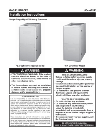
Ventilation louversat each end of atticAtticInsulationFurnaceInlet air duct must be atleast 1 sq. in. per 4,000Btuh of total input rating.Ventilated Louvers forunheated crawl spaceOutdoor Air Using Vertical DuctsIf combustion air is taken from outdoors through verticalducts, the openings and ducts must have a minimumfree area of one square inch per 4,000 Btuh of totalappliance input. In installations drawing combustion airfrom a ventilated attic, both air ducts must extend abovethe attic insulation (Figure 3).Ventilation Louvers ateach end of atticOutlet Air Duct mustbe at least 1 sq. in.per 4,000 Btuh oftotal input rating.AtticInsulationTotal Input 0160,000Air Duct---NOTE: Eachopening tooutside mustbe at least 1sq. in. per 2,000Btuh of totalinput rating.Water HeaterMinimum Free Area(Each Opening)10 sq. In15 sq. In20 sq. In25 sq. In30 sq. In35 sq. In40 sq. InRound DuctDiameter5 inches6 inches7 inches8 inches9 inches10 inches10 inchesAir Directly Through An Exterior WallIf combustion air is provided directly through an exteriorwall, the two openings must each have free area of atleast one square inch per 4,000 Btuh of total applianceinput (Figure 5).Inlet and OutletDucts mustextend aboveattic insulation.FurnaceInlet Air Duct mustbe at least 1 sq. in.per 4,000 Btuh oftotal input rating.12" MaxMinimum Free Area(Each Opening)100 sq. In100 sq. In100 sq. In100 sq. In120 sq. In140 sq. In160 sq. InVent orChimney---Round DuctDiameter12 inches12 inches12 inches12 inches13 inches14 inches15 inchesFigure 3. Combustion Air Drawn from OutsideThrough Vertical DuctsOutdoor Air Using Horizontal DuctsIf combustion air is taken from outdoors through horizontalducts, the openings and ducts must have a minimum freearea of one square inch per 2,000 Btuh of total applianceinput (Figure 4).8---Figure 4. Combustion Air Drawn from OutsideThrough Horizontal Ducts12" MaxTotal Input 0160,000Air DuctFurnaceSeeNote12" MaxFigure 2. Combustion Air Drawn from a CrawlSpace or Vented AtticWaterHeater------Crawl SpaceVent orChimney12" Max---WaterHeaterVent orChimneyOutlet air duct must beat least 1 sq. in. per4,000 Btuh of totalinput rating. Mustextend above atticinsulation---Vent orChimneyFurnaceSeeNote---12" MaxTotal Input 0160,000NOTE: Each openingto outside must be atleast 1 sq. in. per4,000 Btuh of totalinput rating.Water HeaterMinimum Free Area(Each Opening)10 sq. In15 sq. In20 sq. In25 sq. In30 sq. In35 sq. In40 sq. InRound DuctDiameter4 inches5 inches5 inches6 inches6 inches7 inches8 inchesFigure 5. Combustion Air Drawn from OutsideThrough an Exterior Wall
Alternate Method of Providing Air from Outside:If acceptable under local Codes, it is permitted toprovide outside air using one opening (See NFGC).Generally, confined spaces must have two openingsin the space for combustion air. One opening mustbe within 12 inches of the ceiling, and the othermust be within 12 inches of the floor. However, analternative method recently adopted by the NFGCuses one opening within 12 inches of the top of thespace. This method may be used if it is acceptableto the local codes.The following conditions must be met:1. The opening must start within 12” of the top of thestructure and connect with the out of doors throughvertical or horizontal ducts or be ducted to a crawlor attic space that connects with the out of doors.2. The opening must have a minimum free area of 1sq. in. per 3,000 Btu per hour of the total input ratingof all equipment located in the enclosure.3. The free area must not be less than the sum of allthe areas of the vent connectors in the enclosure.Installation In An Unconfined SpaceAn unconfined space is an area including all rooms notseparated by doors with a volume greater than 50 cubicfeet per 1,000 Btuh of the combined input rates of allappliances which draw combustion air from that space.In general, a furnace installed in an unconfined space willnot require outside air for combustion. However, in homesbuilt for energy efficiency (low air change rates), it maybe necessary to provide outside air to ensure adequatecombustion and venting, even though the furnace islocated in an unconfined space. See example.Example:A space with a water heater rated at 45,000 Btuhinput and a furnace rated at 75,000 Btuh requires avolume of 6,000 cubic feet [50 x (45 75) 6,000] tobe considered unconfined. If the space has an 8 footceiling, the floor area of the space must be 750 squarefeet (6,000 / 8 750).VENTING REQUIREMENTSWARNING:Upon completion of the furnace installation,carefully inspect the entire flue system bothinside and outside the furnace to assure it isproperly sealed. Leaks in the flue system canresult in serious personal injury or death dueto exposure of flue products, including carbonmonoxide. This furnace must be vented in compliance withthe current revision of the National Fuel Gas Code(ANSI-Z223.1/NFPA54) and the instr uctionsprovided below. Consult
the furnace casing and terminating outside the space containing the furnace. See page 11. This furnace may be used for temporary heating of buildings or structures under construction. See the guidelines listed on page 5. A gas-fi red furnace for installation in a residential garage must be installed as specifi ed on page 5.