Transcription
Advanced Battery Storage SystemsTesting at ACEPTHE PRUDENT ENERGY VRB-ESSCharacterization and Assessment of the Flow Battery Concept forEnergy Storage and Ancillary Services in Isolated Wind-DieselPower Networks in AlaskaMarch 2012
Cover photo: The power conversion system of the 5 kw, 20 kWhVanadium Redox Flow Battery courtesy of Prudent Energy.Any comments or suggestions may be directed to the authors atthe respective addresses below.Billy MuhandoAsst Research ProfAlaska Center for Energy and Power (ACEP)University of Alaska Fairbanksbemuhando@alaska.edu1 907 474 7082Tom JohnsonResearch EngineerAlaska Center for Energy and Power (ACEP)University of Alaska Fairbanksthjohnson@alaska.edu1 907 474 5564Further information may be obtained by contacting:Gwen HoldmannDirectorAlaska Center for Energy and Power (ACEP)University of Alaskagwen.holmann@alaska.edu1 907 474 5402www.uaf.edu/acepDisclaimerThis report was prepared by the Alaska Center for Energy and Power (ACEP) as an account of worksponsored by an agency of the United States Government – the Denali Commission – and is disseminatedin the interest of information exchange and general guidance only. Neither the United States Governmentnor any agency thereof, nor the state of Alaska, nor any of their employees, makes any warranty, express orimplied, or assumes any legal liability or responsibility for the accuracy, completeness, or usefulness of anyinformation, apparatus, product, or process disclosed, or represents that its use would not infringe privatelyowned rights. Reference herein to any specific commercial product, process, or service by trade name,trademark, manufacturer, or otherwise does not necessarily constitute or imply its endorsement,recommendation, or favoring by the United States Government, the state of Alaska, or any agency thereof.
AbstractWith the implementation of state and possibly federal renewable portfolio standards,there is a significant increase in the penetration of intermittent, non-dispatchableenergy sources, as evidenced by the upsurge in the deployment of wind-diesel systems inthe electricity generation infrastructure in various off-grid rural or village powerapplications in Alaska. The variability associated with these energy sources has asubstantial impact on the respective power networks, and energy storage provides oneapproach for addressing some of the impacts. Ancillary services have traditionally beenprovided by central power plants, but emerging business models are harnessing energystorage to fulfill these roles, including frequency regulation, synchronous reserve,reactive power, and renewables integration.High wind penetration systems can be enabled significantly by developing managed,efficient, reliable, and economical energy storage technologies that eliminate the needfor back-up utility baseload capacity to offset impacts of the intermittent resource.Large-scale energy storage signifies there is ‘energy on demand’ that enhances thereliability of the power system, can defer or reduce transmission system investments,and can capture alternative energy generated off-hours for use during peak load periods.Optimally, the energy storage solution should be a low-maintenance, environmentallyfriendly and modular construction to provide maximum benefit. Flow batteries showpotential for utility-scale electric energy storage that can improve the reliability andefficiency of the energy delivery network, and in turn, aid in the steady reduction ofdiesel usage and associated carbon emissions. Peak load shifting and energy arbitrageare other benefits that can be provided by these advanced energy storage systems.The Alaska center for Energy and Power (ACEP) has been involved in advanced batteryresearch by testing and evaluating battery systems for integration with renewable energyprojects on remote power grids in rural Alaska communities. This report documents themethodology, key assumptions, and results of a preliminary qualitative and quantitativeanalysis of a 5 kW, 20 kWh Prudent Energy flow battery system tested betweenSeptember 2010 and December 2011. The primary goal of the report is to shiftconventional thinking surrounding grid management and investment by initiatingstakeholder discussion regarding: a) the deployment of flow battery energy storage inwind-diesel systems in Alaska, and b) the investment needed to upgrade the currentpower systems to the higher performance levels required to support continued economicgrowth and improve productivity.
Blank
TABLE OF CONTENTSEXECUTIVE SUMMARY . Error! Bookmark not defined.iGLOSSARY . viINTRODUCTION AND THEORY OF OPERATION .1Need for Energy Storage .1Fundamentals of Vanadium Redox Flow Battery Systems . 2History of the Development of Flow Batteries . 2Vanadium Redox Flow Battery System . 3The ACEP Proposal and Award. 7Background and Context . 7Project Objectives/ Scope of Work . 7Project Timeline. 8Budget . 8Delivery . 9Commissioning . 10Characterization: Performance Testing and Analysis. 11Previous Work .12CHARACTERIZATION AND ANALYSIS .13Performance Testing .13Characteristics of the 5 Kw, 20 kWh Vanadium Redox Flow Battery .13Setting Up the Charge/Discharge Operation .15Operational Performance . 17Sample Charge/Discharge Cycle Operations . 17Efficiency . 24Features and Advantages of the VRB . 25PERSPECTIVES . 26Battery Charge and Discharge Characteristics . 26Efficiecy and Life-Cycle . 26Cost Considerations . 27Applications of the Technology. 29APPENDIX . A1System Overview . A1Cost Calculations . A5Datasheet: Specifications of the VRB-ESS .A6i
Blank
Executive SummaryProject BackgroundThe use of alternative and renewable energy sources on a large scale requires newtechnologies such as advanced energy storage systems. Multiple integration studies havesuggested that the challenge of integrating renewables increases in a non-linear fashionas penetration levels exceed 20%. Alaska is already home to several systems pairingwind turbines with diesel power plants, and one of the challenges for these systems isthe unpredictable wind system dynamics. Bulk storage is one of the major limitations intoday’s “just in time” electricity delivery system and one of the great opportunities forSmart Grid development in the future. In perspective and for Alaska in particular,storage—as both an end user and electric utility energy management resource —willbecome possible due to a confluence of high penetration wind-diesel systemsdeployment, dynamic pricing, and lower cost energy storage systems.The genesis of this project was a proposal for the Alaska Center for Energy and Power(ACEP), partnering with the UAF Chukchi Campus, to assess small-scale advancedstorage systems in support of the Kotzebue Electric Association (KEA) Premium PowerBattery Project. Funding was provided through the Denali Commission EmergingTechnologies Grant Fund for obtaining and testing the flow battery system. The fundingfor this project was intended as a sub-award to KEA’s larger grant in recognition of theneed to support ACEP’s research program in assessing other battery storage optionsappropriate for the Alaska market. The research project involved characterization of a 5kW, 20 kWh vanadium redox flow battery (VRB) system supplied by Prudent EnergySystems. The project has been conducted at the ACEP facilities in collaboration with theUAF Chukchi Campus, who purchased the battery for testing and will use datagenerated from this work as part of their sustainability curriculum. The project begun inSeptember 2010 and the first phase involved verifying manufacturer specifications.The program goals are twofold: 1) to provide early access of performance and durabilitydata for utilities that manage isolated grid systems to make informed decisions aboutfuture deployment of large-scale energy storage systems in Alaska, and 2) to improvethe academic research infrastructure at the University of Alaska Fairbanks related todistributed energy technologies. The overall analysis is based on testing and evaluationof the VRB unit to characterize the performance and durability of the technology byconsidering the duty cycle, discharge rate, dynamic voltage control on a distributionline, round-trip efficiency, cold climate operation, and other functioning issues. Initialresults have been encouraging – there is strong indication that vanadium redox flowbattery systems are potentially suitable for distribution grid support applications.ii
The VRB SystemPrudent Energy’s VRB storage system is an advanced flow battery technology designedto store and supply large amounts of electricity on demand. The VRB contains twodifferent electrolyte solutions of vanadium and sulfuric acid, each in a separate tank(positive and negatively charged, respectively). To provide power, the VRB electrolytesflow through a fuel cell stack on opposite sides of an ionic exchange membrane, wheretheir opposite charges create a gradient that powers an external current.Scalability: unlike conventional batteries, power output is independent from energystorage capacity—output depends on the size of the fuel cell stack, while the energystorage capacity depends on the size of the electrolyte tanks. This unique characteristicenables flow battery systems to sustain utility-scale storage and power at potentiallycompetitive prices. Note, however, that the ratio of storage to power determines howlong the batteries can run without recharging (power can flow undiminished as long asthere is fresh electrolyte to circulate through the stack).Research Findings and Pertinent IssuesThe experimental plan included running the battery to measure energy in and energyout as well as log any failures and performance issues. The focus has mostly been on theDC performance of the battery. Performance testing was limited to the scope of work asper the Award document, thus deep cycles to test degradation under chemicallyaggressive conditions was not carried out.Features of the Battery1. Spec sheet characteristics Power rating: 5 kW (designed energy charge/discharge rate) Energy storage capacity: 20 kWh (determined by tank size) Life: 10,000 cycles Operating temperature range: 10 degC to 35 degC Allowable storage temperature: -25 degC to 75 degC Weight: 510 kg ( 3,000 kg with electrolyte) Dimensions (power module only): 1m x 1.2 m x 1.1m2. Operational Performance The VRB unit has had a run time of 830 hours (this is the period coveredunder this report, and excludes initial commissioning and troubleshootinglog times). No. of complete cycles: 50 (average of 16 hrs charge/discharge cycles) Efficiency: between 70-78% (the base case state of charge was 10%-90%).iii
3. Economics of storage: 0.29/kWh (a simple economic calculation based on10,000 cycles at 20 kW-hr per cycle, or 200,000 kilowatt-hours total lifetimeenergy storage).Note, however, that the cost of VRB commercial units is currently placed at about 400/kW or 600/kWh.Some observations:1. Economic considerations – an assessment of the overall cost, in relation to otherstorage media and to other manufacturers/suppliers will determine whether theflow battery is justified in larger communities in conjunction with a wind turbineto stabilize delivered power.2. Battery life and maintenance – during the testing period the battery has exhibitedneither sign of degradation in performance nor balance of plant issues. Reliabilityof the battery relies on the maintenance of the system, while the maintenanceschedule intervals (cycles or service life hours) determine the offline duration.The design life of the battery is pegged at slightly over 10,000 cycles (and/or aservice life of 100,000 hrs). The electrolytes should in principle not get degraded,while it is expected that the cell stacks should be replaced every 10 years.3. Cold climate and operational limits – with regard to suitability for Alaska, theelectrolyte is fairly robust but is not to be exposed to extreme temperatures.Recommended electrolyte temperature range is 10 to 35 degC (during operation),while the allowable storage temperature range is -25 to 70 degC.However, there are also a number of disadvantages: Space requirements – the energy density of the storage system is relatively low,rendering a large footprint of the vanadium battery. The main components of theVRB include the storage tanks, pumps and plumbing, cell stacks, and powerconversion equipment. Footprint and volumetric space requirements scale withsystem ratings and can be very site-specific. The large quantity of vanadium electrolyte, which is ionic vanadium in sulfuricacid, is classified as corrosive. Containment – measures have to taken to avoid leakage to the environment.The application of flow batteries offers many opportunities, especially in large-scalegrid-connected applications. The first demonstration projects have demonstrated thetechnology on a large scale, but for characteristics like life time the technology first hasto prove itself in the coming years. Based on the expected life time costs, it is a veryattractive solution with both economical and technical benefits compared to thealternatives.iv
Future Perspectives of the TechnologyWind energy is a critical component of ACEP’s larger energy storage program objectives,both because many of the issues addressed as part of the program are unique to Alaska,and because the existing need is greatest in the energy sector based on total installedand planned projects. Technology that improves the reliability of wind or otherintermittent renewable energy resources fits with efforts to enhance Alaska’s energypicture and improve energy security. The flow battery storage system can serve tominimize runtimes of diesel generators while improving the functionality of windgeneration. The wind-diesel power system/flow battery integration, however, may stillhave room for improvement. The fundamental challenge is still the economics, andthese batteries are still relatively expensive for their energy density, though this isexpected to change as renewable energy becomes more common.The technical viability of a wind-coupled energy storage system is set for demonstrationby the Alaska Center for Energy and Power at the University of Alaska Fairbanks, wherethe 5 kW 20 kWh flow battery will be integrated with a 100 kW wind turbine simulatoron a test bed platform 1. The integrated approach will investigate benefits of suchstorage-coupled wind applications accrue in both directions: economic returns inspecialized cases such as island systems, and providing ride-through and transientmitigation from the perspective of the wind plant during grid disturbances.This decision has been taken on the premise that it is highly unlikely facilities at the Chukchi campuswould support the battery; part of the concern is the extra infrastructural cost for a dedicated structurethat complies with EPA regulations. Additionally, KEA is not keen on hosting the battery at their windfarm as they have already acquired the flow battery unit from Premium Power.1v
GlossaryThe following is a short explanation of some terminology and abbreviations used in thisreport for the Prudent Energy Storage System (“VRB”).AAmpere – unit of currentACAlternating current – the standard form of electricity from themains. Typically single phase for most domestic appliances;however three phases are used for higher power devicesBODBottom of discharge – Reference to beginning of battery charge cycleBOPBalance of plantCellThe smallest unit of a battery. In the flow battery many cells arepackaged together to form a stackCharge efficiencyRatio (%) between the energy removed from a battery duringdischarge compared with the energy used during charging torestore the original capacity. Also called the Coulombic Efficiency.ConverterAn electrical device for changing the voltage of an electricalsupply; used when a DC load runs at a different voltage to thebatteryCycleProcess of charging followed by discharging (or vice versa), tobring the battery back to the same state-of-charge (typicallycompletely discharged or charged). Battery life is often given asthe no. of cycles to a certain depth-of-dischargeDCDirect current – the standard form of electricity from a battery;may be used by some appliances but generally an inverter is usedto convert it to ACDepth-of dischargeHow much capacity has been taken out of the battery in %; e.g., an80% depth-of-discharge would leave 20% charge still in the batteryElectrolyte(In the VRB), a solution of vanadium salts in sulphuric acidESSEnergy storage system – a device that can be used to store energy(especially electricity) until it is neededvi
InverterAn electrical device for converting battery DC electricity intomains AC electricitykWKilowatt (thousand watt) – unit of power. Mathematically it isequal to the current multiplied by the voltagekWhKilowatt-hour – unit of energy (power multiplied by the usage time)LoadThe input impedance to the system circuit that takes electricity towork, and refers to any appliance connected to the flow batteryOxidation stateA numerical measure of the degree of oxidation of an atom in asubstance (how far the electrolyte has reacted). Vanadium in theVRB can have oxidation states 2 (little reacted), 3, 4 or 5(fully reacted)RedoxReduction-oxidation chemical reactionSmart controllerAn essential device in the VRB that continuously monitors thestate of the battery and power to the load(s). Controls the speed ofthe pumps, number of stages in operation, responds to alarmsignals and can communicate with the userSOCState-of-charge – how much capacity (%) remains in the batteryStackA group of cells through which the electrolytes flow. At both endsof the stack are electrical connectors through which the batterymay be charged and dischargedStageIn the VRB not all of the stacks must be active at the same time,especially when the power is low. The controller can decide toactivate or deactivate groups of stacks together, known as a stageThermal massA measure of how difficult it is to raise the temperature of anobject. The VRB has a higher thermal mass than an equivalentamount of lead-acid batteriesTOCTop of chargeVVolt – unit of voltage (or potential difference)VanadiumA common metal that is widely distributed in nature. It reacts toform brightly colored salts that are used in solution in the VRBvii
ACEP 12-03 March 2012Introduction and Theory of OperationNEED FOR ENERGY STORAGEStorage is essential for electricity consumers where power quality and reliability iscritical, such as at airports, broadcasting operations, hospitals, financial services, datacenters, telecommunications, and many finely tuned industrial processes. For gridsystems that have a significant amount of renewable generation, a means to provideancillary services is necessary to ensure power quality. Alaska has a number of isolatedpower systems that rely on diesel generators, wind turbines, or a combination of both.Hybrid wind-diesel systems, especially the high penetration types, require somespinning reserve component to ensure power quality. Generally speaking, it is relativelydifficult for the conventional generator to keep good power quality in a closed gridbecause the generator output cannot follow the demand change quickly.Developing the means to manage intermittent electricity generation from wind powerhas been a key challenge for grid operators. Whereas most power networks in the lower48 have various solutions in dealing with grid imbalances caused by wind e.g., networkinterconnection and demand management, energy storage remains the most viablealternative for wind-diesel systems in Alaska. Storage also incurs energy losses, around20-50% depending on the technology, which can put a dent in generating revenues.Energy loss during any of the conversion phases and during storage poses problems.Energy storage technologies are not an alternative to any particular resource decision,but rather, a valuable adjunct to all resources, and they allow increased capacity to bederived from any given quantity of physical resources. The goal for energy storagetechnologies is to stockpile massive amounts of energy by transforming it into differentbut conveniently stored forms. Storage systems rely on three key components: An input energy-conversion module that receives energy from the grid andconverts it to a storable form An energy-storage module that warehouses the energy, and An output-conversion module that turns the stored energy back into electricity.Lead-acid batteries represent the most prevalent form of electric energy storage forresidential, commercial and industrial customers wanting to maintain anuninterruptible power supply (UPS) system. However, storing massive amounts ofenergy from renewable resources requires rechargeable systems, like flow batteries.ADVANCED ENERGY STORAGE RESEARCH1 ACEP
ACEP 12-03 March 2012FUNDAMENTALS OF VANADIUM REDOX FLOW BATTERY SYSTEMSHistory of the Development of Flow BatteriesFlow batteries date back to the 19th century. They are best described as: ‘ a form ofbattery in which electrolyte containing one or more dissolved electro-active speciesflows through a power cell / reactor in which chemical energy is converted to electricity.Full-scale development of the batteries started in the 1970s. The principle of the redoxflow (RF) battery system was presented by L. H. Thaller of the National Aeronautics andSpace Administration (NASA) in 1974 1. NASA mainly conducted research on the Fe/Crsystem, discontinuing it in 1984 with the publication of the Final Report 2. At the sametime in Japan, the Electrotechnical Lab. (ETL; currently the National Institute ofAdvanced Industrial Science and Technology) was conducting basic research, and thedevelopment of the Fe/Cr system made progress as a project of the New Energy andIndustrial Technology Development Organization (NEDO).Flow batteries suitable for large scale energy storage have currently been developed atvarious organizations around the world. The Vanadium type of flow battery has becomea mature technology – this is a rechargeable flow battery that employs vanadium redoxcouples in both half-cells, thereby eliminating the problem of cross contamination bydiffusion of ions across the membrane. Although the use of vanadium redox couples inflow batteries had been suggested earlier by Pissoort 3, by NASA researchers, and byPellegri and Spaziante 4 in 1978, the first successful demonstration and commercialdevelopment was by Prof Maria Skyllas-Kazacos and co-workers at the University ofNew South Wales (UNSW) in Australia in the 1980's 5,6. UNSW proceeded to develop thevanadium redox battery and patented it 7,8 – this resembled the present form (withsulfuric acid electrolytes). It is noteworthy that vanadium resources are abundantlyavailable in Australia.L. H. Thaller, “Electrically Rechargeable Redox Flow Cells,” Proc. Of the 9th IECEC, P.924 (1974).N. H. Hagedorn, “NASA Redox Storage System Development Project Final Report,” DOE/NASA/12726-24, NASATM-83677 (1984).3 P. A. Pissoort, in FR Patent 754065 (1933).4 A. Pelligri and P. M. Spaziante, in GB Patent 2030349 (1978), to Oronzio de Nori Impianti Elettrochimici S.p.A.5 B. Sun, M. Skyllas-Kazacos, “A Study of the V(II)/V(III) Redox Couple for Redox Cell Application,” J. of Power Sources,15, P.179-190 (1985)6 M. Rychcik and M. Skyllas-Kazacos, “Characteristics of a new all-vanadium redox flow battery,” Journal of PowerSources, 22, P.59-67, 1988.7 M. Skyllas-Kazacos, M. Rychcik, and R. Robins, in AU Patent 575247 (1986), to Unisearch Ltd.8 M. Skyllas-Kazacos, M. Rychick, R. Robins, All-vanadium redox battery, US Patent 4,786,567 (November 1988).12ADVANCED ENERGY STORAGE RESEARCH2 ACEP
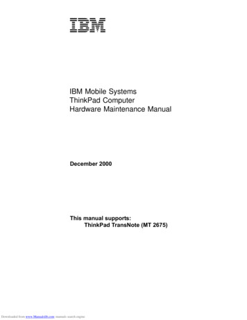
ACEP 12-03 March 2012Vanadium Redox Flow Battery SystemThe word redox is a combination of, and thus stands for, reduction and oxidation. Aredox battery refers to an electrochemical system that generates oxidation and reductionbetween two active materials, forming a redox system, on the surface of inactiveelectrodes. A redox flow battery has the electrolyte including these active materials inexternal containers, and charges and discharges electricity by supplying the electrolyteto the flow type cell by pumps or other means.Fig. 1. VRB systemFig. 1 shows Prudent Energy’s VRB system. The three primary subsystems in the VRBare the converter, the power conversion module, and the electrolyte – the energy storagemedium. The converter is the interface between the DC battery voltage and the 60 HzAC network voltage. The converter transformers match the converter output to the gridsystem voltage. The VRB uses vanadium salts and sulfuric acid in the electrolytes toconvert chemical energy into electrical energy. Vanadium is a relatively common metal,used to make vanadium steels and dietary supplements and is found in many commonfoods.ADVANCED ENERGY STORAGE RESEARCH3 ACEP
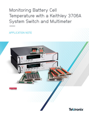
ACEP 12-03 March 2012Fig. 2. Construction of the cell stack.Generally the cells are grouped together in blocks known as stacks. In each stack thecells are connected electrically in series by bipolar plates, i.e. conducting plates that havepositive electrolyte on one side and negative on the other. Each cell of a flow battery ispractically identical, because they share the same electrolytes. Therefore, the stackvoltage is the sum of the voltage of the individual cells. The main components of a cellstack are shown in Fig. 2.Fig. 3 is a schematic of theoperation of the VRB. Thephilosophy of operation is basedon the fact that when connectedto the electrical network, thebattery cells store energy throughcharging; this energy is laterreleased to the power systemduring the discharge cycles –ideal for storage of excessgeneration from distributedresources (wind turbines).During charging, electrolyte flow is forced across both sides of an ionic exchangemembrane as electrical current is applied to the VRB-ESS cell stack. This results in anelectrochemical reaction forcing protons to pass through the membrane causing achange in the vanadium valence. This change in valence represents stored chemicalenergy that can be recovered by reversing the process through the VRB-ESS cell stack.Control of flow conditions and electrical performance is automatically maintained by thebattery controller.ADVANCED ENERGY STORAGE RESEARCH4 ACEP
ACEP 12-03 March 2012Oxidation StatesFig. 4. Principle of the Vanadium Redox flow battery 9.Fig. 4 illustrates the redox concept. The VRB consists of an assembly of power cells inwhich the two electrolyte solutions with a different redox potential are kept separated byan ion exchange membrane. This membrane allows one electrolyte to ionize the other byexchanging electrons while preventing the two solutions to physically mix.Both electrolytes are vanadium based – the electrolyte in the positive half-cells containsVO2 and VO2 ions, the electrolyte in the negative half-cells, V3 and V2 ions. Theelectrolytes are typically prepared by a number of processes, including electrolyticallydissolving vanadium pentoxide (V2O5) in sulfuric acid (H2SO4). The solution remainsstrongly acidic in use. Both half-cells are additionally connected to storage tanks andpumps so that very large volumes of the electrolytes can be circulated through the cell.Generally, metal ions that change valence c
Testing at ACEP . THE PRUDENT ENERGY VRB-ESS . . there is a significant increase in the penetration of intermittent, non-dispatchable . The genesis of this project was a proposal for the Alaska Center for Energy and Power (ACEP), partnering with the UAF Chukchi Campus, to assess small-scale advanced .

![Smarter Battery Crack [2022-Latest]](/img/13/eliamari.jpg)