Transcription
Joint Optimization for Robust NetworkDesign and OperationJennifer GosselsA DissertationPresented to the Facultyof Princeton Universityin Candidacy for the Degreeof Doctor of PhilosophyRecommended for Acceptanceby the Department ofComputer ScienceAdvisor: Professor Jennifer RexfordApril 2020
c Copyright by Jennifer Gossels, 2020.All rights reserved.
AbstractThe Internet is an essential part of modern life, and Internet Service Provider (ISP) backbonenetworks are integral to our Internet experience. Therefore, ISPs must build networks thatlimit congestion, even when some equipment fails. This network design problem is complicated, because an optimal network design must consider the eventual runtime configuration.An ISP makes network design decisions, such as purchasing and placing equipment, on longtimescales (months or years) and network operation decisions, such as routing packets, onshort timescales (seconds). Design and operation interact such that the ISP must solve thenetwork operation problem as a sub-problem of network design, rendering the network designproblem difficult to formulate and computationally complex.Today ISPs resort to a variety of simplifications; they fail to take advantage of thereconfigurability offered by modern optical equipment or the opportunity to mix more- andless-powerful switches throughout their networks. In this dissertation, we show how ISPs canincorporate each of these factors into their network design and operation models to produceless expensive networks without compromising robustness.In Chapter 2, we explain how reconfigurable optical switches fundamentally change thenetwork design and operation problems by shifting the boundary between what is fixed atdesign time and what is reconfigured at runtime. Then, we present an optimal formulationfor this new problem and heuristics to help our solution scale. In Chapter 3, we describe afailure recovery protocol that allows ISPs to realize many of the benefits of outfitting theirnetworks with a homogeneous collection of powerful, “smart” switches, while instead usinga combination of these expensive boxes and less expensive, “dumb” switches.We make three contributions in each chapter. First, we formulate the network designoptimization by extending the multicommodity flow framework to leverage colorless anddirectionless Reconfigurable Optical Add/Drop Multiplexers (Chapter 2) or heterogeneousnodes (Chapter 3). Second, we devise heuristics to scale our designs to larger topologies.Finally, we evaluate our ideas on a realistic backbone topology and traffic demands.iii
AcknowledgmentsPrincetonAdvisorThesis CommitteeJennifer RexfordGagan ChoudhuryMichael FreedmanKai LiWyatt LloydChapter 2AT&TCommentsGagan ChoudhuryKathy Meier-HellsternSimon TseMina Tahmasbi ArashlooManya GhobadiXin JinSanjay RaoChapter 3CollaboratorDataRonaldo A. FerreiraGagan Choudhury/AT&TFundingNational Science FoundationGraduate Research FellowshipGrant CCF-1837030MiscellaneousProofreadingChapter TitlesEverythingBonnie GosselsJamie GosselsBoston Red SoxFamilyiv
v
ContentsAbstract . . . . . . . . . . . . . . . . . . . . . . . . . . . . . . . . . . . . . . . . .iiiAcknowledgments . . . . . . . . . . . . . . . . . . . . . . . . . . . . . . . . . . . .ivList of Tables . . . . . . . . . . . . . . . . . . . . . . . . . . . . . . . . . . . . . .ixList of Figures . . . . . . . . . . . . . . . . . . . . . . . . . . . . . . . . . . . . . .xBibliographic Notes . . . . . . . . . . . . . . . . . . . . . . . . . . . . . . . . . . .xii1 Introduction1.11Network Design and Operation Today . . . . . . . . . . . . . . . . . . . . . .21.1.1Network Design . . . . . . . . . . . . . . . . . . . . . . . . . . . . . .31.1.2Network Operation . . . . . . . . . . . . . . . . . . . . . . . . . . . .61.1.3Coupling of Network Design and Operation . . . . . . . . . . . . . .8Network Design and Operation Tomorrow . . . . . . . . . . . . . . . . . . .101.2.1Reconfigurable Optics . . . . . . . . . . . . . . . . . . . . . . . . . .101.2.2Heterogeneous Nodes . . . . . . . . . . . . . . . . . . . . . . . . . . .111.3Contributions . . . . . . . . . . . . . . . . . . . . . . . . . . . . . . . . . . .131.4Summary . . . . . . . . . . . . . . . . . . . . . . . . . . . . . . . . . . . . .141.22 Sox: S trategic Optical/IP X -Layer Network Design152.1Introduction . . . . . . . . . . . . . . . . . . . . . . . . . . . . . . . . . . . .152.2IP/Optical Failure Recovery . . . . . . . . . . . . . . . . . . . . . . . . . . .202.2.120IP/Optical Network Architecture . . . . . . . . . . . . . . . . . . . .vi
2.32.42.2.2Failure Recovery in Traditional Networks . . . . . . . . . . . . . . . .212.2.3Failure Recovery in CD ROADM Networks . . . . . . . . . . . . . . .24Network Design Problem . . . . . . . . . . . . . . . . . . . . . . . . . . . . .262.3.1Minimizing Network Cost . . . . . . . . . . . . . . . . . . . . . . . .272.3.2Robust Placement of Tails and Regens . . . . . . . . . . . . . . . . .282.3.3Dynamic Placement of IP Links . . . . . . . . . . . . . . . . . . . . .312.3.4Extensions to a Wider Variety of Settings . . . . . . . . . . . . . . .32Scalable Approximations . . . . . . . . . . . . . . . . . . . . . . . . . . . . .342.4.1SimpleParallelizing of Failure Scenarios . . . . . . . . . . . . . . . . .352.4.2GreedySequencing of Failure Scenarios . . . . . . . . . . . . . . . . . .352.4.3Roles of. . . . . . . . . . . . . . . . . . . . .36Evaluation . . . . . . . . . . . . . . . . . . . . . . . . . . . . . . . . . . . . .372.5.1Experiment Setup . . . . . . . . . . . . . . . . . . . . . . . . . . . . .382.5.2Benefits of CD ROADMs . . . . . . . . . . . . . . . . . . . . . . . . .402.5.3Scalability Benefits of. . . . . . . . . . . . . . . . . . . . . . .412.5.4Behavior During IP Link Reconfiguration . . . . . . . . . . . . . . . .432.5.5Evaluation on a Realistic Backbone Topology . . . . . . . . . . . . .442.6Related Work . . . . . . . . . . . . . . . . . . . . . . . . . . . . . . . . . . .472.7Conclusion . . . . . . . . . . . . . . . . . . . . . . . . . . . . . . . . . . . . .482.5Simple, Greedy,andOptimalGreedy3 Red: A Communist Approach to Network Operation3.150Introduction . . . . . . . . . . . . . . . . . . . . . . . . . . . . . . . . . . . .503.1.1Chapter Outline . . . . . . . . . . . . . . . . . . . . . . . . . . . . . .553.2Overlay Model . . . . . . . . . . . . . . . . . . . . . . . . . . . . . . . . . . .563.3Traffic Engineering . . . . . . . . . . . . . . . . . . . . . . . . . . . . . . . .583.3.1Extending MCF . . . . . . . . . . . . . . . . . . . . . . . . . . . . . .603.3.2Enforcing Splitting Constraints . . . . . . . . . . . . . . . . . . . . .623.3.3Reducing Computation Time . . . . . . . . . . . . . . . . . . . . . .63vii
3.3.43.43.5Putting it All Together . . . . . . . . . . . . . . . . . . . . . . . . . .63Failure Recovery . . . . . . . . . . . . . . . . . . . . . . . . . . . . . . . . .643.4.1Local Recovery . . . . . . . . . . . . . . . . . . . . . . . . . . . . . .643.4.2Global Recovery . . . . . . . . . . . . . . . . . . . . . . . . . . . . . .66Evaluation . . . . . . . . . . . . . . . . . . . . . . . . . . . . . . . . . . . . .683.5.1Traffic Engineering . . . . . . . . . . . . . . . . . . . . . . . . . . . .683.5.2Failure Recovery . . . . . . . . . . . . . . . . . . . . . . . . . . . . .703.6Explaining the Limited TE Impact of. . . . . . . . . . . . . . . . .733.7Related Work . . . . . . . . . . . . . . . . . . . . . . . . . . . . . . . . . . .743.7.1TE and Failure Recovery: Established Standards . . . . . . . . . . .743.7.2TE and Failure Recovery: Research Proposals . . . . . . . . . . . . .763.7.3Incremental Deployment . . . . . . . . . . . . . . . . . . . . . . . . .77Conclusion . . . . . . . . . . . . . . . . . . . . . . . . . . . . . . . . . . . . .773.8big nodes4 Conclusion4.14.278Summary of Contributions . . . . . . . . . . . . . . . . . . . . . . . . . . . .794.1.1Sox . . . . . . . . . . . . . . . . . . . . . . . . . . . . . . . . . . . .794.1.2Red . . . . . . . . . . . . . . . . . . . . . . . . . . . . . . . . . . . .79Future Work . . . . . . . . . . . . . . . . . . . . . . . . . . . . . . . . . . . .80. . . . . . . . . . . . . . . . . . . . . . . . . . . . .814.2.1Red SoxBibliography82viii
List of Tables1.1Network Design and Operation Inputs, Outputs, Constraints, and Objectives32.1Properties of Failure Recovery Approaches . . . . . . . . . . . . . . . . . . .222.2Sox Notation . . . . . . . . . . . . . . . . . . . . . . . . . . . . . . . . . . .283.1Properties of TE/Failure Recovery Architectures . . . . . . . . . . . . . . . .533.2Red Notation . . . . . . . . . . . . . . . . . . . . . . . . . . . . . . . . . . .59ix
List of Figures1.1Hierarchical Structure of the Internet . . . . . . . . . . . . . . . . . . . . . .21.2Interdependence of the Network Design and Operation Problems . . . . . . .91.3Design vs. Operation in Traditional and Modern Networks . . . . . . . . . .121.4Network Designs and Associated Routing Models . . . . . . . . . . . . . . .132.1Layered IP/Optical Architecture . . . . . . . . . . . . . . . . . . . . . . . . .162.2Design vs. Operation in Traditional Networks, Existing CD ROADM Work,and Sox . . . . . . . . . . . . . . . . . . . . . . . . . . . . . . . . . . . . . .172.3IP/Optical Network Terminology . . . . . . . . . . . . . . . . . . . . . . . .192.4Optical Network Illustrating Different Options for Failure Restoration . . . .222.5Topology Used for Experiments . . . . . . . . . . . . . . . . . . . . . . . . .392.6Total Cost for402.7Cost by Computation Time for. . . . . . . . . . . .422.8Traffic Carried on Existing IP Topology . . . . . . . . . . . . . . . . . . . . .443.1Topology Illustrating How Edge-to-Edge Tunneling Limits Path Diversity . .563.2Example Physical and Overlay Topologies . . . . . . . . . . . . . . . . . . .573.3big nodeTable Pipeline . . . . . . . . . . . . . . . . . . . . . . . . . . . . . . .583.4Red LP . . . . . . . . . . . . . . . . . . . . . . . . . . . . . . . . . . . . . .613.5Red TE Algorithm . . . . . . . . . . . . . . . . . . . . . . . . . . . . . . . .65OptimalandLegacy. . . . . . . . . . . . . . . . . . . . . . . . .Simple, Greedy,xandOptimal
3.6Topology Illustrating Why We Need to Remove Initially Unused big nodes Fromnhbn3.7. . . . . . . . . . . . . . . . . . . . . . . . . . . . . . . . . . . . . . . . .67Fraction of Trials for Which Maximum Link Utilization is at Most a CertainValue (No Link Failures) . . . . . . . . . . . . . . . . . . . . . . . . . . . . .693.8big node-to-big node713.9Fraction of Trials for Which Maximum Link Utilization is at Most a CertainPath Lengths . . . . . . . . . . . . . . . . . . . . . . . . . .Value (Link Failures) . . . . . . . . . . . . . . . . . . . . . . . . . . . . . . .xi72
Bibliographic NotesA version of Chapter 2 appears in the August 2019 edition of the Journal of Optical Communications and Networking [27], co-authored with Gagan Choudhury and Jennifer Rexford.Chapter 3 is derived from joint work with Ronaldo A. Ferreira and Jennifer Rexford.xii
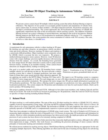
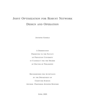
Chapter 1IntroductionThe Internet plays an integral role in nearly all aspects of modern life, and Internet ServiceProvider (ISP) backbone networks play a critical role in the functioning of the Internet. TheInternet is a hierarchical “network of networks,” and these ISP backbones sit at the topof the hierarchy (Figure 1.1). End systems such as laptops, cell phones, web servers, mailservers, and toasters connect to home, enterprise, or data center networks, which in turnconnect to one or more access ISP networks. Regional ISP networks join together several ofthese access ISP networks, and regional ISPs in turn communicate with each other via Tier1 ISPs or directly by connecting at Internet exchange points (IXPs). Tier 1 ISPs such asAT&T and Verizon maintain backbone networks that span an entire country and serve asthe “glue” connecting thousands of these smaller networks.Thus, given their position at the top of the hierarchy, Tier 1 ISP backbones carry trafficfrom millions of users each day. These users rely on these networks to provide reliable, rapidcommunication at all times — a surgeon simply can’t afford for the Internet to “break” in themidst of a procedure, nor can a Red Sox fan streaming an important playoff game tolerate adisruption. Unfortunately for ISPs, the physical links and switches comprising their networkssometimes do fail. It is their responsibility to design and operate their networks such thatthese failures are largely transparent to their customers.1
Figure 1.1: Hierarchical structure of the Internet. End systems connect to enterprise, home,or data center networks, which connect to access ISP networks. Multiple access ISP networksjoin together at each regional ISP network, which are themselves joined together by Tier 1ISPs. Figure adapted from Figure 1.15 of [42].In the next section, we explore the network design and operation problems in more detail,defining some key terminology and discussing how ISPs solve these problems today.1.1Network Design and Operation TodayAn ISP makes some decisions, such as how much and what type of equipment to purchaseand where to place this equipment, on large timescales on the order of months, and otherdecisions, such as exactly how to route packets from a given flow, on small timescales onthe order of seconds. We say that these large-timescale decisions constitute network design,2
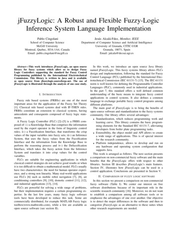
fic matrixPoP/fiber locationsfailure scenariosnetwork topologycarry all trafficmin. equipment costsoperationtraffic matrixtopology(failure scenarios)routing of traffic over linkslink bandwidthsmin. congestionTable 1.1: Inputs, outputs, constraints, and objectives of the network design and operationproblems.and these small-timescale decisions constitute network operation. For the ISP, both networkdesign and operation require solving constrained optimization problems; the ISP must useinput information about aspects of its network that it can’t change to produce a set ofoutput decisions, with the goal of optimizing a particular business objective and subject tocertain real-world constraints. In the following subsections, we describe the inputs, outputs,constraints, and objectives of each, and Table 1.1 summarizes this discussion.1.1.1Network DesignA computer network is a graph whose nodes are switches and routers and whose edges arelinks. We use the terms switches and routers interchangeably, since the distinction betweenthem is unimportant for our work. A network topology is the physical structure of this graph:the number, type, and locations of switches and how these switches are connected, includingthe bandwidth capacity of each link. Network design entails specifying a network topology,subject to the constraint that the chosen topology must be able to carry the offered trafficmatrix. The traffic matrix is a specification of the (nonnegative but possibly zero) amount oftraffic that each edge switch wants to send to each other edge switch. Of course, the ultimatesources and destinations of all packets are the end systems, but since we are concerned withthe design and operation of ISP backbones, for our purposes these individual demands areaggregated at edge switches. Unlike in private backbones such as Google’s B4 [35], an ISPhas no control over the amount of traffic that each end host sends or in the timing of whenpackets enter the network. Further, packets must be delivered in a timely fashion; the ISP3
need not send them on the absolute shortest paths, but it can’t use excessively circuitousroutes, nor can it buffer packets at busy times and wait to send them when the network isless congested.In reality, the network will be expected to carry a variety of traffic matrices, as trafficpatterns change throughout the day and over the course of months and years. When we referto the single traffic matrix, we assume that these demands represent the maximum demandsthe network will ever be responsible for; we assume that this traffic matrix “covers” allothers. It is straightforward but beyond the scope of this thesis to extend our techniques toadapt to changing traffic matrices.Hence, solving the network design problem amounts to answering the following questions: How many and what type of switches and routers should be placed at each potentiallocation?For our purposes, choosing a set of potential locations for switches and routers is notpart of network design; we assume that an ISP has already fixed the set of cities inwhich it wants to place points-of-presence (PoPs) and where in each city its PoP will belocated. These PoPs are the potential locations for switches and routers, and networkdesign involves placing switches at each PoP. How should these switches and routers be connected? What bandwidth should eachlink support?We do not choose where to lay fiber as part of network design; we assume that theISP has already laid its fiber in the ground. Importantly, the amount of fiber laidbetween PoPs is not a limiting factor in the bandwidth of the links between said PoPs.Rather, the limiting factor is the number of interfaces located on switches at each PoP,along with the number of optical regenerators located along an IP link’s path to ensurethat its optical signal reaches far away destinations. Hence, network design involves4
determining what bandwidth IP link each stretch of fiber should support, but it doesnot allow for specifying additional paths for new fiber installations.Robustness to FailuresA key part of the network design problem is ensuring that the topology will be robust toequipment failures. A fiber link can fail if, for example, it is accidentally cut during aconstruction project. Switches can fail if, for example, they lose power, are misconfigured,or encounter a hardware problem. Sometimes one or two of a switch’s ports can fail while therest remain operational. We use the term failure scenario to refer to any given simultaneouscombination of specific switch or link failures.In practice ISPs generally design their networks to be robust to certain classes of failurescenarios such as any single link failure, any single switch failure, any single link or switchfailure, any combination of two link/switch failures, etc. Another important considerationis shared link risk groups. Failures are not randomly distributed throughout the network.Rather, if a natural disaster or construction accident destroys one IP link on the East Coast ofthe United States, it likely will affect nearby links, too. Hence, links that are geographicallyclose together or are built upon common stretches of fiber are said to be part of a singleshared link risk group. Often, an ISP designs its network to be robust to all the links ineach shared link risk group failing simultaneously.The need to account for failure scenarios greatly increases the complexity of the networkdesign problem. Even without considering multiple failure scenarios, problem complexitygrows as a function of the size of the network, because the solution must specify the locationsfor more switches and links. Failure scenarios exacerbate this problem, since the numberof failure scenarios itself increases as the size of the network increases; the more nodes andlinks a network has, the more failure scenarios are included in e.g., the set consisting of allsingle node or link failures.5
How Network Design is Done TodayA strawman approach to finding a feasible solution to the network design problem is todramatically overprovision the network. If the ISP builds, e.g., two extra, redundant linksfor each link it actually needs, the network likely will not get too congested, even in the caseof failures. However, buying the equipment to provision this network is costly for the ISP;while this idea gives a feasible solution to the constrained optimization proble
An ISP makes network design decisions, such as purchasing and placing equipment, on long timescales (months or years) and network operation decisions, such as routing packets, on short timescales (seconds). Design and operation interact such that the ISP must solve the