Transcription
INSTRUCTION MANUALOrion SkyQuest XTiIntelliScope DobsonianTelescopes#10026 XT6i, #10018 XT8i, #10019 XT10i, #10020 XT12iFrancais➊ Pour obtenir le manuel d'utilisationcomplet, veuillez vous rendre sur le site WebOrionTelescopes.eu/fr et saisir la référencedu produit dans la barre de recherche.➋ Cliquez ensuite sur le lien du manueld’utilisation du produit sur la page dedescription du produit.Deutsche➊ Wenn Sie das vollständige Handbucheinsehen möchten, wechseln Sie zu OrionTelescopes.de, und geben Sie in der Suchleistedie Artikelnummer derOrion-Kamera ein.➋ Klicken Sie anschließend auf der Seite mitden Produktdetails auf den Link des entsprechenden Produkthandbuches.Español➊ Para ver el manual completo, visite OrionTelescopes.eu y escriba el número de artículo del producto en la barra de búsqueda.➋A continuación, haga clic en el enlace almanual del producto de la página de detalledel producto.Corporate Offices: 89 Hangar Way, Watsonville CA 95076 - USAToll Free USA & Canada: (800) 447-1001International: 1(831) 763-7000Customer Support: ght 2020 Orion Telescopes & Binoculars. All Rights Reserved. No part of this product instruction or any of its contents may be reproduced, copied,modified or adapted, without the prior written consent of Orion Telescopes & Binoculars.IN 226 Rev. J 09/12
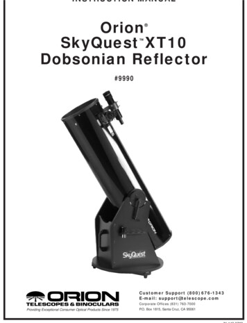
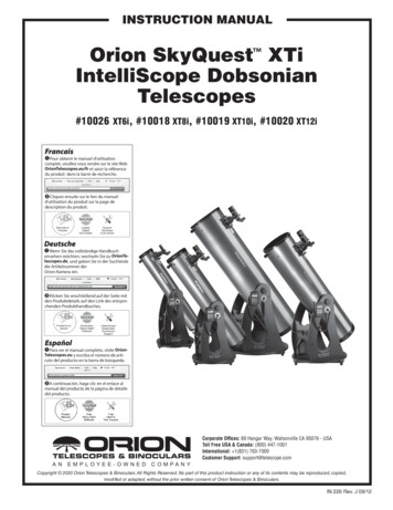
FinderscopeSecondary mirror holderwith 4-vane spider(not visible)Finder scope bracketEyepieceFocuserNavigationknobOptical tubeAltitudetensioningknobRetaining knob(opposite side)ComputerizedObject LocatorIntelliScope ControllerPort modular jackRight side panelPrimarymirror cellFront braceEyepiecerackLeft side panelHandleTop baseplateGround baseplateFoot (3)Figure 1. The SkyQuest XT8 IntelliScope2
Congratulations on your purchase of an Orion SkyQuest XTi IntelliScope Dobsonian. It is a high-performance astronomical instrument designed to provide dazzling views of celestial objects and unprecedented ease of use. With the addition of the optional IntelliScope Computerized Object Locator (Controller),you gain the ability to locate and view thousands of celestial objects with the push of a button. Searchingfor faint objects – so often a source of frustration for telescope users – is a thing of the past, as the IntelliScope’s high-resolution digital encoders find them for you in seconds. It’s so easy!Your SkyQuest IntelliScope will provide years of stargazing enjoyment, thanks to its large-aperture, precision optics; its innovative, user-friendly design; its complement of outstanding features and accessories; and most of all, its easy object locating technology. We hope you enjoy your journey through theuniverse!Please read these instructions thoroughly before beginning assembly and subsequent use of the telescope.Parts ListTable of Contents1. Unpacking32. Assembly43. Using Your Telescope114. Alignment (Collimation) of the Optical System145. Astronomical Observing176. IntelliScope Computerized Object Location207. Care and Maintenance208. Specifications211. UnpackingThe telescope is packed in two boxes (three for the XT12i),one containing the optical tube assembly and accessories,the other containing the unassembled Dobsonian base (thethird box for the XT12i includes the mirror and cell). Be careful unpacking the boxes. We recommend keeping the originalshipping containers. In the event that the telescope needs tobe shipped to another location, or returned to Orion for warranty repair, having the proper shipping containers will help ensurethat your telescope will survive the journey intact.Make sure all the parts in the Parts List are present. Be sureto check boxes carefully, as some parts are small. If anythingappears to be missing or broken, immediately call Orion Customer Support (800-676-1343) or email:sales@telescope.com for assistance.WARNING: Never look directly at the Sunthrough your telescope or its finder scope—even for an instant—without a professionallymade solar filter that completely covers thefront of the instrument, or permanent eyedamage could result. Young children should usethis telescope only with adult supervision.Box #1: Optical Tube Assembly and AccessoriesQty Description1 Optical tube assembly1Dust cover125mm Sirius Plössl eyepiece, 1.25"110mm Sirius Plössl eyepiece, 1.25"19x50 Right-angle correct-image finder scope (6x30for the XT6i) with bracket1Collimation cap14-Hole eyepiece rack (3-hole for XT6i)2Eyepiece rack mounting screws2Tensioning/Retaining knobs1Tensioning knob nylon washer (white)1Tensioning knob metal washer1Handle2Handle mounting hex-head screws2Handle mounting screw washers1Crescent wrench1Azimuth encoder board1Encoder connector board1Azimuth encoder diskBox #2: Dobsonian BaseQty Description1Left panel1Right panel1Front brace1Top baseplate1Ground baseplate12Base assembly wood screws (length 2", black)2Hex keys (4mm, 2mm)3Plastic feet3
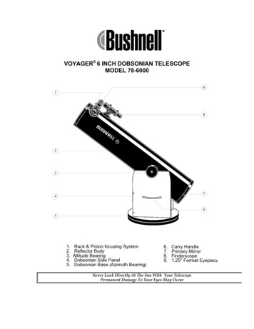
Figure 1.2. To remove the rear end ring, unthread the screwsthat connect it to the tube.3Feet attachment wood screws (length 1")5Encoder board mounting wood screws1Brass bushing1Azimuth axis hex-head screw (length 2.25")2Fender washers (diameter 1")1Hex lock nut4Altitude bearing cylinders4Altitude bearing cylinder screws (length 1.5", black)1Vertical stop knob1Small thin Azimuth Encoder board washer3Vertical stop knob washersBox #3 (XT12i only): Primary mirror and cellQty Description1Primary mirror1Mirror cell3Collimation knobs3Nylon washers3Springs2. AssemblyFigure 1.3. Place the three springs on the exposed threadedshafts of the mirror cell.Now that you have unpacked the boxes and familiarized yourself with all the parts in front of you, it’s time to begin assembly.The optics of the XT6i, XT8i, and XT10i are already installedinside the tube, so most of the required assembly concerns theDobsonian base. Skip to “Assembly of the Dobsonian Base.”For the XT12i, the primary mirror is shipped in a separate boxand will have to be installed in the optical tube. If you purchased the XT12i, start with the next paragraph for instructionson how to install the mirror into the tube.Assembly of the Optical Tube (XT12i only)In order to prevent damage to the primary mirror in shipment, itis shipped in its cell separately from the optical tube. To installthe mirror cell into the optical tube, the rear end ring attachedto the optical tube must first be removed. This is done byunthreading and removing the Phillips-head screws that connect the end ring to the tube (Figure 1.2), and then pulling theend ring off of the tube.Figure 1.4. Lower the rear end ring onto the mirror cell so thatthe threaded shafts pass through the end ring, and the end ringrests on the springs.4Warning: Once the rear end ring is removed from thetube, the raw edge of the tube itself will be exposed. Becareful not to cut or otherwise hurt yourself on the tube’sedge. Also be careful not to pinch your fingers whenattaching the assembled mirror cell onto the tube.Next, assemble the rear end ring to the mirror cell. Find aclean, flat surface, and turn the mirror cell over so that the mir-
Figure 1.6. Lower the assembled mirror cell onto the tube soFigure 1.5. Thread the collimation thumbnuts, with nylonwashers attached, through the rear end ring and onto thethreaded shafts. Make sure the thumbnuts have at least three fullturns of engagement on the shafts.one side of the end ring is seated on the tube edge. The threadedattachment holes in the end ring should also be lined up with thethrough holes in the end of the tube.ror is facing downwards. Place the three springs onto the threeexposed threaded shafts (Figure 1.3). Lower the end ring ontothe mirror cell so the threaded shafts pass through it, and theend ring rests on the springs (Figure 1.4). Add a nylon washer to each collimation knob and thread the collimation knobsthrough the end ring and onto the threaded shafts (Figure 1.5).Make sure the knobs have at least three full turns of engagement on the shafts. The mirror cell is now ready to be installedinto the tube.Assembling the SkyQuest XT12i IntelliScope mirror cell to thetube can be a bit tricky. This is because the large diameter andthin aluminum of the tube will cause the tube to become somewhat out of round once the rear end ring is removed.To assemble the mirror cell to the tube, stand the tube up vertically so that the raw edge of the tube is facing upward. Line upthe threaded holes in the edge of the mirror cell end ring withthe holes in the end of the tube. Then, lower the mirror cellonto the tube so that one side of the end ring is fully seatedonto the tube (Figure 1.6). Now, look along the perimeter of thetube, and you will notice a bulge in the tube that prevents themirror cell from fully seating on the tube (Figure 1.7). Positionyour body so that your chest is pressing against this bulge, andhug the telescope with your left hand so that the tube becomesround. With your right hand, gently tap down the side of themirror cell that needs to be seated, and the entire mirror cellshould seat onto the tube (Figure 1.8). Then replace the Phillips-head screws that connect the rear end ring to the tube.Assembly of the Dobsonian BaseRefer to Figure 2 during base assembly. The base need onlybe assembled once, unless you disassemble it for long-termstorage. The assembly process takes about 45 minutes andrequires, in addition to the supplied tools, a Phillips screw-Figure 1.7. Locate the area of tube that is bulging out andpreventing the mirror cell from fully seating.Figure 1.8. Hug the tube so that your chest pushes against thebulge, and a gentle tap should fully seat the mirror cell onto thetube.5
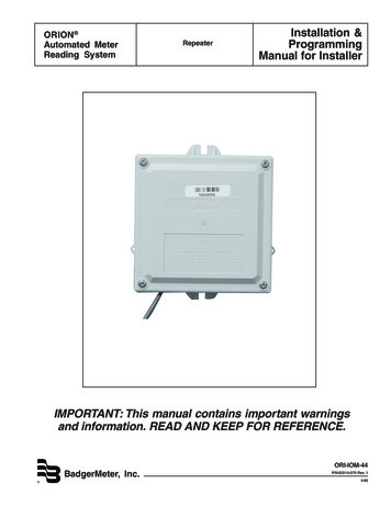
CNBSpacerwasherKLMFigure 3a. The spacer washer goes between the azimuthencoder board and the top baseplate of the Dobsonian base.DEFGJAEncoder boardmounting screwHIFigure 2. Exploded view of the XTi IntelliScope Dobsonian base.driver, and two adjustable crescent wrenches. You can substitute a 7/16" crescent wrench for one of the adjustable crescentwrenches, or use a pair of pliers.When tightening screws, tighten them until firm, but be carefulnot to strip the holes by over-tightening. If you use an electricscrewdriver, do final tightening with a standard screwdriver toavoid stripping.1. With a Phillips screwdriver, screw the plastic feet into theunderside of the ground baseplate (A) using the self-tapping wood screws provided. Insert the screws through thefeet and thread them into the predrilled starter holes.2. Loosely attach the front brace (B) to the two side panels(C) with six of the base assembly screws in the predrilledholes. Use the 4mm hex wrench to tighten the screws. Theside panels should be oriented so the SkyQuest IntelliScope labels are facing outward. The front brace should beoriented so the threaded insert is facing the interior of thebase. Do not completely tighten the screws yet.6Azimuth encoder boardFigure 3b. Installing the azimuth encoder board. Line up the largehole in the encoder board with the central hole in the top baseplate.3. Connect the two side panels (C) with the front braceattached to the top baseplate (D) with the remaining sixbase assembly screws in the predrilled holes. The side ofthe baseplate with the pilot hole near the square-shapedcutout should be facing downwards. Tighten all six screwsfirmly.4. Tighten the six side screws installed earlier.5. Attach the azimuth encoder board (E) to the underside ofthe top baseplate (D). Insert the encoder board mountingscrew through the circuit board and install the small spacerwasher (G) over the screw (Figure 3a). Insert the modularjack on the encoder board into the square-shaped hole inthe baseplate and align the encoder board so that the smallslotted hole in the board lines up with the predrilled starterhole, and the large hole lines up with the central hole in thebaseplate. Thread the encoder board mounting screw intothe predrilled starter hole with a Phillips screwdriver andtighten until just tight (Figure 3b).6. Place a fender washer (H) onto the azimuth axis screw (I).Then push the screw up through the hole in the groundbaseplate (A).Then slide the encoder disk (J), flat sidedown, onto the azimuth axis screw.
Correct Tension padsa.BearingcylindersFigure 5. Attaching the bearing cylinders.Encoderconnectorboardb.Figure 4. To connect the baseplates, tilt them only slightly, asshown. Do not place them on their side. (a) Use one wrench to holdthe hex nut steady (b) while turning the other end of the azimuthScrewsaxis screw.Figure 6. Attaching the encoder connector board.7. Place the brass bushing (F) onto the azimuth axis screw (I)so that the wide end of the bushing is closest to the encoderdisk (J). Seat the bushing onto the encoder disk so that theregistration feature on the bushing goes into the hole inthe encoder disk. You may need to move the encoder diskaround on the azimuth axis screw a bit for the bushing toseat properly.10. Attach the handle (M) to the front brace (B) with the twohandle mounting hex-head screws. Place one washer oneach screw, then press the handle against the front brace(the end of the handle bearing the Orion logo should be up).Then thread the screws from the inside of the base into thehandle until tight using the supplied crescent wrench.8. Carefully position the top baseplate (D) over the groundbaseplate (A) and lower it so the brass bushing (F) goesinto in the center hole of the top baseplate. Place theremaining fender washer (K) onto the shaft of the azimuthaxis screw, then thread the hex lock nut (L) onto the end ofthe azimuth axis screw and tighten it finger tight, for now.9. To tighten the azimuth axis screw (I) and hex lock nut (L),tilt the assembled Dobsonian base at a slight angle to liftthe ground baseplate off the ground. Now, with one wrench(or pliers) hold the head of the azimuth axis screw still whileturning the hex lock nut with the other wrench. Figure 4shows this being done. Tighten the hex lock nut just untilthe top fender washer is no longer moving freely, thentighten the hex nut a quarter turn beyond that. This ensuresproper spacing between the encoder disk and the azimuthencoder board.11. Line up one of the altitude bearing cylinders (N) with theinside of one of the four bearing cylinder holes on the sidepanels. Push a bearing cylinder screw through the sidepanel and thread the bearing cylinder onto it (Figure 5).The beveled end of the cylinder should be farthest from theside panel. You can tighten the cylinder by hand or, if needed, with the supplied 4mm hex key. Repeat for the remaining three bearing cylinders.12. Attach the encoder connector board to the side panel.Place the board against the side panel so that the modularjack fits into the square-shaped hole and thread four encoder board mounting screws through the connector board andinto the predrilled holes in the side panel until tight (Figure6).Next, you’ll need to install the altitude encoder board assembly.To do so, please refer to the separate instruction manual for theIntelliScope Computerized Object Locator.7
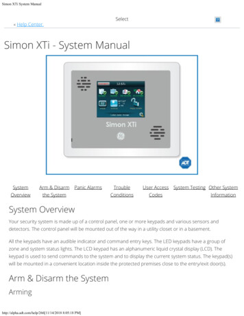
Installing the Vertical StopPlace three flat washers onto the shaft of the vertical stopscrew. Thread the vertical stop into the threaded insert on theinside of the front panel until just tight (Figure 7). The positionof the vertical stop is adjustable by adding or removing washers. This is important when using the IntelliScope Computerized Object Locator, since the optical tube must be exactly vertical before commencing with the two-star alignment procedure(described later). For precise adjustment of the vertical stop,see the manual for the Computerized Object Locator.Installing the Eyepiece RackThe aluminum eyepiece rack is a standard accessory on SkyQuest IntelliScope Dobsonians. It holds three 1.25" eyepiecesand one 2" eyepiece (three 1.25" eyepieces on the XT6i) in aconvenient place on the base, within easy reach while you’reobserving. An optional 1.25" barlow lens also can be held inthe rack. A few inches down from the top of the front bracepanel you will notice two predrilled starter holes, about 6" apart.Thread the black wood screws into the starter holes with a Phillips screwdriver. Then you can “keyhole” the eyepiece rackonto the wood screws and continue tightening the screws (Figure 8). If you want to be able to remove the racklater withoutusing a screwdriver, do not tighten the screws too tightly. Becertain that the screws are loose enough that you can lift therack and remove it from the screws through the larger opening of the keyhole. If you want to have the rack permanentlyattached, tighten the screws. You may find it easier to carry thebase by the handle if the eyepiece rack is removed.Placing the Optical Tube on the Dobsonian BaseLift the optical tube and gently place it into the Dobsonian baseso that the altitude bearings on either side of the tube rest onthe bearing cylinders. Orient the optical tube as shown in Figure 9. Make certain that the optical tube does not get hungup on the vertical bumper stop or the CorrecTension pads asyou put it in place. Be careful when placing the tube on thebearings, since if it is inserted at the wrong angle the hub canstrike the encoder connector board and potentially damage it.Once on the bearing cylinders, the tube should pivot freely upand down with gentle hand pressure. Note that the tube will notyet be properly balanced, since the eyepiece and finder scopeare not in place, and the CorrecTension system has not beeninstalled.Installing the CorrecTension FrictionOptimization SystemAn exciting feature of the SkyQuest IntelliScope Dobsonians isthe redesigned CorrecTension (XT) system. Because of theirrelatively light weight, smaller Dobsonians (under 16") havealways been plagued by insufficient friction on the altitudebearing surfaces. As a result, such telescopes move up anddown much too freely. This causes problems when the observer tries to accurately center and track an object for viewing,especially at higher powers. Also, the telescope becomes very8Vertical StopFigure 7. The vertical stopFigure 8. Using the two supplied wood screws, install thealuminum eyepiece rack in the predrilled holes near the top of thefront panel.sensitive to balance, requiring additional equipment such ascounterweight systems or springs to compensate.SkyQuest IntelliScope Dobsonians employ a simple yet effective remedy for the friction problem that obviates the need forsuch cumbersome countermeasures. CorrecTension FrictionOptimization utilizes a simple “disc brake” to apply the correctlevel of tension to the altitude bearings. With the XT system,you can change eyepieces or add a barlow lens without havingto tediously adjust the telescope’s balance as you would withother Dobsonians. The altitude friction can be made equal tothe azimuth friction, ensuring optimal navigation motion.To install the XT system, follow these steps while referring toFigures 10 and 11:1. Select one of the retaining/tensioning knobs and slide themetal washer onto the shaft, followed by the white nylonwasher (you will need to thread this washer onto the shaft).This knob will now be known as the tensioning knob. Push
Figure 10. The tensioning knob, with the metal and nylonAltitudebearingswashers, goes on the left side of the base, just above theIntelliScope port. The tensioning knob should be tightened until theCorrecTension pads just touch the telescope’s altitude bearing.BearingcylindersFigure 9. Lift the optical tube and place it into the Dobsonianbase so that the altitude bearings rest on the bearing cylinders.Orient the optical tube as shown. Do not bump the encoderconnector board or vertical stop when installing the optical tube.the shaft of the tensioning knob through the hole in theleft side panel (the one that has the IntellisScope port)(Figure 10). Thread the knob into the altitude bearing untilthe CorrecTension pads on the interior surface of the sidepanel just touch the altitude bearing on the optical tube.2. Thread the other retaining/tensioning knob, which we’llnow refer to as just the retaining knob, through the altitude encoder’s aluminum shaft and thread it into the opticaltube’s right side bearing (Figure 11). Make sure this knob isfully tightened.Figure 11. The retaining knob on the right side of the baseis inserted though the aluminum shaft of the altitude encoderassembly.Note: Only the left side panel has a white nylon bushingin the hole for the tensioning knob. The right side paneldoes not require this bushing.The CorrecTension system is now installed. If you wish toremove the optical tube from the base, you will first need tounthread and remove both the knobs. Once the optical tube isremoved from the base, thread the knobs back into the altitudebearings so you do not lose them.Installing the Finder ScopeSkyQuest IntelliScope Dobsonians come with a high-quality,large-aperture 9x50 (6x30 for the XT6) right-angle correct-9
Objectivelens cellNylonalignmentthumbscrewFinder scope (2)bracketEyepiece2" eyepiece adapter1.25" eyepiece adapterFocus knobsFocus lockthumbscrewFocusinglock ringCorrect-Imageprism housingTensionerFigure 12a. The 9x50 right-angle correct-image finder scopeFocusing tensionadjustment set screwFigure 13a. The 2" Crayford focuser of the SkyQuest XT8i,XT10i, and XT12i.and bracket (6x30 for the XT6i).Focus knobsFocus lockthumbscrewKnurled thumbscrewFocusing tensionadjustment set screwsFinder scope bracketDovetail holderFigure 12b. Inserting the finder scope into its dovetail holder.image (RACI) achromatic crosshair finder scope (Figure 12a)as standard equipment. This greatly aids in finding objects toview in the night sky.The finder scope arrives pre-installed in its bracket, but mustbe placed into the dovetail holder on the telescope tube. Insertthe base of the finder scope into the dovetail holder locatedadjacent to the focuser (Figure 12b). Lock the bracket intoposition by tightening the knurled thumbscrew on the dovetailholder.Inserting an EyepieceThe final step in the assembly process is to insert an eyepieceinto the telescope’s focuser. First, take the cover cap off thefocuser drawtube.For the XT8i, XT10i, and XT12i: Loosen the thumbscrew onthe 1.25" eyepiece adapter (Figure 13a). Do not loosen thetwo thumbscrews on the 2" eyepiece adapter. Insert the supplied 25mm Sirius Plössl eyepiece, then secure it by retighten-10Figure 13b. The 1.25" rack-and-pinion focuser of the SkyQuestXT6i.ing the thumbscrew on the 1.25" eyepiece adapter. The othereyepiece can be placed in the eyepiece rack until it is needed.For the XT6i: Loosen the two thumbscrews on the eyepieceholder and insert the 25mm Sirius Plössl eyepiece. Thensecure it in place with the thumbscrews (Figure 13b). Theother eyepiece can be placed in the eyepiece rack until it isneeded.The basic assembly of your SkyQuest IntelliScope Dobsonianis now complete. It should appear as shown in Figure 1. Thedust cap on the front of the telescope tube should alwaysremain in place when the telescope is not in use. It is alsoa good idea to store eyepieces in an eyepiece case and toreplace the cover caps on the focuser and finder scope whenthe telescope is idle.
AltitudeAzimuthFigure 14. The SkyQuest IntelliScope has two axes of motion;altitude (up/down) and azimuth (left/right).3. Using Your TelescopeOne of the great benefits of the SkyQuest XTi IntelliScopeDobsonian is its ability to point to more than 14,000 celestial objects via the IntelliScope Computerized Object Locator (Controller). This functionality will greatly enhance yourobserving experience by enabling you to quickly and preciselylocate even very faint objects. For more about IntelliScopeController functionality, see Section 6.Before using your IntelliScope for the first time at night, we recommend getting a feel for its basic functions during daylighthours. Find a spot outdoors where you have a clear view ofsome object or landmark that is at least 1/4-mile away. It is notcritical that the base be exactly level, but it should be placed onsomewhat flat ground or pavement to ensure smooth movement of the telescope.Remember, never point the telescope at or near the Sun without using a proper solar filter over the front aperture!Altitude and Azimuth MotionThe SkyQuest’s Dobsonian base permits smooth motion ofthe telescope along two axes: altitude (up/down) and azimuth(left/right) (Figure 14). For altitude motion, the altitude bearings on the telescope tube glide on pairs of bearing cylindersmade from ultra-high molecular weight (UHMW) polyethylene.For azimuth motion, the top baseplate moves on three PTFE/UHMW bearing pads affixed to the ground baseplate.To move the telescope, simply take hold of the navigation knobnear the front opening of the scope and gently move the tubeup or down and left or right as desired. Both motions can bemade simultaneously and in a continuous manner for easyaiming. When the telescope is pointed high in altitude, rotatingthe tube in azimuth can cause the base to “tip” because of thereduced leverage. In this case it is helpful to place your otherhand on the base or the optical tube to help “guide” it.Figure 15. Adjust the tensioning knob until the altitude balanceis just right. The telescope should move easily in altitude withoutdrifting when you let go.Setting the Altitude Tension LevelThe telescope should move smoothly with just gentle handpressure. While azimuth friction is not adjustable, the altitudefriction can be adjusted to the desired level by turning the altitude tensioning knob (Figure 10). Note that the altitude tensioning knob is the one just above the IntelliScope ControllerPort. The knob on the opposite (right) side of the base is merely a retaining knob; it does not affect altitude tension.Adjustable tension is a feature of the IntelliScopes’ exclusive springless CorrecTension Friction Optimization system.CorrecTension adds just the right amount of friction to keep thetelescope tube in proper balance, even when other accessories are added on, such as a barlow lens or a heavier eyepiece.A good way to set the altitude tension is to point the telescope atabout a 45 angle with the eyepiece and finder scope removed.Loosen the altitude tension knob until the front of the opticaltube starts to drift upward. As it does so, tighten the tensionknob just enough to make the tube stop drifting (Figure 15).When the eyepiece and finder scope are replaced, the motionshould be ideal – not too stiff, not too loose.You will want to be able to “track” the motion of celestial objectswhile viewing them by making small movements of the telescope without experiencing jerking (too much tension) or overshooting of the desired position (too little tension).Focusing the TelescopeWith the 25mm Sirius Plössl eyepiece in the focuser andsecured with the thumbscrew(s), move the telescope so thefront (open) end is pointing in the general direction of an objectat least 1/4-mile away. Now, with your fingers, slowly rotate oneof the focusing knobs until the object comes into sharp focus.Go a little bit beyond sharp focus until the image just starts toblur again, then reverse the rotation of the knob, just to makesure you’ve hit the exact focus point.11
If you have trouble focusing, rotate the focusing knob so thedrawtube is in as far as it will go. Now look through the eyepiece while slowly rotating the focusing knob in the oppositedirection. You should soon see the point at which focus isreached.For XT8i, XT10i and XT12i models, the focus lock thumbscrew on the bottom of the focuser body (Figure 13a) will lockthe focuser drawtube in place once the telescope is properlyfocused. The XT6i’s focus lock thumb screw is located on thetop of the focuser body (Figure 13b). Before focusing, remember to first loosen the focus lock thumb screw. Do not loosenthe thumb screw too much as there must be some tension tokeep the drawtube secure within the focuser.If you find the drawtube tension when focusing is either tootight (focus knob is difficult to turn) or too loose (image shiftswhen focusing or drawtube moves inward by itself), the tension can be adjusted for optimal performance. On the XT8i,XT10i, and XT12i, the focusing tension adjustment set screwis a 3mm socket head set screw located below the focus lockthumb screw (Figure 13a). A 3mm hex key is required foradjustment of focus tension. On the XT6i, the focusing tensionadjustment set screws are the two small set screws locatedon either side of the focus lock thumb screw (Figure 13b). A1.5mm hex key is required to adjust the focus tension on theXT6i. Due to the rack-and-pinion focuser design on the XT6,tension adjustment should not normally be needed as it hasbeen pre-adjusted at the factory.Viewing with EyeglassesIf you wear eyeglasses, you may be able to keep them on whileyou observe, if your eyepieces have enough eye relief to allowyou to see the whole field of view. You can try this by looking through the eyepiece first with your glasses on and thenwith them off, and see if the glasses restrict the view to only aportion of the full field. If they do, you can easily observe withyour glasses off by just refocusing the telescope the neededamount. If you suffer from severe astigmatism, however, youmay find images noticeably sharper with your glasses on.Aligning the Finder ScopeThe finder scope must be aligned accurately with the telescopefor proper use. To align it, first aim the main telescope in thegeneral direction of an object at least 1/4-mile away, e.g., thetop of a telephone pole, a chimney, etc. Position that object inthe center of the telescope’s eyepiece.The finder scope uses a spring-loaded bracket that makesalignment of the finderscope very easy. As you turn either of thethumbscrews, the spring in the bracket’s tensioning pin movesin and out to keep the finder scope secure in the bracket.Note: The image in the main telescope will appearupside-down (rotated 180 ). This is normal for reflectortelescopes (see Figure 16).Now look thro
Please read these instructions thoroughly before beginning assembly and subsequent use of the telescope. 1. Unpacking The telescope is packed in two boxes (three for the XT12i), one containing the optical tube assembly and accessories, the other containing the unassembled Dobsonian base (the third box for the XT12i includes the mirror and cell).