Transcription
ECEN720: High-Speed LinksCircuits and SystemsSpring 2014Lecture 8: RX FIR, CTLE, & DFE EqualizationSam PalermoAnalog & Mixed-Signal CenterTexas A&M University
Agenda RX FIR Equalization RX CTLE Equalization RX DFE Equalization RX equalization papers posted on thewebsite2
Link with EqualizationSerializerDTX[N:0]ChannelΣTX ClkGeneration(PLL)fDeserializerRX CTLE DFEEqualizationTX FIREqualizationDRX[N:0]RX ClkRecovery(CDR/Fwd Clk)3
TX FIR Equalization TX FIR filter pre-distorts transmitted pulse in order to invert channeldistortion at the cost of attenuated transmit signal (de-emphasis)w-1TXdataz-1w0z-1w1z-1w2z-1wn4
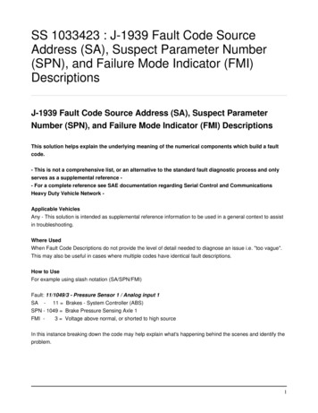
RX FIR Equalization Delay analog input signal andmultiply by equalizationcoefficients Pros With sufficient dynamic range, canamplify high frequency content(rather than attenuate lowfrequencies) Can cancel ISI in pre-cursor andbeyond filter span Filter tap coefficients can beadaptively tuned without anyback-channel Cons Amplifies noise/crosstalk Implementation of analog delays Tap precision[Hall]5
RX Equalization Noise Enhancement Linear RX equalizers don’t discriminate betweensignal, noise, and cross-talk While signal-to-distortion (ISI) ratio is improved, SNRremains unchanged[Hall]6
Analog RX FIR Equalization Example 5-tap equalizer with tap spacing of Tb/23rd-order delay cell1Gb/s experimental resultsD. Hernandez-Garduno and J. Silva-Martinez, “A CMOS 1Gb/s 5-Tap Transversal Equalizer based on 3rd-Order Delay Cells,"ISSCC, 2007.7
Digital RX FIR Equalization Digitize the input signal with high-speed low/mediumresolution ADC and perform equalization in digital domain Digital delays, multipliers, adders Limited to ADC resolution Power can be high due to very fast ADC and digital filters[Hanumolu]8
Digital RX FIR Equalization Example[Harwood ISSCC 2007] 12.5GS/s 4.5-bit Flash ADC in 65nm CMOS 2-tap FFE & 5-tap DFE XCVR power (inc. TX) 330mW, Analog 245mW, Digital 85mW9
Link with EqualizationSerializerDTX[N:0]ChannelΣTX ClkGeneration(PLL)fDeserializerRX CTLE DFEEqualizationTX FIREqualizationDRX[N:0]RX ClkRecovery(CDR/Fwd Clk)10
RX Continuous-Time Linear Equalizer (CTLE) Passive R-C (or L) can implementhigh-pass transfer function tocompensate for channel loss Cancel both precursor and long-tailISI Can be purely passive or combinedwith an amplifier to provide gainPassive CTLEActive CTLEVo [Hanumolu]Din-VoDin 11
Passive CTLE Passive structures offer excellent linearity,but no gain at Nyquist frequencyH (s ) ωz [Hanumolu]1 R1C1sR2R1 R2 1 R1 R2 (C C )s12R1 R21,R1C1DC gain Peaking ωp 1R1 R2(C1 C2 )R1 R2R2C1, HF gain R1 R2C1 C2HF gain ω p R1 R2 C1 R2 C1 C2DC gain ω z12
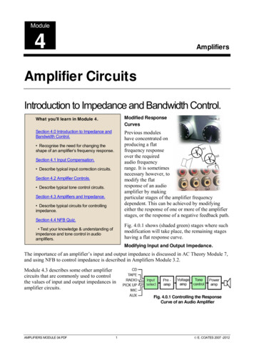
Active CTLE Input amplifier with RCdegeneration can providefrequency peaking with gainat Nyquist frequency Potentially limited by gainbandwidth of amplifier Amplifier must be designedfor input linear range Often TX eq. provides somelow frequency attenuation Sensitive to PVT variationsand can be hard to tune Generally limited to 1st-ordercompensation[Gondi JSSC 2007]1gRS CSH (s ) mC p 1 g m RS 2 1 s s RS CS RD C p 1 g m RS 211, ωp1 , ωp2 ωz RS CSRS CSRD C ps DC gain g m RD, Ideal peak gain g m RD1 g m RS 2Ideal Peaking Ideal peak gain ω p1 1 g m RS 2DC gainωz13
Active CTLE ExampleVo Din-VoDin 14
Active CTLE Tuning Tune degeneration resistor and capacitor to adjust zerofrequency and 1st pole which sets peaking and DC gainCS Increasing CS moves zero and1st pole to a lower frequencyw/o impacting (ideal) peaking Increasing RS moves zero tolower frequency and increasespeaking (lowers DC gain) Minimal impact on 1st poleRSωz 1 g m RS 21, ωp1 RS CSRS CS15
Link with EqualizationSerializerDTX[N:0]ChannelΣTX ClkGeneration(PLL)fDeserializerRX CTLE DFEEqualizationTX FIREqualizationDRX[N:0]RX ClkRecovery(CDR/Fwd Clk)16
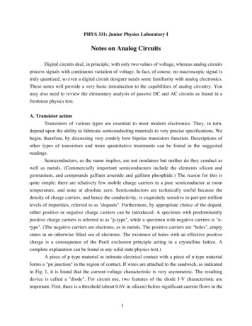
RX Decision Feedback Equalization (DFE) DFE is a non-linearequalizer z k yk w1 d k 1 wn 1 d k (n 1) wn d k n Slicer makes a symboldecision, i.e.quantizes input ISI is then directlysubtracted from theincoming signal via afeedback FIR filter17
RX Decision Feedback Equalization (DFE) Pros Can boost high frequencycontent without noise andcrosstalk amplification Filter tap coefficients can beadaptively tuned without anyback-channel z k yk w1 d k 1 wn 1 d k (n 1) wn d k n Cons Cannot cancel pre-cursor ISI Chance for error propagation Low in practical links (BER 10-12) Critical feedback timing path Timing of ISI subtractioncomplicates CDR phasedetection[Payne]18
DFE Example If only DFE equalization, DFE tap coefficientsshould equal the unequalized channel pulseresponse values [a1 a2 an] With other equalization, DFE tap coefficientsshould equal the pre-DFE pulse response values DFE provides flexibility in the optimization of otherequalizer circuitsi.e., you can optimize a TX equalizer without caringabout the ISI terms that the DFE will take care of[w1 w2] [a1 a2]a1a219
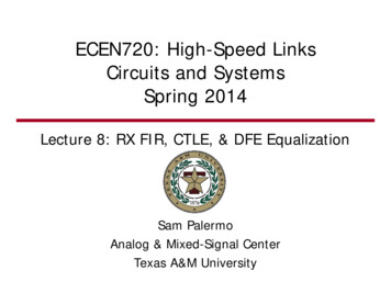
Direct Feedback DFE Example (TI)to P4TAP3RXEQTAP2A1TAP1RXINLatchto demuxVDDA2 ½ rate architecture Adaptive tap algorithm Closes timing on 1sttap in ½ UI forconvergence of bothadaptive equalizationtap values and CDRA2 6.25Gb/s 4-tap DFE TAP1: 5 bits TAP2: 4 bits sign TAP3,4: 3 bits signLatchFeedback tap muxR. Payne et al, “A 6.25-Gb/s Binary Transceiver in 0.13-um CMOS for Serial Data Transmission Across High LossLegacy Backplane Channels,” JSSC, vol. 40, no. 12, Dec. 2005, pp. 2646-265720
Direct Feedback DFE Critical PathtCLKQSAD0A2A1RXINtPROPA2RXEQTIME 1UICLK90t PROPMUXRXEQ[Payne]1UICLK90tCLK QSA t PROPMUX t PROPA2 1UI Must resolve data and feedback in 1 bit period TI design actually does this in ½UI for CDR21
DFE Loop Unrollingdk dk-1 1dk-1ykdk dk-1 -1[Stojanovic] Instead of feeding back andsubtracting ISI in 1UI Unroll loop and pre-compute 2possibilities (1-tap DFE) withadjustable slicer thresholddk dk-1 1α w1 With increasing tap number,comparator number grows as 2#tapsdk dk-1 -1 sgn ( yk w1 ) " if" d k 1 1dk sgn ( yk w1 ) " if" d k 1 1 22
DFE Resistive-Load Summer[Park]Summer Swing IR, τ RC Summer performance is critical for DFE operation Summer must settle within a certain level of accuracy( 95%) for ISI cancellation Trade-off between summer output swing and settling time Can result in large bias currents for input and taps23
DFE Integrating Summer[Park ISSCC 2007] Integrating current onto load capacitances eliminates RC settling time Since T/C R, bias current can be reduced for a given output swing Typically a 3x bias current reduction24
Digital RX FIR & DFE Equalization Example[Harwood ISSCC 2007] 12.5GS/s 4.5-bit Flash ADC in 65nm CMOS 2-tap FFE & 5-tap DFE XCVR power (inc. TX) 330mW, Analog 245mW, Digital 85mW25
DFE with Feedback FIR Filter[Liu ISSCC 2009] DFE with 2-tap FIR filter in feedback willonly cancel ISI of the first two post-cursors26
“Smooth” ChannelH 2e tτ[Liu ISSCC 2009] A DFE with FIR feedback requires many taps to cancel ISI Smooth channel long-tail ISI can be approximated asexponentially decaying Examples include on-chip wires and silicon carrier wires27
DFE with IIR Feedback[Liu ISSCC 2009] Large 1st post-cursor H1 is canceled with normal FIRfeedback tap Smooth long tail ISI from 2nd post-cursor and beyond iscanceled with low-pass IIR feedback filter Note: channel needs to be smooth (not many reflections) inorder for this approach to work well28
DFE with IIR Feedback RX Architecture[Liu ISSCC 2009]29
Merged Summer & Partial Slicer[Liu ISSCC 2009] Integrating summer with regeneration PMOS devices torealize partial slicer operation30
Merged Mux & IIR Filter[Liu ISSCC 2009] Low-pass response (time constant) implemented by RD and CD Amplitude controlled by RD and ID 2 UI delay implemented through mux to begin cancellation at 2ndpost-cursor31
Advanced Modulation In order to remove ISI, we attempt toequalize or flatten the channel responseout to the Nyquist frequency For less frequency-dependent loss, movethe Nyquist frequency to a lower value viamore advance modulation 4-PAM (or higher) Duo-binary Refer to lecture 4 for more details32
Multi-tone Signaling2 Quarature10Gb/s duo-binary10Gb/s duo-binary30Gb/s total![Beyene AdvPack 2008] Instead equalizing out to baseband Nyquist frequencyDivide the channel into bands with less frequency-dependent lossShould result in less equalization complexity for each sub-bandRequires up/down-conversionDiscrete Multi-tone used in DSL modems with very challengingchannels Lower data rates allow for high performance DSP High-speed links don’t have this option (yet)33
Next Time Link Noise and BER Analysis34
Direct Feedback DFE Example (TI) 6.25Gb/s 4-tap DFE ½ rate architecture Adaptive tap algorithm Closes timing on 1st tap in . ½ UI . for convergence of both adaptive equalization tap values and CDR. TAP 1. Latch Latch Latch. TAP 2 TAP 4 TAP 3. Latch Latch Latch. A 2 A 2 VDD. RXEQ RXIN CLK0/180 CLK90/270 DFECLK to demux to demux .