Transcription
MiVoice MX-ONERoutes Administration, Operational DirectionsRelease 7.2September 24, 2019
NoticeThe information contained in this document is believed to be accurate in all respects but is not warranted by Mitel Networks Corporation (MITEL ). The information is subject to change without notice and should not be construed in any way as a commitment by Mitel or any of its affiliates or subsidiaries. Mitel and its affiliates and subsidiaries assume no responsibility for any errorsor omissions in this document. Revisions of this document or new editions of it may be issued to incorporate such changes.Nopart of this document can be reproduced or transmitted in any form or by any means - electronic or mechanical - for any purposewithout written permission from Mitel Networks Corporation.TrademarksThe trademarks, service marks, logos and graphics (collectively “Trademarks”) appearing on Mitel's Internet sites or in its publications are registered and unregistered trademarks of Mitel Networks Corporation (MNC) or its subsidiaries (collectively "Mitel")or others. Use of the Trademarks is prohibited without the express consent from Mitel. Please contact our legal department atlegal@mitel.com for additional information. For a list of the worldwide Mitel Networks Corporation registered trademarks, pleaserefer to the website: http://www.mitel.com/trademarks. , Trademark of Mitel Networks Corporation Copyright 2019, Mitel Networks CorporationAll rights reserved
ContentsChapter: 1General . . . . . . . . . . . . . . . . . . . . . . . . . . . . . . . . . . . . 1Chapter: 2Glossary . . . . . . . . . . . . . . . . . . . . . . . . . . . . . . . . . . . 2Definitions and Terminology . . . . . . . . . . . . . . . . . . . . . . . . . 2Chapter: 3Basic Signaling . . . . . . . . . . . . . . .CAS and CCS . . . . . . . . . . . . . . . . .CAS - Channel Associated SignalingCCS - Common Channel Signaling .Line and Register Signaling . . . . . . . . .Example of Signaling . . . . . . . . . . . . . . . . . . . . . . . . . . . . . .666677Chapter: 4Prerequisite . . . . . . . . . .Tools . . . . . . . . . . . . . . .References . . . . . . . . . . . .Execution - Routing, General . . . . . . . . . . . . . . . . . .9999Chapter: 5Tools . . . . . . . . . . . . . . . . . . . . . . . . . . . . . . . . . . . . 10Chapter: 6References . . . . . . . . . . . . . . . . . . . . . . . . . . . . . . . . . 11Chapter: 7Execution . . . . . . . . . . . . . . . .Routing, General . . . . . . . . . . . .Routing, CCSS7 . . . . . . . . . . . . .Basic Routing . . . . . . . . . . . . . .Extended Services for Outgoing TrafficA-number Request from Public ISDN .Prerequisites . . . . . . . . . .Execution . . . . . . . . . . . .A-Subscriber Charging . . . . . . . . .2/154 31-ANF 901 14 Uen J 2019-10-18. . . 12. . . .12. . . .13. . . .14. . . .16. . . .17. . . .17. . . .17. . . .17
Prerequisites . . . . . . . . . . . . . . . . . . . . . . . . . . . . .17Execution . . . . . . . . . . . . . . . . . . . . . . . . . . . . . . .17Chapter: 8DISA - Direct Inward System Access . . . . . . . .Execution . . . . . . . . . . . . . . . . . . . . . . .Example with DID external lines or tie linesExample with manual external lines . . . . . . 18. . . .18. . . .18. . . .19Chapter: 9ERWT - Expensive Route Warning TonePrerequisites . . . . . . . . . . . . . . .Execution . . . . . . . . . . . . . . . . .ENT - External Number Table . .NLT - Number Length Table . . .DNT - Destination Number Table. . . 21. . . .21. . . .21. . . .21. . . .23. . . .25Chapter: 10IDNX Interworking . . . . . . . . . . . . . . . . . . . . . . . . . . . . . 29Chapter: 11LCR - Least Cost Routing . . . . . . . . . . . . . . . . . . . . . . . . . . 30Prerequisites . . . . . . . . . . . . . . . . . . . . . . . . . . . . . . . . .32Chapter: 12Loop Avoidance/Transit Counter . . . . . . . . . . . . . . . . . . . . . 33Prerequisite . . . . . . . . . . . . . . . . . . . . . . . . . . . . . . . . . .33Execution . . . . . . . . . . . . . . . . . . . . . . . . . . . . . . . . . . .33Chapter: 13PNR - Private Network Routing . . . . . . . . . . . . . . . .Prerequisites . . . . . . . . . . . . . . . . . . . . . . . . . .Execution . . . . . . . . . . . . . . . . . . . . . . . . . . . .Example 1, Initiation of a Tie Line Route . . . . . . .Example 2, Initiation of an Alternative Route . . . .Example 3, Initiation of a Second Alternative RouteChapter: 14Name on Route . . . . . . . . . . . . . . . . . . . . . . . . . . . . . . 45Prerequisites . . . . . . . . . . . . . . . . . . . . . . . . . . . . . . . . .45Execution . . . . . . . . . . . . . . . . . . . . . . . . . . . . . . . . . . .45Chapter: 15Incoming SIP Route Settings when WebRTC is Used in Client/Gateway 46Chapter: 16Termination . . . . . . . . . . . . . . . . . . . . . . . . . . . . . . . . 472/154 31-ANF 901 14 Uen J 2019-10-18. . . 34. . . .38. . . .38. . . .38. . . .40. . . .42
CHAPTER 1GENERALGeneralThese operational directions give a summarized overview description of the administration of routes. (Thesame, and more detailed, information can be found in the different referred operational directions.)The first part of the document consists of definitions and explanations of the used terminology. Thesecond part explains the fundamentals of signaling and routing. The last part explains how to organizeand set up routes, and special route applications in general.External lines are used to connect an MX-ONE with other exchanges, both private (PBX) and publicexchanges. External lines with identical characteristics, signaling and direction together form a route.This document deals with both digital and analog external lines. It also mentions different ways ofsignaling over an external line. Signaling is the way the exchanges communicate with each other.2/154 31-ANF 901 14 Uen J 2019-10-181
CHAPTER 2DEFINITIONS AND TERMINOLOGYGLOSSARYGlossaryFor a complete list of abbreviations and glossary, see the description for ACRONYMS, ABBREVIATIONSAND GLOSSARY.Definitions and TerminologyAlternative RoutingBy alternative routing it is possible to reach an external destination via different routes. A primary choiceroute can have several alternative routes to reach the external destination.If the primary route is not available, the system tries to use the first alternative route and so on. If necessary the system will modify the dialed number (add predigits or delete dialed digits or both) to suite thenumber to the numbering plan used in the exchange at the other end of the alternative route.NOTE: In order to fully utilize the system’s netservice capability, alternative routes that support netservicesshould be initiated as the first choice to the primary route. The requested service will fail if an alternativeroute not supporting netservices is used. Use the routes that do not support netservices as last alternativeroute choices.B-ChannelA 64 kbit/s channel is used in ISDN for transmitting digitally coded speech and data. It is used for circuitswitched connections, packet switched connections, and semipermanent connections.To form an interface, a signaling channel is also needed. A common interface is the 30B D interface. Itconsists of thirty B-channels for speech or data and one D-channel for signaling.BC - Bearer CapabilityThe bearer capability is set for each outgoing route when initiated. It states the type of calls the line iscapable of transmitting, and depends on the bandwidth of the line, if compression is used, and so on.The bearer capability of a route is set to one or more of the following type of calls: 3.1 kHz Audio. Telephony or data calls with modem. Speech. Telephony calls only. 7 kHz, high quality speech (for example used for sports commentators). 64 kbit/s Unrestricted digital channel (64K-C). Modemless data calls. Also called 64 kbit/s Clearchannel (hence the C in 64K-C). 64 kbit/s Restricted digital channel (64K-R). Modemless data calls, US market. 16 kbit/s Unrestricted digital channel. Compressed voice calls and 16 kbit/s subrate data.In the same way as for the routes, each initiated extension will have a bearer category set. When anexternal call from an extension is made, a request for an external line with matching bearer capability ismade. If there is no such line available the call will be rejected.If the call is transited over an exchange and onto another external line a matching bearer capability (if itis known) is requested again.The requested bearer capability is part of the protocol for signaling systems based on Message OrientedSignaling. On CAS systems no information of requested bearer capability is transferred.2/154 31-ANF 901 14 Uen J 2019-10-182
CHAPTER 2DEFINITIONS AND TERMINOLOGYGLOSSARYCall MeteringThe possibility to detect and store call metering (charging) pulses from the public exchange on anoutgoing call. As there are many standards for the conveyance of the pulses, different call meteringboards (CDUs for 50 Hz, 12 kHz and 16 kHz) are available for analog trunks. There is also the possibilityto have call metering equipment directly on the trunk line board.NOTE: There are two types of call metering boards; detection boards and the optional filter boards. Also,since one call metering board only can handle a given number of external lines, a number of boards maybe necessary.CAS - Channel Associated SignalingThe traditional method of signaling between two exchanges. The signals necessary for the traffic carriedby a channel, are transmitted in the channel itself or in a channel permanently associated with it. In otherwords: Speech and signals travel together.CCS - Common Channel SignalingA method of signaling between two exchanges. Signals relating to a number of channels are transmittedover a single data link, in addressed messages. In other words: Speech and signals travel independently,both in time and media.CCSS7 - Common Channel Signaling System No. 7The overall objective of CCSS7 is to provide an internationally standardized general purpose commonchannel signaling system, optimized for operation in public digital telecommunication networks inconjunction with stored program controlled exchanges.CCSS7 is a common channel signaling system defined for 64 kbit/s operation between exchanges. Thesignaling system uses signaling links for transfer of signaling messages between exchanges or othernodes in the telecommunication network served by the system. The system is normally applied withredundancy of signaling links and it includes functions for automatic diversion of signaling traffic to alternative paths in case of link failure. The capacity and reliability for signaling may thus be dimensioned byprovision of a multiplicity of signaling links according to the requirements of each application.ChargingThe same as call metering, see above.CO - Central OfficeAn exchange in the PSTN. Another name often used is PE (Public Exchange).CSI - Call Service InformationCSI is used for similar reasons as FRL/TCM.D-ChannelA 16 or 64 kbit/s channel used in ISDN for signaling, mainly signaling for circuit switched connections.The D-channel itself uses packet switching. When it is not used for signaling it can be used for packetswitched data traffic.DID - Direct In DialingDirect In Dialing enables subscribers in the public network to dial a PBX extension directly, that is, withoutassistance from the PBX operator.Another term for this feature is DDI, Direct Dialing In.DISA - Direct Inward System Access2/154 31-ANF 901 14 Uen J 2019-10-183
CHAPTER 2DEFINITIONS AND TERMINOLOGYGLOSSARYEnables authorized users to call in to a PBX and get access to the PBX’s services, except those servicesthat require a procedure.DISA calls can be established via direct in dialing external lines or via manual external lines (central officeexternal lines).DPC - Destination Point CodeThe destination point code is the part of the label in a CCSS7 signaling message which uniquely identifiesthe signaling point to which the message is finally addressed.DPNSS - Digital Private Network Signaling SystemDPNSS is a signaling system designed to extend services available for extensions in a single PBX toextensions in other PBX exchanges in a private network. To the user the whole private network willbehave like one PBX regarding services.DPNSS utilize digital external lines and common channel signaling (CCS).DTMF - Dual Tone Multi Frequency signalingDTMF is a tone signaling scheme used for signaling from telephones to exchanges and for registersignaling between exchanges. Ten decimal digits and two auxiliary characters (* and #) are representedby a combination of two frequencies. A frequency from the low group [697, 770, 852, 941] (Hz) iscombined with a frequency from the high group [1209, 1336, 1447, 1633] (Hz). All in accordance withCCITT Q.23 recommendations.EFM - External Follow MeEFM enables an extension to temporarily divert calls towards non-CCS private networks and towards thePSTN or public ISDN.ECMA QSIG - European Computer Manufacturers Association Q-signalingPart of ISDN as a system for signaling between exchanges within a private network. It is an adaptation ofDSS1 for usage between MX-ONE Service Nodes.Usage of ECMA QSIG enables a MX-ONE Service Node to have ISDN connections to other manufacturer’s PBXes, and function as gateway between standard ISDN private networks and public ISDNnetworks.E&M SignalingThe E&M interface consists of four to eight wires (when used in an MX-ONE environment), of which twoare used only for signaling. These two wires are called E and M, E (Ear) is used for reception and M(Mouth) is used for sending of signals to the co-operating exchange.Enbloc Sending / Overlap SendingExpressions used in ISDN.Enbloc sending means that the exchange waits for the whole external number to be dialed before sendingit in one block.Overlap sending means that the digits are sent one by one, as soon as they are dialed.ERWT - Expensive Route Warning ToneERWT provides a warning tone to the user when the system has selected an expensive route for theoutgoing call.ETE DTMF - End-To-End Signaling DTMF2/154 31-ANF 901 14 Uen J 2019-10-184
CHAPTER 2DEFINITIONS AND TERMINOLOGYGLOSSARYETE DTMF is a signaling method in which DTMF tones are transmitted from one end of a multi-linkconnection to the other end. The DTMF tones are interpreted as signals at the terminating end.Sending of DTMF tones while in speech state enables communication with, for example, interactiveanswering machines.FRL / TCM - Facilities Restriction Level / Traveling Class MarkAlso called Trunk call barring, the FRL/TCM enables selective restriction of outgoing traffic. Every user(for example, an extension or incoming route) is given an FRL value which is passed through the privatenetwork from one node to another as the user’s TCM. Furthermore every route choice that is defined fora given destination is assigned an FRL value.2/154 31-ANF 901 14 Uen J 2019-10-185
CHAPTER 3CAS AND CCSBASIC SIGNALINGBasic SignalingExchanges that are connected to each other communicate by means of signaling. This is how theexchanges tell each other that a call is being made, what number is dilled, that either party has hung up,and so on.The communication between different exchanges can be done via either switched circuit networks orpacket-switched networks. Traditional signaling systems (for example, ISDN) work over switched circuitnetworks and are based on either CAS or CCS. However, the signaling system defined in the H.323recommendation works over packet-switched networks.CAS and CCSAt present there are two signaling principles used in private networks. The division in principles is basedon how the signals are transmitted in relation to the speech channels they belong to. The division is sortof a division in old and new.CAS - Channel Associated SignalingThis is the traditional principle for signaling.Each speech channel has a fixed and unambiguously defined signal path: either attached to the speech channel, that is, the signals are transmitted with the speech channel.This is called inband signaling. or associated with the speech channel, that is, the signals are transmitted in their own signal channelseparate from the speech channel.This is called outband signaling.In other words: Speech and signals travel together.There is a big variety of different signaling techniques used in CAS, in some cases inband and outbandsignaling are combined.CCS - Common Channel SignalingThe speech channels use a common data link for transmission of all signals. A signal is transferred as asignal message to which an address is tied. The address states which speech channel the signal belongsto.In other words: Speech and signals travel independently, both in time and media.ISDN, DPNSS, and CCSS7 are examples of signaling systems using CCS.2/154 31-ANF 901 14 Uen J 2019-10-186
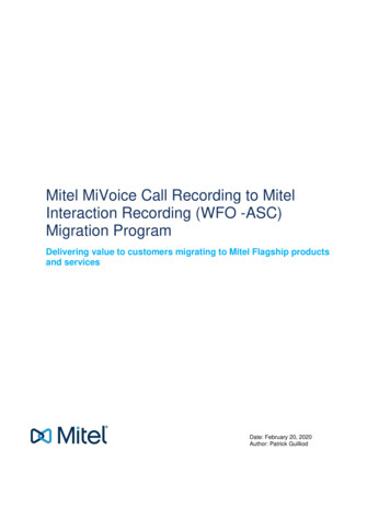
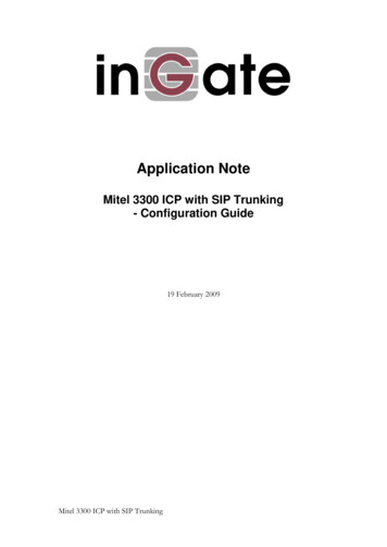
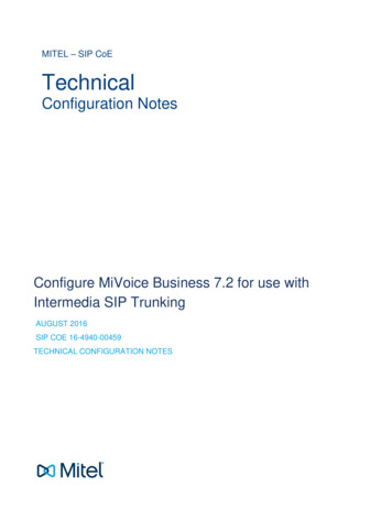
CHAPTER 3LINE AND REGISTER SIGNALINGBASIC SIGNALINGLine and Register SignalingCAS is traditionally divided into line signaling and register signaling. There is no need for this division inCCS.Line signals are simple information in contrast to register signals. Line signals are needed during thewhole call while register signals are used only during the call set up.By dividing the signaling equipment into register and line signaling equipment, and using the morecomplex register equipment only while the address information is transmitted, one register equipmentmay be used to serve many lines.Notice the difference between this division based on what information the signals transfer, and divisionsbased on the different principles of signaling (for example, CAS, CCS see above) or techniques used totransfer the signals (for example, impulsing, tone code).Line signalingSeizure, answer and clearing are examples of line signals.Examples of techniques used for line signaling are DC signaling (Direct Current) and digital signaling (intime slot 16 on a PCM link).Register signalingThis is mainly used for conveying the called number.Examples of techniques used for register signaling are impulsing (decadic pulsing) and tone code (forexample, DTMF, MFC).Example of SignalingIn the figure below is an example of signaling between exchanges using a CAS signaling system. Theexample shows a basic call from A to B where the B-party hangs up first.2/154 31-ANF 901 14 Uen J 2019-10-187
EXAMPLE OF SIGNALINGBASIC SIGNALINGCHAPTER 3Figure 3.1: Signaling for a basic call2/154 31-ANF 901 14 Uen J 2019-10-188
CHAPTER 4TOOLSPREREQUISITEPrerequisiteNetwork Services are administered with the LC commands.Tools--References--Execution - Routing, GeneralTo set up a route in the MX-ONE system, a selection of MML commands are necessary.A route is identified by the system by its route number which is a fictitious sequence number. The routeis given certain characteristics, some characteristics are used by the system (in command ROCAI) andothers are used by the interface between the system and the external line (in command RODAI).An external line is physically connected to the system either to the front of a TLU board or to the front ofthe Media Gateway. The H.323 and SIP trunk uses the ordinary LAN connection.An external line is logically connected to the system by associating a route to an equipment position (bycommand ROEQI ). At the same time the external line (equipment position) is given a sequence numberbased on to which LIM the line is connected. This sequence number is used for outgoing calls at the lineselection which can be done in different ways.A route can have external lines in several media gateways and in several LIMs (servers), providing distribution of the traffic load for the route. The method for selection of the lines can be configured (commandROCAI, parameter SEL).H.323 and SIP routes represent exceptions to the previous statements. First, these types of routes makeuse of an IP interface (RTP resource) board (MGU) instead of a TLU board, since it is the same interfaceas the IP extension. IP interface boards are connected directly to the data network.There is no association between physical equipment positions in the IP board and external lines. IP interface boards are capable of supporting more calls than equipment individuals, given that not all calls needboard media resources and if needed, those resources can be borrowed from another board. So, it ispossible to initiate more external lines than board positions. H.323 or SIP external lines are not attachedto an equipment position.2/154 31-ANF 901 14 Uen J 2019-10-189
CHAPTER 5TOOLSTools--2/154 31-ANF 901 14 Uen J 2019-10-1810
CHAPTER 6REFERENCESReferences--2/154 31-ANF 901 14 Uen J 2019-10-1811
CHAPTER 7ROUTING, GENERALEXECUTIONExecutionThe execution is described in the following sections.Routing, GeneralTo set up a route in the MX-ONE system, a selection of MML commands are necessary.A route is identified by the system by its route number which is a fictitious sequence number. The routeis given certain characteristics, some characteristics are used by the system (in command ROCAI) andothers are used by the interface between the system and the external line (in command RODAI).An external line is physically connected to the system either to the front of a TLU board or to the front ofthe Media Gateway. The H.323 and SIP trunk uses the ordinary LAN connection.An external line is logically connected to the system by associating a route to an equipment position (bycommand ROEQI ). At the same time the external line (equipment position) is given a sequence numberbased on to which LIM the line is connected. This sequence number is used for outgoing calls at the lineselection which can be done in different ways.A route can have external lines in several media gateways and in several LIMs (servers), providing distribution of the traffic load for the route. The method for selection of the lines can be configured (commandROCAI, parameter SEL).H.323 and SIP routes represent exceptions to the previous statements. First, these types of routes makeuse of an IP interface (RTP resource) board (MGU) instead of a TLU board, since it is the same interfaceas the IP extension. IP interface boards are connected directly to the data network.There is no association between physical equipment positions in the IP board and external lines. IP interface boards are capable of supporting more calls than equipment individuals, given that not all calls needboard media resources and if needed, those resources can be borrowed from another board. So, it ispossible to initiate more external lines than board positions. H.323 or SIP external lines are not attachedto an equipment position.2/154 31-ANF 901 14 Uen J 2019-10-1812
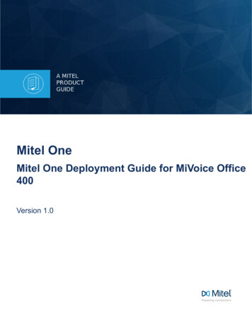
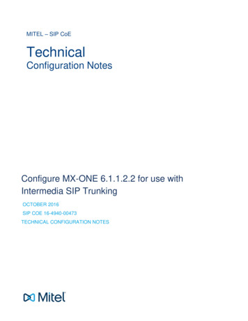
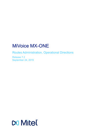
ROUTING, CCSS7EXECUTIONCHAPTER 7Routing, CCSS7Figure 7.1: Signaling description for CCSS7NOTE:LIM 1 and LIM 2 belong to the same PBX but are located at different places. Therefore they mayhave access to two different exchanges in the public network.In the figure above the route set RS1 is set up between Signaling Point Code (SPC) (A) and SPC(X).Signaling routes SR11 and SR22 belongs to RS1. A route set RS2 has to exist between SPC(A) andSPC(Y) but that is not shown in the figure.To set up a CCSS7 signaling link in the MX-ONE system, a selection of MML commands are necessary.MTSSIThe first thing to do is to initiate a link set with the command MTSSI. Parameters of special importanceare OPC, DPC and LNKSET.The parameters OPC and DPC are determined by the SPC values. The SPC values are provided whenrequesting a CCSS7 access from the public network.Parameter LNKSET states a specific signaling link set.MTSLISecondly, define the characteristics for the signaling links using command MTSLI . Parameters of specialimportance are LINK, LNKSET, PCMID and SLC.The parameter LNKSET states a specific signaling link set.The parameter PCMID states the PCM link identity of the board where the signaling link is situated. Thevalue is used to form the complete circuit identification code (CIC) of all external lines assigned to the2/154 31-ANF 901 14 Uen J 2019-10-1813
CHAPTER 7BASIC ROUTINGEXECUTIONboard. The parameter value specifies the most significant seven bits of the CIC. The remaining five bitsare determined by the corre sponding time slot used for the speech connection of the external lines.The parameter SLC states the code of a signaling link connecting two points in a common channelsignaling system No.7 network. The SLC is sent in message signal units (MSUs) to indicate the signalinglink, connecting the destination and originating points, to which the message is related.MTSTIThirdly, the signaling route set shall be initiated with command MTSTI. Parameters of special importanceare ROUSET, DPC and TEST.The parameter ROUSET states a signaling route set number.The parameter TEST states whether a signaling route test will be performed or not.MTSRINext to do is to initiate the signaling routes using command MTSRI . Parameters of special importance areSIGROU, ROUSET, LNKSET and PRIO.The parameter SIGROU states a signaling route number.The parameter PRIO states what priority the signal route has.MTSDCFinally the signaling links shall be activated. This can be done link by link or for the whole link set by usingcommand MTSDC. Parameters of special importance are LINK, LNKSET and DEACT.The parameter DEACT states whether the signaling link shall be deactivated (YES) or activated (NO). Ifthe parameter is omitted the value NO is assumed.Trunk LinesAfter initiating the link set, signaling links, route sets, and signaling routes, the trunk lines shall be initiatedfollowing the description in the next section. Variables that are of special importance for CCSS7 are: SERV D3: Type of route, shall be set to 0, trunk line. SERV D4: Call metering characteristics, shall be set to 1, call metering route. ADC D20-D21: Start Signaling Point (SSP). SIG D12 - Netservices, has to be set to 0, no net service facilities. CNTRL: Decides whether the trunk is controlled by its own (YES) or cooperating (NO) exchange. If theOriginating Code Point (OPC) is lower than the Destination Code Point (DPC) and the trunk individualis odd, the CNTRL parameter shall be set to YES.Basic RoutingBelow there is a description of the different commands that are necessary to initiate a route, in order toprovide it with its specific categories and characteristics.NOTE: For specific characteristics at route initiation and allowed categories for H.323 routes, see the operational directions for IP NETWORKING and also see the description for IP NETWORKING.ROCAIThe first thing to do is to initiate a route with the command ROCAI. Parameters of special importance areSEL, SERV and SIG.For the parameter SEL the following characteristics are of special interest:2/154 31-ANF 901 14 Uen J 2019-10-1814
CHAPTER 7BASIC ROUTINGEXECUTION Criteria for rerouting at DID traffic.If any rerouting criteria are set, command RODNI must be used to define the answering position to whichthe call should be rerouted.For manual incoming routes, the answering position is primarily defined by the commands OPCTS andOPCGS, see the operational directions for PBX OPERATOR TRAFFIC. Selection of a line at outgoing traffic.For instance, the line selection can be done in the way that the calls are evenly distributed among theexternal lines.For parameter SERV the following characteristics are of special interest: Whether the system is to handle the route as public (trunk line) or private (tie line).Used to provide correct ringing signal and display message at the called party.For parameter SIG the following characteristics are of special interest: Whether dial tone after seizure of the external line is to be generated in the own or received from theco-operating exchange at outgoing call. Whether the route has any clear signal.Used to check if the parties, that is, a party in the own exchange or an incoming or outgoing route, areallowed to be connected. If both parties lack the clear signal, the connection of the call is prohibited unlessthe call is extended and supervised by a PBX operator. PBX operator supervision of extended calls is alsostated in parameter SIG. When the switch should be through-connected Type of signaling system, that is, DPNSS, ISDN, H.323, MFC, decadic pulsing/DTMF, or CCSS7 Whether netservices are supported or not for H.323, DPNSS, or ISDN routesRODAISecond, define the characteristics used by the interface between the external line and the system withthe command RODAI . These characteristics depend on the type of signaling system and can be found inthe parameter description for the external line in question.NOTE: A value stating a specific characteristic for one type of route does not necessarily have the samemeaning for another route.There are three parameters for the purpose of stating characteristics. Parameter VARC is used for statingcommon characteristics, parameter VARI is used for stating characteristics specific for incoming traffic,and parameter VARO is used for stating characteristics specific for outgoing traffic.Typical characteristics are: type of signaling whether end of selection (EOS) should be sent whether B-answer should be sent whether B-answer should be received characteristics for different time supervisions specific differences within the concerned signaling system (protocol)ROEQIThird, the external line or lines should be logically connected to the route with the command ROEQI .number initiate, RODDI2/154 31-ANF 901 14 Uen J
words: Speech and signals travel together. CCS - Common Channel Signaling A method of signaling between two exchanges. Signals relating to a number of channels are transmitted over a single data link, in addressed messages. In other words: Speech and signals travel independently, both in time and media. CCSS7 - Common Channel Signaling System No. 7