Transcription
Chapter 12 421Horizontal Directional DrillingChapter 12Horizontal Directional DrillingIntroductionThe Horizontal Directional Drilling (HDD) Industry has experiencedso much growth in the past two decades that HDD has becomecommonplace as a method of installation. One source reportedthat the number of units in use increased by more than a hundredfold in the decade following 1984. This growth has been drivenby the benefits offered to utility owners (such as the eliminationof traffic disruption and minimal surface damage) and by theingenuity of contractors in developing this technology. To date,HDD pipe engineering has focused on installation techniques, andrightfully so. In many cases, the pipe experiences its maximumlifetime loads during the pullback operation.The purpose of this chapter is to acquaint the reader with some ofthe important considerations in selecting the proper PE pipe. Properselection of pipe involves consideration not only of installationdesign factors such as pullback force limits and collapse resistance,but also of the long-term performance of the pipe once installed inthe bore-hole. The information herein is not all-inclusive; there maybe parameters not discussed that will have significant bearing onthe proper engineering of an application and the pipe selection.For specific projects, the reader is advised to consult with a qualifiedengineer to evaluate the project and prepare a specificationincluding recommendations for design and installation and for pipeselection. The reader may find additional design and installationinformation in ASTM F1962, “Standard Guide for Use of MaxiHorizontal Directional Drilling for Placement of PE Pipe or ConduitUnder Obstacles, Including River Crossings,” and in the ASCEManual of Practice 108, “Pipeline Design for Installation byDirectional Drilling.”421-461.indd 4211/16/09 10:15:03 AM
422Chapter 12Horizontal Directional DrillingBackgroundSome of the earliest uses of large diameter PE pipe in directional drilling were forriver crossings. These are major engineering projects requiring thoughtful design,installation, and construction, while offering the owner the security of deep riverbed cover with minimum environmental damage or exposure, and no disruption ofriver traffic. PE pipe is suited for these installations because of its scratch toleranceand the fused joining system which gives a zero-leak-rate joint with design tensilecapacity equal to that of the pipe.To date, directional drillers have installed PE pipe for gas, water, and sewer mains;communication conduits; electrical conduits; and a variety of chemical lines.These projects involved not only river crossings but also highway crossings andright-of-ways through developed areas so as not to disturb streets, driveways, andbusiness entrances.PE Pipe for Horizontal Directional DrillingThis chapter gives information on the pipe selection and design process. It is notintended to be a primer on directional drilling. The reader seeking such informationcan refer to the references of this chapter. Suggested documents are the “MiniHorizontal Directional Drilling Manual” (1) and the “Horizontal DirectionalDrilling Good Practices Guidelines” (2) published by the North American Society forTrenchless Technology (NASTT).Horizontal Directional Drilling ProcessKnowledge of the directional drilling process by the reader is assumed, but somereview may be of value in establishing common terminology. Briefly, the HDDprocess begins with boring a small, horizontal hole (pilot hole) under the crossingobstacle (e.g. a highway) with a continuous string of steel drill rod. When the borehead and rod emerge on the opposite side of the crossing, a special cutter, called aback reamer, is attached and pulled back through the pilot hole. The reamer boresout the pilot hole so that the pipe can be pulled through. The pipe is usually pulledthrough from the side of the crossing opposite the drill rig.Pilot HolePilot hole reaming is the key to a successful directional drilling project. It is asimportant to an HDD pipeline as backfill placement is to an open-cut pipeline.Properly trained crews can make the difference between a successful and anunsuccessful drilling program for a utility. Several institutions provide operatortraining programs, one of which is University of Texas at Arlington Center forUnderground Infrastructure Research and Education (CUIRE). Drilling the pilot hole421-461.indd 4221/16/09 10:15:03 AM
Chapter 12 423Horizontal Directional Drillingestablishes the path of the drill rod (“drill-path”) and subsequently the location ofthe PE pipe. Typically, the bore-head is tracked electronically so as to guide the holeto a pre-designed configuration. One of the key considerations in the design of thedrill-path is creating as large a radius of curvature as possible within the limits ofthe right-of-way, thus minimizing curvature. Curvature induces bending stressesand increases the pullback load due to the capstan effect. The capstan effect is theincrease in frictional drag when pulling the pipe around a curve due to a componentof the pulling force acting normal to the curvature. Higher tensile stresses reducethe pipe’s collapse resistance. The drill-path normally has curvature along its verticalprofile. Curvature requirements are dependent on site geometry (crossing length,required depth to provide safe cover, staging site location, etc.) But, the degreeof curvature is limited by the bending radius of the drill rod and the pipe. Moreoften, the permitted bending radius of the drill rod controls the curvature and thussignificant bending stresses do not occur in the pipe. The designer should minimizethe number of curves and maximize their radii of curvature in the right-of-wayby carefully choosing the entry and exit points. The driller should also attempt tominimize extraneous curvature due to undulations (dog-legs) from frequent overcorrecting alignment or from differences in the soil strata or cobbles.Pilot Hole ReamingThe REAMING operation consists of using an appropriate tool to open the pilothole to a slightly larger diameter than the carrier pipeline. The percentage oversizedepends on many variables including soil types, soil stability, depth, drilling mud,borehole hydrostatic pressure, etc. Normal over-sizing may be from 1.2 to 1.5 timesthe diameter of the carrier pipe. While the over-sizing is necessary for insertion, itmeans that the inserted pipe will have to sustain vertical earth pressures withoutsignificant side support from the surrounding soil.Prior to pullback, a final reaming pass is normally made using the same sizedreamer as will be used when the pipe is pulled back (swab pass). The swab passcleans the borehole, removes remaining fine gravels or clay clumps and can compactthe borehole walls.Drilling MudUsually a “drilling mud” such as fluid bentonite clay is injected into the bore duringcutting and reaming to stabilize the hole and remove soil cuttings. Drilling mudcan be made from clay or polymers. The primary clay for drilling mud is sodiummontmorillonite (bentonite). Properly ground and refined bentonite is added tofresh water to produce a “mud.” The mud reduces drilling torque, and gives stabilityand support to the bored hole. The fluid must have sufficient gel strength to keepcuttings suspended for transport, to form a filter cake on the borehole wall that421-461.indd 4231/16/09 10:15:03 AM
424Chapter 12Horizontal Directional Drillingcontains the water within the drilling fluid, and to provide lubrication between thepipe and the borehole on pullback. Drilling fluids are designed to match the soiland cutter. They are monitored throughout the process to make sure the bore staysopen, pumps are not overworked, and fluid circulation throughout the borehole ismaintained. Loss of circulation could cause a locking up and possibly overstressingof the pipe during pullback.Drilling muds are thixotropic and thus thicken when left undisturbed after pullback.However, unless cementitious agents are added, the thickened mud is no stiffer thanvery soft clay. Drilling mud provides little to no soil side-support for the pipe.PullbackThe pullback operation involves pulling the entire pipeline length in one segment(usually) back through the drilling mud along the reamed-hole pathway. Proper pipehandling, cradling, bending minimization, surface inspection, and fusion weldingprocedures need to be followed. Axial tension force readings, constant insertionvelocity, mud flow circulation/exit rates, and footage length installed should berecorded. The pullback speed ranges usually between 1 to 2 feet per minute.Mini-Horizontal Directional DrillingThe Industry distinguishes between mini-HDD and conventional HDD, which issometimes referred to as maxi-HDD. Mini-HDD rigs can typically handle pipes upto 10” or 12” diameter and are used primarily for utility construction in urban areas,whereas HDD rigs are typically capable of handling pipes as large as 48”diamter.These machines have significantly larger pullback forces ranging up to severalhundred thousand pounds.General GuidelinesThe designer will achieve the most efficient design for an application by consultingwith an experienced contractor and a qualified engineer. Here are some generalconsiderations that may help particularly in regard to site location for PE pipes:1. Select the crossing route to keep it to the shortest reasonable distance.2. Find routes and sites where the pipeline can be constructed in one continuouslength; or at least in long multiple segments fused together during insertion.3. Although compound curves have been done, try to use as straight a drill path aspossible.4. Avoid entry and exit elevation differences in excess of 50 feet; both points shouldbe as close as possible to the same elevation.421-461.indd 4241/16/09 10:15:03 AM
Chapter 12 425Horizontal Directional Drilling5. Locate all buried structures and utilities within 10 feet of the drill-path for miniHDD applications and within 25 feet of the drill-path for maxi-HDD applications.Crossing lines are typically exposed for exact location.6. Observe and avoid above-ground structures, such as power lines, which mightlimit the height available for construction equipment.7. The HDD process takes very little working space versus other methods.However, actual site space varies somewhat depending upon the crossingdistance, pipe diameter, and soil type.8. Long crossings with large diameter pipe need bigger, more powerful equipmentand drill rig.9. As pipe diameter increases, large volumes of drilling fluids must be pumped,requiring more/larger pumps and mud-cleaning and storage equipment.10. Space requirements for maxi-HDD rigs can range from a 100 feet wide by 150 feetlong entry plot for a 1000 ft crossing up to 200 feet wide by 300 feet long area for acrossing of 3000 or more feet.11. On the pipe side of the crossing, sufficient temporary space should be rented toallow fusing and joining the PE carrier pipe in a continuous string beginningabout 75 feet beyond the exit point with a width of 35 to 50 feet, depending on thepipe diameter. Space requirements for coiled pipe are considerably less. Largerpipe sizes require larger and heavier construction equipment which needs moremaneuvering room (though use of PE minimizes this). The initial pipe side “exit”location should be about 50’ W x 100’ L for most crossings, up to 100’ W x 150’ Lfor equipment needed in large diameter crossings.12. Obtain “as-built” drawings based on the final course followed by the reamerand the installed pipeline. The gravity forces may have caused the reamer to goslightly deeper than the pilot hole, and the buoyant pipe may be resting on thecrown of the reamed hole. The as-built drawings are essential to know the exactpipeline location and to avoid future third party damage.SafetySafety is a primary consideration for every directionally drilled project. While thischapter does not cover safety, there are several manuals that discuss safety includingthe manufacturer’s Operator’s Manual for the drilling rig and the EquipmentManufacturer’s Institute (EMI) Safety Manual: Directional DrillingTracking Equipment. (3)421-461.indd 4251/16/09 10:15:03 AM
426Chapter 12Horizontal Directional DrillingGeotechnical InvestigationBefore any serious thought is given to the pipe design or installation, the designerwill normally conduct a comprehensive geotechnical study to identify soilformations at the potential bore sites. The purpose of the investigation is not onlyto determine if directional drilling is feasible, but to establish the most efficient wayto accomplish it. With this information the best crossing route can be determined,drilling tools and procedures selected, and the pipe designed. The extent of thegeotechnical investigation often depends on the pipe diameter, bore length andthe nature of the crossing. Refer to ASTM F1962, Guide for Use of Maxi-HorizontalDirectional Drilling for Placement of Polyethylene Pipe or Conduit Under Obstacles,Including River Crossings (4) and ASCE MOP 108, Pipeline Design for Installation byHorizontal Directional Drilling (5) for additional information.During the survey, the geotechnical consultant will identify a number of relevantitems including the following:a. Soil identification to locate rock, rock inclusions, gravelly soils, loose deposits,discontinuities and hardpan.b. Soil strength and stability characteristicsc. Groundwater(Supplemental geotechnical data may be obtained from existing records, e.g. recentnearby bridge constructions, other pipeline/cable crossings in the area.)For long crossings, borings are typically taken at 700 ft intervals. For short crossings(1000 ft or less), as few as three borings may suffice. The borings should be near thedrill-path to give accurate soil data, but sufficiently far from the borehole to avoidpressurized mud from following natural ground fissures and rupturing to theground surface through the soil-test bore hole. A rule-of -thumb is to take boringsat least 30 ft to either side of bore path. Although these are good general rules, thenumber, depth and location of boreholes is best determined by the geotechnicalengineer.Geotechnical Data For River CrossingsRiver crossings require additional information such as a study to identify riverbed, river bed depth, stability (lateral as well as scour), and river width. Typically,pipes are installed to a depth of at least 20 ft below the expected future riverbottom, considering scour. Soil borings for geotechnical investigation are generallyconducted to 40 ft below river bottom.421-461.indd 4261/16/09 10:15:04 AM
Chapter 12 427Horizontal Directional DrillingSummaryThe best conducted projects are handled by a team approach with the designengineer, bidding contractors and geotechnical engineer participating prior to thepreparation of contract documents. The geotechnical investigation is usually thefirst step in the boring project. Once the geotechnical investigation is completed, adetermination can be made whether HDD can be used. At that time, design of boththe PE pipe and the installation can begin. The preceding paragraphs representgeneral guidance and considerations for planning and designing an HDD PEpipeline project. These overall topics can be very detailed in nature. Individual HDDcontractors and consultant engineering firms should be contacted and utilized in theplanning and design stage. Common sense along with a rational in-depth analysisof all pertinent considerations should prevail. Care should be given in evaluatingand selecting an HDD contractor based upon successful projects, qualifications,experience and diligence. A team effort, strategic partnership and risk-sharing maybe indicated.Product Design: PE Pipe DR SelectionAfter completion of the geotechnical investigation and determination that HDDis feasible, the designer turns attention to selecting the proper pipe. The properpipe must satisfy all hydraulic requirements of the line including flow capacity,working pressure rating, and surge or vacuum capacity. These considerations haveto be met regardless of the method of installation. Design of the pipe for hydraulicconsiderations can be found in Chapter 6. For HDD applications, in addition tothe hydraulic requirements, the pipe must be able to withstand (1) pullback loadswhich include tensile pull forces, external hydrostatic pressure, and tensile bendingstresses, and (2) external service loads (post-installation soil, groundwater, andsurcharge loads occurring over the life of the pipeline). Often the load the pipe seesduring installation such as the combined pulling force and external pressure willbe the largest load experienced by the pipe during its life. The remainder of thisdocument will discuss the DR (Dimension Ratio) selection based on pullback andexternal service loads. (PE pipe is classified by DR. The DR is the “dimension ratio”and equals the pipe’s outer diameter divided by the minimum wall thickness.) Amore detailed explanation of the DR concept is provided in Chapter 5.While this chapter gives guidelines to assist the designer, the designer assumes allresponsibility for determining the appropriateness and applicability of the equationsand parameters given in this chapter for any specific application. Directional drillingis an evolving technology, and industry-wide design protocols are still developing.Proper design requires considerable professional judgment beyond the scope ofthis chapter. The designer is advised to consult ASTM F 1962, Guide for Use ofMaxi-Horizontal Directional Drilling for Placement of Polyethylene Pipe or Conduit421-461.indd 4271/16/09 10:15:04 AM
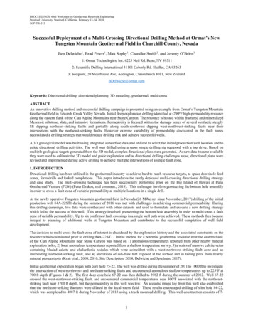
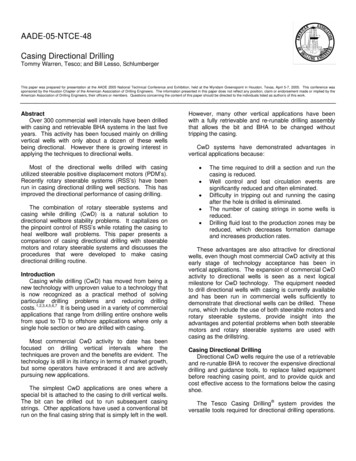
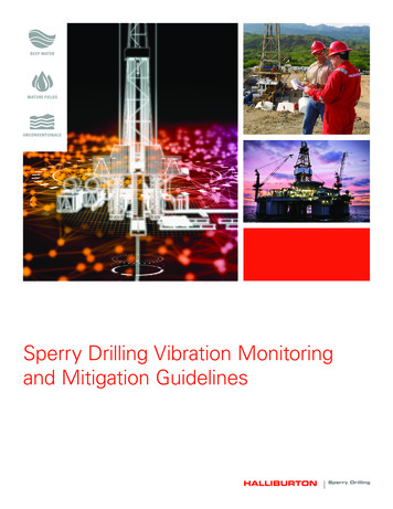
428 Chapter 12Horizontal Directional DrillingUnder Obstacles, Including River Crossings (4) when preparing an HDD design. Thismethodology is applied to designing municipal water pipe crossings as shown inPetroff (6).Normally, the designer starts the DR selection process by determining the DRrequirement for the internal pressure. The designer will then determine if this DRis sufficient to withstand earth, live, and groundwater service loads. If so, then theinstallation (pullback) forces are considered. Ultimately, the designer chooses aDR that will satisfy all three requirements: the pressure, the service loads, and thepullback load.Although there can be some pipe wall stresses generated by the combination ofinternal pressurization and wall bending or localized bearing, generally internalpressure and external service load stresses are treated as independent. This ispermissible primarily since PE is a ductile material and failure is usually driven bythe average stress rather than local maximums. There is a high safety factor appliedto the internal pressure, and internal pressurization significantly reduces stressesdue to external loads by re-rounding. (One exception to this is internal vacuum,which must be combined with the external pressure.)Figure 1 Borehole DeformationDesign Considerations for Net External LoadsThis and the following sections will discuss external buried loads that occur ondirectionally drilled pipes. One important factor in determining what load reaches thepipe is the condition of the borehole, i.e. whether it stays round and open or collapses.This will depend in great part on the type of ground, the boring techniques, and thepresence of slurry (drilling mud and cutting mixture). If the borehole does not deform(stays round) after drilling, earth loads are arched around the borehole and little soilpressure is transmitted to the pipe. The pressure acting on the pipe is the hydrostaticpressure due to the slurry or any groundwater present. The slurry itself may act tokeep the borehole open. If the borehole collapses or deforms substantially, earth421-461.indd 4281/16/09 10:15:04 AM
nes, consideration should be given to the time the line sitsfter construction. This may be several months. Most directionallycontain fluid will have a static head, which will remain in the lineChapter 12s head may be subtracted from the external pressureHorizontaldueDirectionalto Drillinger load. The designer should keep in mind that the external loadith time, for example, flooding.429pressurewill be applied to the pipe. The resulting pressure could exceed the slurryROUNDWATERPRESSUREpressure unless considerable tunnel arching occurs above the borehole. Where notunnel arching occurs, the applied external pressure is equal to the combined earth,reachwhenandthedeformsandinor,contactscanbe theusedpipeto establishtheboreholenetexternalpressureas it gs,unconsolidatedriver bedntsoil loadsoils,transmittedtoanticipatedthe pipewilldependontheextentoflittle archingis. ssurebetweentheinsideand outsideof thethegeostatic(sometimesbetweencalled the prismload).In consolidatedsoils,soil.archingEarthabove thed the relativestressstiffnessthepipeand theboreholeandcomplexity,the applied pressurewill likelyless thanthe geostaticot be uniform.Duemaytooccur,thisthereis benota simplestress, even after total collapse of the borehole crown onto the pipe. If the soil deposittingearth loadto height ofnetcover. Groundwaterloadingwill occurboreholecondition,pressureis definedbywith little oris a stiff clay,thecemented, orexternalpartially lithified,the boreholemay stay ureor,as it ise deforms ornonot;the onlyquestionis borehole):whetheror eformation.Incase,appliedpressure is likelyto be thejust theslurry head oralled,themaydifferentialbetweenthe whatinsideloadsand outsideof theandthusin fact pressurecontroldesign.Thus,reach thegroundwaterhead.the stabilityborehole.Pon additionPofI theto(1)the overt external pressures such as slurry head and groundwater,E PGW PSUR Infollowing equationscanbe used to establish the net external pressure or, as it isinternal vacuum in the pipe results in an increase in external pressure due to he boreholecondition,thenet pressureexternalpressureisdefinedby outside of therminingthe theatmosphericpressurefromthepipe. On ontheotherhand, aandpositivepipe.internal pressurein the pipeexternalpressure.engineerThe followingborehole)or mayEq.mediate2 (openborehole):edeformed/collapsedsoil, the designermaywishtoconsultathegeotechnicalcan be used to establish the net external pressure or, as it is sometimesdetermining equationsearth andgroundwater loads.called,thedifferentialpressure between the inside andexternaloutside of thepipe.Dependingontheboreholepressureis defined byPN PE PPNGW P MUDPSUR PIPI(1) condition, the net(2)on the boreholethe net externalis definedby eitherEq. 1Depending(deformed/collapsedborehole)or Eq.pressure2 (openborehole):e either- GroundwaterPressureOnlycondition,Eq. 1 (deformed/collapsed borehole) or Eq. 2 (open borehole): lledNetstableexternalpressure,PN PE roundPpsiPSUR deforms PI(1)if it(1)remainslittle after drilling. ForGW andExternalpressureduetoearthpressure,psiin competent rock will typically result in a stable borehole. Stable Groundwaterheightof riverpressurewater),PpressurePMUD (includingPI slurry the(2)occurin some(2)soilstheexertssufficienttoN whered and open hole. Since the deformations around the hole areWhere Surchargeandlivepsi are negligible. The external loadsurestransmittedto loads,thepipeP N Net externalpressure, psi Netexternalpressure,psithePPNinPMUD PI of due(2)nternalpressure,psi(negativeeventvacuum)peN consistsonlyof thehydrostaticpressureto the slurry orPE Externalpressuredue to earthpressure,psiP ncludingdrillingslurryor pressurepressureheightof river water),psigroundwaterr, ifE Hydrostaticpresent. PEquationgivesthethehydrostaticdue toGW Groundwater4 Groundwaterpressure(includingtheheightof river water),PGWif slurry canPSUR carrySurchargeshearand live loads,psiure,stress,psigrout. Standingwater should psibe added to the surfaceNetpsiexternalWhere:PI PInternalpressure,(negative in thepressure,event of vacuum)NpsiPMUDpressure ofpressuredrilling slurry or groundwaterifpressure,slurry can carry shearstress, psiPE Hydrostatic Externaldueto pressure,earthPSURSurchargeandliveloads,er,and surchargepressuresusedpsiin Eq.1 arediscussedin a psi(Earth, ground water, and surcharge pressures used in Eq. 1 are discussed in a following section of this(includingthe height of river water),PGW GroundwaterInternal chapter.)pressure,psi (negativepressurein the eventof vacuum)PI chapter.)thisgHWWpsiof drilling slurry or groundwaterPMUD Hydrostatic(3)(4)PGW g pressureMUD H B 2Pin Surchargeandlive loads,psiPMUDSURpressure, if slurrycancarrystress,psi2 shear144in 2(3)in the event of vacuum)psi (negativePI Internal144 2pressure,ftftWhere HydrostaticofdrillingslurryinorPfluidMUD pressureHydrostaticdue usedtopressuregroundsurfacewater,ndwater,andg surchargepressuresin Eq.and1 arediscusseda groundwaterW MUD Unit weight of slurry (drilling mud and cuttings), pcfif slurry can carry shear stress, psiitionof this chapter.)H B pressure, Elevation difference between lowest point in borehole and entry or exit pit, ft(144 is included for units conversion.)g MUD H BP (Earth,Unit weightofslurry(drillingmud2 and pressurescuttings), pcfMUDground water, and surchargeused in Eq. 1 are discussed in ain(3) intinboreholeand144of this12chapter.)2ftentry or exit pit, ft (144 is included for unitsconversion.)g MUDHBPMUDin 2(3)144will2 give carefulthe netexternal pressure, the designer421-461.indd 4291/16/09 10:15:04 AMft Unit weight of slurry (drilling mud and cuttings),pcfg
430Chapter 12Horizontal Directional DrillingWhen calculating the net external pressure, the designer will give carefulconsideration to enumerating all applied loads and their duration. In fact, mostpipelines go through operational cycles that include (1) unpressurized or beingdrained, (2) operating at working pressure, (3) flooding, (4) shutdowns, and (5)vacuum and peak pressure events. As each of these cases could result in a differentnet external pressure, the designer will consider all phases of the line’s life toestablish the design cases.In addition to determining the load, careful consideration must be given to theduration of each load. PE pipe is viscoelastic, that is, its effective properties dependon duration of loading. For instance, an HDD conduit resists constant groundwaterand soil pressure with its long-term apparant modulus stiffness. On the other hand,an HDD force-main may be subjected to a sudden vacuum resulting from waterhammer. When a vacuum occurs, the net external pressure equals the sum of theexternal pressure plus the vacuum. Since surge is instantaneous, it is resisted by thepipe’s short-term apparant modulus,, which can be four times higher than the longterm apparent modulus.For pressure lines, consideration should be given to the time the line sitsunpressurized after construction. This may be several months. Most directionallydrilled lines that contain fluid will have a static head, which will remain in the lineonce filled. This head may be subtracted from the external pressure due to earth/groundwater load. The designer should keep in mind that the external load also mayvary with time, for example, flooding.Earth and Groundwater PressureEarth loads can reach the pipe when the borehole deforms and contacts the pipe.The amount of soil load transmitted to the pipe will depend on the extent ofdeformation and the relative stiffness between the pipe and the soil. Earth loadingmay not be uniform. Due to this complexity, there is not a simple equation forrelating earth load to height of cover. Groundwater loading will occur whether thehole deforms or not; the only question is whether or not the slurry head is higher andthus may in fact control design. Thus, what loads reach the pipe will depend on thestability of the borehole.The designer may wish to consult a geotechnical engineer for assistance indetermining earth and groundwater loads, as the loads reaching the pipe dependon the nature of the soil.Stable Borehole - Groundwater Pressure OnlyA borehole is called stable if it remains round and deforms little after drilling. Forinstance, drilling in competent rock (rock that can be drilled without fracturing and421-461.indd 4301/16/09 10:15:04 AM
- Groundwater Pressure OnlyGroundwater Pressure OnlyChapter 12led stable if it remains round and deforms little after drilling.ForHorizontalDirectional Drillingdinstableif it remainsand resultdeformsafterdrilling. Forcompetentrock willroundtypicallyin allyresultinastableborehole.Stableccur in some soils where the slurry exerts sufficient pressure toin someslurryexerts sufficientto saroundpressurethe holeandhole. Sincedeformationsaroundhole areures opentransmittedto thethepipeare negligible.Thetheexternalloadcollapsing) will typically result in a stable borehole. Stable boreholes may occur oadpe consists onlyof thehydrostaticpressuredue tothe slurrysome soilswherethe slurry exertssufficient pressureto maintaina roundorand urry, if present. hole.Equationgives thehydrostaticpressuredueortoSince the 4deformationsaroundthe hole are small,soil pressurestransmittedf grout.present.StandingEquation4 negligible.gives waterthehydrostaticpressureto the pipesurfaceareThe externalload appliedtoaddedthe pipe dueconsistsonly ofshouldbeto tothegrout. Standingsurfacewatershouldadded iftopresent.the Equationthe hydrostaticpressuredue to theslurry or bethe groundwater,4314 gives the hyd
velocity, mud flow circulation/exit rates, and footage length installed should be recorded. The pullback speed ranges usually between 1 to 2 feet per minute. Mini-Horizontal Directional Drilling The Industry distinguishes between mini-HDD and conventional HDD, which is sometimes referred to as maxi-HDD. Mini-HDD rigs can typically handle pipes up