Transcription
Sperry Drilling Vibration Monitoringand Mitigation Guidelines
Table of Contents01 SPERRY DRILLING VIBRATION MONITORING AND MITIGATIONGUIDELINES502 DRILLSTRING MECHANICS AND VIBRATION MODES603 TYPES OF VIBRATION7»» Free or Natural Vibrations. . . . . . . . . . . . . . . . . . . . . . . . . . . . . . . . . . . . . . . . . . . . 7»» Forced Vibrations . . . . . . . . . . . . . . . . . . . . . . . . . . . . . . . . . . . . . . . . . . . . . . . . . . 7»» Self-Excited Vibrations . . . . . . . . . . . . . . . . . . . . . . . . . . . . . . . . . . . . . . . . . . . . . . 704 VIBRATION MECHANISMS8»» Stick-Slip / Low-Frequency Torsional Oscillation (LFTO) . . . . . . . . . . . . . . . . . . . . . 8»» Torsional Resonance / High-Frequency Torsional Oscillation (HFTO) . . . . . . . . . . . 9»» Bit Bounce. . . . . . . . . . . . . . . . . . . . . . . . . . . . . . . . . . . . . . . . . . . . . . . . . . . . . . . 9»» Bit Forward Whirl. . . . . . . . . . . . . . . . . . . . . . . . . . . . . . . . . . . . . . . . . . . . . . . . . . 9»» Bit Backward Whirl. . . . . . . . . . . . . . . . . . . . . . . . . . . . . . . . . . . . . . . . . . . . . . . . 10»» BHA Forward Whirl. . . . . . . . . . . . . . . . . . . . . . . . . . . . . . . . . . . . . . . . . . . . . . . . 10»» BHA Backward Whirl . . . . . . . . . . . . . . . . . . . . . . . . . . . . . . . . . . . . . . . . . . . . . . 10»» Lateral Shocks . . . . . . . . . . . . . . . . . . . . . . . . . . . . . . . . . . . . . . . . . . . . . . . . . . . 11The information contained in thisdocument does not serve as any formof warranty regarding the performanceof our tools or equipment. Thehighlighted data points and otherinformation provided are solelyintended to serve as threshold pointswhere and/or when environmentalparameters are known to causetool damage and/or acceleratedwear. This information should notbe relied upon, as various factorsmay affect the results dependingupon the circumstances. Halliburtonshall not be held liable for any lossor damage resulting from the useof the information contained herein,regardless of cause, including any actor omission of Halliburton. Halliburtonmakes no warranties of any kind,express or implied, whether fitness fora particular purpose, merchantabilityor otherwise, as to the accuracy ofany information.»» Parametric Resonance. . . . . . . . . . . . . . . . . . . . . . . . . . . . . . . . . . . . . . . . . . . . . 11»» BHA Harmonic Resonance. . . . . . . . . . . . . . . . . . . . . . . . . . . . . . . . . . . . . . . . . . 11»» Bit Chatter . . . . . . . . . . . . . . . . . . . . . . . . . . . . . . . . . . . . . . . . . . . . . . . . . . . . . . 12»» Stabilizer Contact Chatter. . . . . . . . . . . . . . . . . . . . . . . . . . . . . . . . . . . . . . . . . . . 12»» Modal Coupling . . . . . . . . . . . . . . . . . . . . . . . . . . . . . . . . . . . . . . . . . . . . . . . . . . 1205 FACTORS AFFECTING VIBRATION13»» Hole Angle. . . . . . . . . . . . . . . . . . . . . . . . . . . . . . . . . . . . . . . . . . . . . . . . . . . . . . 13»» Bit Type. . . . . . . . . . . . . . . . . . . . . . . . . . . . . . . . . . . . . . . . . . . . . . . . . . . . . . . . . 13»» Lithology. . . . . . . . . . . . . . . . . . . . . . . . . . . . . . . . . . . . . . . . . . . . . . . . . . . . . . . . 13»» Bit-Lithology Interaction. . . . . . . . . . . . . . . . . . . . . . . . . . . . . . . . . . . . . . . . . . . . 14»» Borehole Size / BHA Size. . . . . . . . . . . . . . . . . . . . . . . . . . . . . . . . . . . . . . . . . . . 14»» BHA Stabilization. . . . . . . . . . . . . . . . . . . . . . . . . . . . . . . . . . . . . . . . . . . . . . . . . 14»» Drilling Fluid Type. . . . . . . . . . . . . . . . . . . . . . . . . . . . . . . . . . . . . . . . . . . . . . . . . 14»» Rig Electrical System. . . . . . . . . . . . . . . . . . . . . . . . . . . . . . . . . . . . . . . . . . . . . . 14»» Rig Torque Limiters. . . . . . . . . . . . . . . . . . . . . . . . . . . . . . . . . . . . . . . . . . . . . . . . 14»» Auto-Drillers. . . . . . . . . . . . . . . . . . . . . . . . . . . . . . . . . . . . . . . . . . . . . . . . . . . . . 14»» Rig Heave. . . . . . . . . . . . . . . . . . . . . . . . . . . . . . . . . . . . . . . . . . . . . . . . . . . . . . . 14»» Backreaming with Excessively High RPM . . . . . . . . . . . . . . . . . . . . . . . . . . . . . . 14
Vibration Monitoring and Mitigation Guidelines06 DRILLSTRING INTEGRITY BEST PRACTICES15»» Pre-Well Planning. . . . . . . . . . . . . . . . . . . . . . . . . . . . . . . . . . . . . . . . . . . . . . . . . 15– Design Out Vibration»» During Drilling. . . . . . . . . . . . . . . . . . . . . . . . . . . . . . . . . . . . . . . . . . . . . . . . . . . . 16– Measure and React to Vibration»» Post-Drilling . . . . . . . . . . . . . . . . . . . . . . . . . . . . . . . . . . . . . . . . . . . . . . . . . . . . . 16– Analyze Memory Data and Capture Lessons Learned07 VIBRATION ALERT FLOWCHART1708 REAL-TIME DETECTION1809 REAL-TIME DISPLAYS20»» LOGIX Vibration Director . . . . . . . . . . . . . . . . . . . . . . . . . . . . . . . . . . . . . . . . . . 20»» Drilling Dynamics Advisor (DDA) . . . . . . . . . . . . . . . . . . . . . . . . . . . . . . . . . . . . . 20»» Real-Time Whirl Software . . . . . . . . . . . . . . . . . . . . . . . . . . . . . . . . . . . . . . . . . 20»» InSite Displays . . . . . . . . . . . . . . . . . . . . . . . . . . . . . . . . . . . . . . . . . . . . . . . . . . 2110 VIBRATION MODELING SOFTWARE22»» DrillingXpert Software – Max BHA Whirl Module (Geo-Pilot RSS) . . . . . . . . . 22»» DrillingXpert Software – Max BHA Whirl Module (iCruise System) . . . . . . . . . . 22»» DrillingXpert Software – WellPlan BHA Dynamics – Vibration Analysis. . . . . . 2211 VIBRATION SENSORS23»» Drillstring Dynamics Sensor (DDSr ) . . . . . . . . . . . . . . . . . . . . . . . . . . . . . . . . . 23»» GEO-PILOT TORSIONAL EFFICIENCY MONITOR (TEM). . . . . . . . . . . . . . . . . . 23»» DrilSaver III Vibration Monitoring System. . . . . . . . . . . . . . . . . . . . . . . . . . . . . 23»» Cerebro and Cerebro Force Sensors. . . . . . . . . . . . . . . . . . . . . . . . . . . . . . . . 24»» BaseStar / LithoStar / ResiStar Vibration . . . . . . . . . . . . . . . . . . . . . . . . . . 2412 VIBRATION OPERATING LIMITS25»» Vibration Operating Limit Tables. . . . . . . . . . . . . . . . . . . . . . . . . . . . . . . . . . . . . . 25
5Vibration Monitoring and Mitigation Guidelines01Sperry Drilling Vibration Monitoringand Mitigation GuidelinesSperry Drilling delivers engineered drilling solutionsand reservoir insight to maximize asset value.Vibration monitoring and mitigation delivers valueby reducing drilling trouble time, optimizing drillingpractices, and improving overall drilling performanceand well construction efficiency.During the planning phase, all bottomhole assemblies(BHAs) and bits are designed to eliminate theoccurrence of drilling vibration. During drilling, a suiteof tools, monitoring software, and expert advisoryservices are available to identify and mitigatevibration induced by the drilling environment. Thisis achieved through the pre-well and real-timeanalysis of critical data from a variety of downholeand surface sensors and specialized softwareapplications to model the BHA and monitor thedrilling process.The Drilling Engineering Solutions group providesBHA design experts during planning, along withApplied Drilling Technology (ADT ) optimizationservices during drilling, in order to optimizationservices during drilling to identify all modes andmechanisms of vibration, perform root causeanalysis, and improve designs to eliminate problems.All direction-drilling and logging-while-drilling (LWD)personnel are trained to recognize and react to thepresence of vibration when drilling to mitigate thenegative effects.This brochure provides an overview of the servicesthat are available, an explanation of all vibrationmodes and mechanisms, the factors affecting them, bestpractices and workflows, and the sensors and softwareutilized in the diagnosis and mitigation of vibration-relatedissues.Significant improvements in overall drilling performancecan be achieved by taking a proactive approach tothe prevention or reduction of destructive downholemechanical forces.Drillstring vibration and high shock loads are a majorcontributing factor to poor drilling performance, creatingboth visible and invisible non-productive time.The consequences of drilling vibration and high shockloads are:»» Inefficient drilling through wasted energy input,reducing rate of penetration (ROP) and increasingthe time to drill a section»» Bit/reamer damage, reducing the ROP and increasingbit/reamer costs»» Motor/rotary steerable damage causing unplanned trips»» Measurement-while-drilling (MWD) and LWD damageleading to lost data and unplanned trips»» Accelerated fatigue of all drillstring components,leading to collar and drillpipe washout or twist offand the potential for fishing trips and/or unplannedsidetracks around stuck assemblies»» Loss of wellbore strength and increased cavingthrough vibration damage to the borehole wall»» Interference with downhole tool telemetry, causinggaps in data»» Damage to rig equipment, causing increaseddowntime and cost
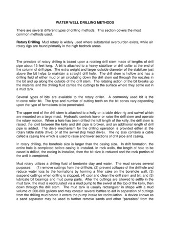
6Sperry Drilling02Drillstring Mechanics and Vibration ModesMechanically, the combined drillstring and BHAbehaves as a pipe, a beam, a column, and a shaft.It is a pipe to allow the flow of drilling fluidfrom surface to the bit and up the annulus. Themovement of the drilling fluid and pressuresgenerated creates deformation of the drillstringand associated stresses. The fluid system is usedto provide power to downhole tools (such as mudmotors or turbines), which imparts energy to the bitor the lower BHA.The drillstring behaves as a beam to facilitatedirectional drilling, as the BHA consists ofsegments of different stiffness that are deformedby the presence of stabilizers, bent housings,or rotary steerable point or push mechanismsto deflect the bit in the direction required. Thedrillstring will also conform to the wellbore, eitherfollowing the shape of the well exactly or straddlingsections of high dogleg, hole enlargements, orledges.In a vertical or near-vertical well, the BHA anddrillstring behave as a column that can becomeunstable and create buckling in either a sinusoidalor helical form. Stabilization is used to resist thebuckling in the BHA. As the hole angle is increased,the drillstring and BHA will contact the wellboreand become more stable and require a highercompressive force to create buckling.It behaves as a shaft, as rotational movement mustbe transmitted from the drive system to the bit,and torque must be transmitted to overcome thefrictional resistance of the drillstring against thewellbore in high-angle wells and the cutting actionof the bit, underreamers, or hole openers.The drillstring and BHA have six degrees of freedomwith three mutually orthogonal axes: X, Y, and Z.The convention is that X and Y are perpendicular tothe drillstring, with Z oriented parallel to the longaxis. X is oriented to measure lateral and radialaccelerations, and Y is oriented to measure lateraland tangential accelerations. The Z axis is orientedto measure axial vibration.The drillstring is free to move along each of theseaxes and to rotate around them. Rotation aroundthe Z axis describes the rotational speed of thedrillstring and responds to any twisting or torsionalvibration. Any rotational movement around theX and Y axes is constrained by the presence ofthe wellbore limiting movement as a function ofthe difference in the wellbore diameter and theoutside diameter of the drillstring component. Thismovement can be considered as flexing or bucklingof the drillstring.The three primary vibration modes used to identifythe vibration mechanisms are lateral, axial, andtorsional. Vibration mechanisms are classifiedaccording to which of these modes dominates thedynamic behavior when vibration occurs and thespecific frequency range of the dominant vibration.
7Vibration Monitoring and Mitigation Guidelines03Types of VibrationFree or Natural VibrationsSelf-Excited VibrationsFree vibrations are excited by a non-repetitive force(impulse) applied to a system, and the system isthen allowed to respond without further excitation.The vibration can occur at one or more of thesystem’s natural frequencies (i.e., the period at whichthe material, due to its structure and shape, wantsto vibrate in one of the modes). If no damage occursbecause of the original impulse, the vibration willdecay because of the dissipation of energy throughsystem damping.Self-excited vibrations are caused by a constantenergy source, which may be either external orinternal to the system. It is defined as the conversionof a non-oscillatory energy into vibration. There aresimilarities to forced resonance, in that the systemwill vibrate at a natural frequency. However, theimportant difference is that the source of excitationis constant in this case, not periodic. Therefore,although the energy source has a bearing on theamplitude of the vibration, it has no bearing on thefrequency at which the system vibrates.Forced VibrationsForced vibrations are caused by a periodic externalexcitation source, such as a mass imbalance of theBHA during rotation with the period of the excitationforce in such an imbalanced system governed by therotational speed.When such a force acts on an elastic solid that hasits own natural frequency, the interaction of thefrequencies produces extremely large vibrations,when the forcing frequency and the naturalfrequencies are the same. This interaction is termedforced resonance or more commonly resonance.If the forced vibration is at a different frequency tothe natural frequency of the string, the resultingvibration amplitude may either increase or decrease,depending on the relationship of the interaction withinput period causing either constructive or destructiveinterference.Motion is initiated in an elastic solid by an externalnon-linearity, such as friction, causing displacementfrom its equilibrium. The constant energy sourcecontinues to input energy into the system, andthe material in the system stores the energy untilthe disturbing force is overcome and the systemmoves back toward equilibrium. However, as thesystem oscillates back toward equilibrium, the elasticproperties of the system cause an over-displacement,due to the natural tendency to oscillate, and thiscreates a situation where the non-linearity (friction)requires more storage of energy to overcome itduring the next oscillation – hence, the system isdisplaced further. This feedback due to the oscillationcontinues, effectively increasing the amplitude ofthe vibration.
8Sperry Drilling04Vibration MechanismsMechanismMode of VibrationExpectedFrequency RangeStick-Slip / Low-Frequency Torsional Oscillation (LFTO)Torsional0.1–5 HzTorsional Resonance / High-Frequency Torsional Oscillation (HFTO)Torsional10–800 HzBit BounceAxial1–10 HzBit Forward WhirlLateral- Torsional0.5–5 HzBit Backward WhirlLateral- Torsional10–50 HzBHA Forward WhirlLateral- Torsional0.5–5 HzBHA Backward WhirlLatera- Torsional5–20 HzLateral ShocksLateralIrregular ImpactsParametric ResonanceAxial- Lateral0.1–10 HzBHA Harmonic ResonanceLateral0.5–5 HzBit ChatterLateral- Torsional20–250 HzStabilizer Contact ChatterLateral10–50 HzModal CouplingLateral- Torsional and Axial0.1–20 HzStick-Slip / Low-Frequency TorsionalOscillation (LFTO)Description: A feedback mechanism between thedrillstring and the rotary drive system causes anon-uniform drillstring rotation and repeated full-stallevents. The torque required by the bit and drillstringto rotate exceeds the torque being supplied bythe rotary system, and the bit stalls. The drillstringbegins to twist, and the speed of the drillstring atsurface drops. This causes the rotary drive to applymore torque to maintain the set rotary speed – thusincreasing trapped torque, twist, and the storedpotential energy in the drillstring. When the appliedtorque is greater than the resistance, the bit anddrillstring break free and are accelerated by thetrapped torque, causing the RPM to accelerate
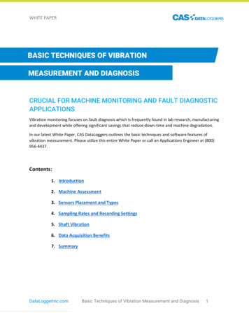
9Vibration Monitoring and Mitigation Guidelineshigher than the rotary system set point. Under extremeconditions, a reverse twist can be created in the drillstring,as the BHA accelerates faster than the surface stringRPM, creating a reverse twist and then a counter-rotationas the twist is released. After the increase in surfaceRPM, the rotary drive then reduces the applied torque toslow the drillstring down, and the torque drops below therequired threshold to maintain smooth rotation, and thenthe stick-and-slip cycle repeats. The frequency responseis a function of the length and stiffness of the drillstring,the mass of the BHA, and the rate at which the resistanceto rotation is overcome (Kyllingstad and Halsey, 1987).An instantaneous downhole RPM variation has beenmeasured between 2x to 15x the average surface RPM.The onset of this vibration mechanism, where the bit doesnot fully stall, can be described as low-frequency torsionaloscillation (LFTO). The frequency of the vibration is controlledby the mass of the BHA, and the length and stiffness ofthe drillstring. Weight-on-bit (WOB) fluctuations can also becreated by rig heave when offshore, with the period of heavebeing close to or at the the stick-slip frequency.Typical Environments: Affected environments can includehigh-angle or extended-reach wells, hard formations, or saltsections where salt creep is occurring, use of aggressivePDC bits with high WOB, high-tortuosity wellbores,wellbores with high friction factors caused by poor holequality or poor hole cleaning, and stiff BHA designs beingrun into high-dogleg sections.Consequences: Potential consequences can include largesurface torque fluctuations, causing damage to the rotarysystem; trapped torque, causing connection over-torqueand connection damage leading to drillstring twist-off;slip-phase reverse BHA rotation, causing connectionback- off; impact damage to PDC bits during the stickphase, with the potential for reverse rotation of PDC bitsand damage to PDC cutter diamond tables; damage tothe bit and stabilizer gauges, which can occur with therepeated rotational acceleration; and the stick-and-slipcycle can interfere with mud pulse telemetry by creatingpressure pulses at the bit if the stall frequency overlapsthe telemetry frequency.Torsional Resonance / High-Frequency TorsionalOscillation (HFTO)Description: This includes the excitation of a natural orharmonic torsional frequency of the drill collar (Warrenand Oster, 1998), and torsional resonance (or HFTO,as it has been more recently termed) occurs at naturalfrequencies of the BHA, typically greater than 50 Hz. Thevibration attenuates rapidly with distance from the bit andtends to be isolated only to the BHA – in many instances,below a motor where the elastomer serves to dampenHFTO propagation above the motor. HFTO matches exactlywith the higher torsional natural frequencies of thedrillstring (Jain et al., 2014).Typical Environment: These environments include hardrock, where PDC bits with high WOB and low RPM createa deep depth of cut.Consequences: The high-frequency torsional cycling candamage the elastomer in motor power sections, reducingtheir expected life. Additional consequences can includedamage to electronics, broken connectors and cables,and cracks appearing in tools and connections caused bycycling stresses.Bit BounceDescription: Bit bounce can be described as axial orlongitudinal motion of the drillstring generated by the bitinteraction with the formation, creating resonance in theaxial mode (Lubinski, 1950, and Dykstra et al.,1994).Typical Environments: These environments can includetricone bits with an unstable bottomhole pattern, creatingaxial resonance of the BHA; and vertical wells wherethere is no frictional damping between the drillstring andwellbore, especially in the absence of a shock absorber.Consequences: The impact loading will damage the drillbit cutting structure, bearings, and seals. The drillstringcan sustain damage from the axial shocks and lateralshocks induced by the string flexing. Hoisting equipmentmay be damaged in shallow wells. Additionally, downholeelectronics may be damaged from repeated shock.Bit Forward WhirlDescription: Bit forward whirl occurs when the bit hascut itself a hole larger than its own diameter (Brett etal., 1989). This allows the bit to precess around in thewellbore, instead of rotating around its natural center. Thehole enlargement can be relatively small for this to occur– 1/32 inch to 1/16 inch or 0.8 mm to 1.6 mm is sufficient.The frequency is 1x the RPM.Typical Environment: Bit forward whirl can be caused byexcessive side cutting on the bits or insufficient bit gaugepad support, or by softer or washed-out formations.
10Sperry DrillingConsequences: The primary consequence of bit forwardwhirl is the damage caused to PDC bit cutting structure.During the forward precession of the bit rotating in thehole, increased loading in directions different to theexpected vectors on the PDC cutters occurs – acceleratingthe bit wear, and reducing ROP and the length of the run.Whirling creates an over-gauge hole, thus reinforcing thetendency for the bit to whirl. Interbedded lithology ofdifferent compressive strengths and friability can lead tothe creation of ledges, as the weaker rock will be enlargedto a greater diameter than the stronger rock, which mayremain in gauge. This can lead to problems cleaning thehole and tripping the BHA.Bit Backward WhirlDescription: Bit backward whirl occurs when the bithas cut itself a hole larger than its own diameter that issufficient in size to allow the bit to pivot in the hole from apoint of contact on the bit blade for PDC bits of the conegauge on roller cone bits (Brett et al.,1989). This causesthe bit to precess around in the wellbore, insteadof rotating around its natural center. As the bit is constantlyrotating forward, the pivoting motion from the blade orcone contact causes the cutting structures to slide acrossthe face of the hole in a backward direction. The frequencyis the number of blades multiplied by the RPM, where “n”is a function of the hole enlargement and the bit outsidediameter (OD).Typical Environment: Bit backward whirl can be causedby excessive side cutting on the bits or insufficient bitgauge pad support, or by softer or washed-out formations.Consequences: The primary consequence of bit backwardwhirl is the damage caused to the PDC bit’s cuttingstructure. During the backward precession of the bitrotating in the hole, increased loading in directions differentto the expected vectors on the PDC cutters occurs– accelerating the bit wear, and reducing ROP and thelength of the run. Whirling creates an over-gauge hole, thusreinforcing the tendency for the bit to whirl and possiblyincreasing the hole size sufficiently to initiate BHA whirl.Interbedded lithology of different compressive strengthsand friability can lead to the creation of ledges, as theweaker rock will be enlarged to a greater diameter than thestronger rock, which may remain in gauge. This can lead toproblems cleaning the hole and tripping the BHA.BHA Forward WhirlDescription: BHA forward whirl is the eccentric rotationof the BHA about a point other than its geometric center,and is associated with the BHA rolling around the wellboreas it rotates. The eccentric rotation of whirling can becaused by a hole that has been enlarged, or by undergaugeBHA stabilizers or slick BHAs. The motion of the BHAin forward whirl has the center of rotation following acircular track around the wellbore. This can be initiated bya mass imbalance of the BHA or by friction between theBHA and the wellbore, causing the assembly to roll upthe side of the hole and drop down. This creates lateralshocks within the BHA, and, if the frequency of thelateral shocks matches a natural frequency of the BHA,then forced resonance will occur, significantly increasingthe magnitude of the lateral vibration and most likelytransitioning to BHA backward whirl (Besaisow andPayne, 1988; Vandiver et al.,1990; and Dareing, 1984).The frequency is 1x the RPM.Typical Environments: BHA forward whirl can occur in allhole sections with higher friction factors; zones with holeenlargements; vertical holes with poorly stabilized or slickBHAs; and BHAs operated with high RPMs and low WOB.Consequences: BHA forward whirl causes downholetool failure by generating high shock impacts andsustained vibration in the BHA. The repeated flexing ofthe drill collars at frequencies significantly higher thanthe rotational speed will increase the stress levels andsignificantly increase the number of cycles at higherstress, thus accelerating the fatigue rates of components.The potential high bending stresses can damage drill collarconnections, and the associated lateral shocks can causedownhole electronic failure. The surface torque level canalso increase, as more energy will be required to turn thevibrating BHA. The bit will exhibit wear on one side of thebit or gauge pad. The BHA and drillstring may show wearon one side of the stabilizers and collars, and this can alsobe evident in the drillpipe and tool joints.BHA Backward WhirlDescription: BHA backward whirl is the eccentricmovement of the BHA about a point other than itsgeometric center. The movement is created from highenergy shock impacts and is associated with the BHAbouncing off the wellbore in a direction different to therotational direction with each impact. It is common thatthe high energy shock impacts are created by forced
Vibration Monitoring and Mitigation Guidelinesresonance, but this is not always the case, as it can alsobe a product of excessively high RPM. BHA backwardwhirl can be initiated by straight-bladed stabilizersgearing off the wellbore in the same manner as with bitbackward whirl (Besaisow and Payne, 1988; Vandiveret al., 1990; and Dareing, 1984). The frequency is “n”multiplied by RPM, where “n” is a function of the holeenlargement and the collar or stabilizer OD.Typical Environments: This condition can be initiated bythe mass imbalance of the BHA or by the BHA resonatingat a critical rotary speed. BHA backward whirl can occur inall hole sections with higher friction factors, and in zoneswith hole enlargements. There can also be an increasedtendency for this to happen in vertical or overgauge holesections, or where the BHA is operating with high RPMand low WOB.Consequences: BHA backward whirl causes downholetool failure by generating high shock impacts andsustained vibration in the BHA. The repeated flexingof the drill collars at frequencies significantly higherthan the rotational speed will increase the stresslevels and significantly increase the number of cyclesat higher stress, thus accelerating the fatigue ratesof components. The potential high bending stressescan damage drill collar connections, potentially leadingto washouts or twist-offs, and the associated lateralshocks can cause downhole electronic failure. Thesurface torque level can also increase, as more energywill be required to turn the vibrating BHA. In weakerformations, damage from these shocks could result inhole enlargements.Lateral ShocksDescription: Chaotic behavior of the BHA and drillstringcan cause the release of energy built up in the drillstringthrough large lateral shock effects. Unlike BHA whirl,in which the motion settles to a steady state, the BHAmoves sideways and can briefly whirl forward orbackward randomly; this is a mechanical response towellbore condition, as opposed to resonance of theassembly or steady-state forward whirl (Mitchell andAllen, 1987).Typical Environments: Lateral shocks of the BHA canbe induced from too much energy in the drillstring andfrom excessively high RPM. These shocks can alsobe triggered by bit whirl or by rotating an unbalanceddrillstring. They can also occur with lateral movements11caused if the drillstring flexes during bit bounce. Theseshocks can occur in zones with hole enlargements, andthere can be an increased tendency
Sperry Drilling delivers engineered drilling solutions and reservoir insight to maximize asset value . Vibration monitoring and mitigation delivers value by reducing drilling trouble time, optimizing drilling practices, and improving overall drilling performance and well construction efficiency .