Transcription
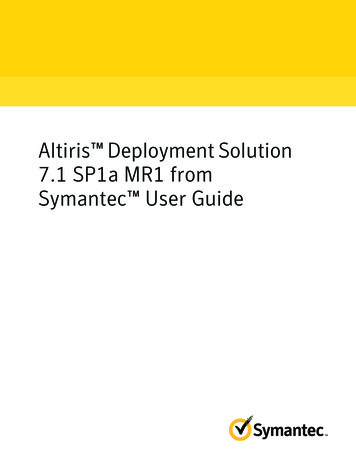
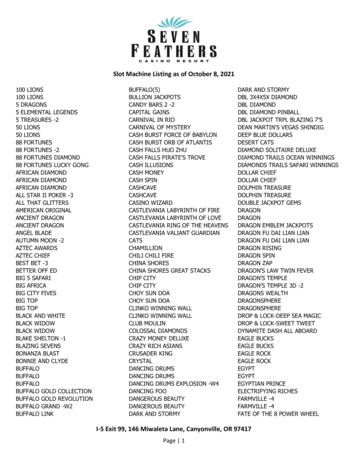
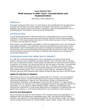
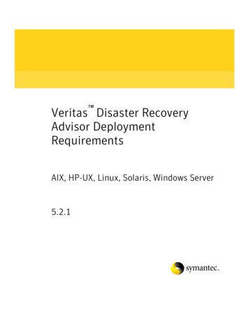
PROCEEDINGS, 43rd Workshop on Geothermal Reservoir EngineeringStanford University, Stanford, California, February 12-14, 2018SGP-TR-213Successful Deployment of a Multi-Crossing Directional Drilling Method at Ormat’s NewTungsten Mountain Geothermal Field in Churchill County, NevadaBen Delwiche1, Brad Peters1, Matt Sophy1, Chandler Smith2, and Jeremy O’Brien31: Ormat Technologies, Inc. 6225 Neil Rd. Reno, NV 895112: Scientific Drilling International 31101 Coberly Rd. Shafter, CA 932633: Seequent, 20 Moorhouse Ave, Addington, Christchurch 8011, New ZealandBDelwiche@ormat.comKeywords: Directional drilling, directional planning, 3D modeling, geothermal, multi-crossABSTRACTAn innovative drilling method and successful drilling campaign is presented using an example from Ormat’s Tungsten MountainGeothermal field in Edwards Creek Valley Nevada. Initial deep exploration drilling identified a 290oF high-permeability resourcealong the eastern flank of the Clan Alpine Mountains near Stone Canyon. The resource is hosted within fractured and mineralizedMesozoic siltstone, slate, and intrusive formations. Permeability is focused within the damage zones of several synthetic steeplySE dipping northeast-striking faults and partially along south-southwest dipping west-northwest-striking faults near theirintersections with the northeast-striking faults. However extreme variability of permeability discovered in the fault zonesnecessitated a drilling strategy that would reduce drilling risk and achieve successful wells.A 3D geological model was built using integrated subsurface data and utilized to select the initial production well location and toguide directional drilling activities. The well was drilled using a super single drilling rig equipped with a top drive. Based onmultiple geological targets generated from the 3D model, complex directional plans were generated. As new data became availablethey were used to calibrate the 3D model and guide exploration and as directional drilling challenges arose, directional plans wererevised and implemented during active drilling to achieve multiple intersections of a single fault zone.1. INTRODUCTIONDirectional drilling has been utilized in the geothermal industry to achieve hard to reach resource targets, to space downhole feedzones, for redrills and forked completions. This paper introduces the rarely deployed multi-crossing directional drilling strategyand case study. The multi-crossing technique has been successfully performed prior on the Big Island of Hawaii at PunaGeothermal Venture (PGV) (Peter Drakos, oral commun., 2018). This technique involves geosteering the bottom hole assemblyin order to cross a fault zone of variable permeability at multiple locations in a single drill.At the newly operative Tungsten Mountain geothermal field in Nevada (26 MWe net since November, 2017) drilling of the initialproduction well 84A-22ST1 during the summer of 2016 was met with challenges in achieving commercial permeability. Duringthis drilling campaign, live data were synthesized with other datasets and used to formulate and execute a new drilling strategywhich led to the success of this well. This strategy involved geosteering the bottom hole assembly in order to multi-cross a faultzone of variable permeability. Up to six confirmed fault crossings in a single well path were achieved. These methods then becameintegral to planning of additional wells at Tungsten Mountain and contributed to the successful completion of well fielddevelopment.The decision to multi-cross the fault zone of interest is elucidated by the exploration history and the associated constraints on theresource which culminated prior to drilling 84A-22ST1. Initial interest for a potential geothermal resource near the eastern flankof the Clan Alpine Mountains near Stone Canyon was based on 1) anomalous temperatures reported from prior nearby mineralexploration holes, 2) local anomalous temperatures reported from a shallow temperature survey, 3) a series of massive calcite veinscontaining bladed calcite and chalcedonic nodules which were coincident with a west-northwest-striking fault zone and anintersecting northeast-striking fault, and 4) alterations of ash-flow tuff exposed at the surface and in tailing piles from nearbymineral prospect pits (Kratt et al., 2008, 2010; Site Description, 2014; Delwiche and Spielman, 2017).Initial geothermal exploration began with core hole 75-22. The well was drilled during the summer of 2011 to 1000 ft to investigatethe intersection of west-northwest- and northeast-striking faults and encountered anomalous shallow temperatures up to 225oF at700 ft depth (Figures 1 & 2). The first deep core hole 67-22 was then drilled to 3982 ft during the summer of 2012. Well 67-22crossed the west-northwest-striking fault, and encountered commercial temperatures near 300oF associated with the northeaststriking fault near 3700 ft depth, but the permeability in this well was low. An acoustic image log from this well also establishedthat the northeast-striking fractures were dilated in the local stress field. These results encouraged drilling of slim hole 84-22,which was completed to 4087 ft during November of 2013 using a truck mounted drill rig. This well construction consists of 7-1
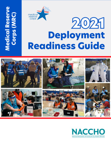
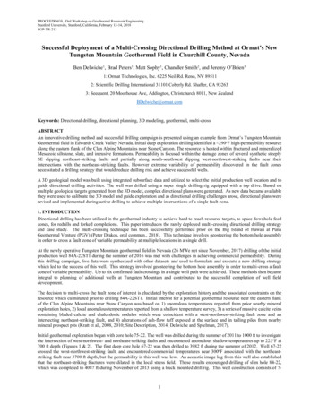
Delwiche et al.inch casing to 1936 ft and 6-1/8-inch hole to total depth completed with a 4-1/2-inch slotted liner. This well was drilled near therange front, encountered slate and siltstone basement rocks at only 1430 ft depth, and a total loss of circulation occurred where thenortheast-striking fault was intersected near 3950 ft depth (Figures 1 & 2). The rig test on this well indicated high permeabilitywith a producing fluid temperature of 285oF.An image log was collected in 84-22, but could not pass or image the fault zone at 3950 ft depth. However the location of the faultwas well constrained by a combination of surface data and directional surveys collected by a tri-axial magnetometer in 84-22 duringwellbore imaging. The fault was estimated to strike northeast and dip steeply 84o southeast (Figure 1). The encouragingtemperature and permeability in 84-22 justified twinning the target with a full-size well, 84A-22. Thus, prior to spudding 84A-22,the northeast-striking fault of interest was defined by 1) a small cuesta at the range front consisting of hydrothermally altered ashflow tuff and 2) the downhole intercept in 84-22. Based on near-isothermal temperatures in 84-22 below 2000 ft depth andslate/siltstone basement rock below 1430 ft depth it was inferred that the reservoir in the eastern part of the field is primarilycontained within the relatively homogeneous slate and siltstone basement rock formation within the fracture network of the faultzone (Figure 2). Thus commercial temperature and permeability could be encountered shallower than where it was encountered in84-22.During the initial drill of full-size well 84A-22, 13-3/8-inch casing was cemented to 2003 ft into the basement rock formation. Theproduction hole was drilled with 12-1/4-inch tricone bits to intercept the northeast-striking fault. The wellbore intersection withthe northeast-striking fault was inferred to occur at 2820 ft based on 1) a 40 barrel mudloss accompanied by 2) cuttings samplesthat contained traces of euhedral natrolite (hydrous sodium aluminum silicate, Na2Al2Si3O10 · 2H2O), euhedral quartz, andcataclasite consisting of angular slate fragments cemented in an amorphous silica matrix, and 3) a formation change from slate toa granodiorite intrusion. The granodiorite was not encountered in 84-22, and it appeared the intrusion was plugging the fault zone.Since only minor fluid losses occurred at the fault intercept a redrill was planned. Given the results of 84A-22, the low permeabilityin 67-22, and that the slim hole 84-22 feed zone had collapsed during a prior long-term test, there was general concern aboutachieving adequate permeability on a redrill. So this author worked with a directional planner from Scientific Drilling International(SDI) to understand the feasibility of multi-crossing the fault. Several fault crossings were planned with dogleg severities not toexceed 4o/100 ft to minimize torque and drag. SDI’s well planners used a torque and drag simulation to evaluate drilling issuessuch as stuck pipe. From a planning perspective, multi-crossing of the fault appeared feasible, but would require collaborationbetween drillers, geologist, and well planners to effectively mitigate challenges to achieve a successful well.2
Delwiche et al.Figure 1: Tungsten Mountain wellfield map with general geology. Units: Qa: Young alluvium; Qao: Old alluvium; Tt:late Oligocene ash-flow tuff sequence; Ta: mid-Oligocene andesite, dacite, and volcaniclastics; KJt: Mesozoic Tonalite;TRsl: Triassic slate and siltstone.3
Delwiche et al.Figure 2: Plot of static down hole temperatures and general lithology’s.2. METHODS2.1 ModelingPrior to drafting the directional plan for 84A-22ST1 the redrill targeting workflow utilized all available data to update the 3Dgeologic model. Data to import into the model may include directional surveys, drilling parameters, mudlog data, and any newlycollected downhole geophysical data (electrical or acoustic images, gamma, density porosity, neutron density, etc.). Directionalsurveys and wellhead coordinates must be checked for accuracy. Upon importing survey data, drill paths are calculated using themethod of spherical arc approximation also known as the minimum-curvature algorithm. This method is widely considered to bethe most accurate approximation of actual drill paths between survey points and is an industry standard (API, 1985; Use Manualfor Leapfrog Geothermal v. 3.5). Error ellipses associated with the well positions are generated by the well planner using softwaresuch as Compass 5000 and evaluated (e.g. Figure 7). This uncertainty effects both the position of the well being drilled and theposition of the fault targets if the modeled fault is tied to downhole data. The other drilling parameters and logged data are used todefine the distributions of rock-types, alterations, temperature, and faults.At least three widely separate locational constraints on a given fault are needed for adequate modeling precision and directionalplanning. The fault attitude in the model is of particular concern since its accuracy (location and orientation) has a large impact onthe depth at which the wellbore intercepts the fault. With a multi-crossing plan, there is also a risk of entirely missing the fault. Inthis case study, the fault plane is defined by a cuesta and scarp at the surface near the range front and by the two deep fault interceptsin 84-22 (3950 ft) and 84A-22 (2820 ft), respectively (Figure 2).4
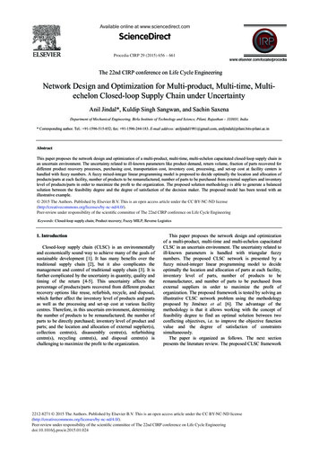
Delwiche et al.2.2 Directional PlanningDrafting a multi-crossing directional plan can be an iterative process between a geologist and directional planner. First, using the3D geologic model, a line is selected along the targeted fault zone at a location below the current total depth of the well. Theorientation of the line should be selected such that the required doglegs and total build angle of the drill path are minimized toachieve the line. If such data are available, the probable location of permeability should also be factored into selecting the faultline. Point targets are then selected at intervals along this fault line and a spreadsheet of target coordinates are generated andprovided to the directional planner to evaluate. The directional planner evaluates the current well position and construction anddetermines with the geologist an appropriate formation and depth for a kick-off point (KOP). Build angle rates are limited to 4o/100 ft, and the drill path is modeled to approach the fault plane subparallel. The fault also needs to be crossed such that the arcof the drilled path is oriented normal to the fault plane. This is necessary to minimize the length of the drilled path between faultintercepts. Radial distances between the arcs of the well path to the fault plane must be planned between each anticipated faultintercept (Figure 3). This radius is determined by looking at the error of position associated with both the fault plane and the surveypath. The thickness of the fault zone (if known) may also be factored into choosing a radius. The radius of the first two well patharcs may be larger than subsequent arcs because the position error of the fault is reduced once a crossing or two of the fault isachieved. For this initial multi-crossing directional plan, the first well path arc (between the first and second fault intercepts) radiuswas set to 10 ft in order ensure that the initial fault crossing was achieved (Figure 3). For the second well path arc (between thesecond and third fault intercepts) a radius of 3 ft was chosen (Figure 3). If the initial or second surveyed fault intercept etc. deviatesfrom what would be expected in the model, then the modeled fault may be edited, target coordinates regenerated, and a reviseddirectional plan drafted and implemented. The directional planner and geologist may need to work through several drafts and thenevaluate the plan with a torque and drag simulation before distribution and review by drilling engineers, directional drillers and rigcrews.5
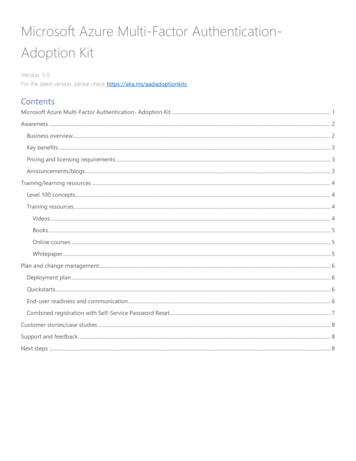
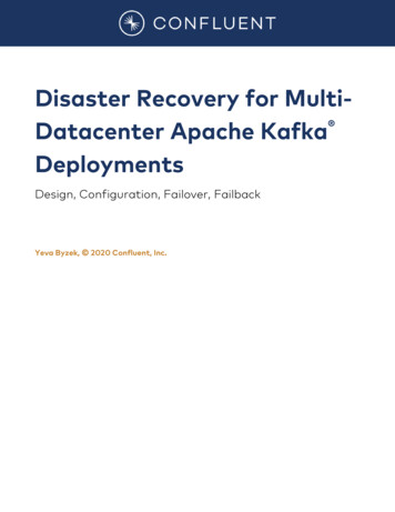
Delwiche et al.Figure 3: Initial multi-crossing plan (P4) including three fault intercepts.2.3 Choosing a Directional AssemblyDifferent possible configurations of the directional bottom hole assembly (BHA) may be utilized to accomplish a multi-crossingplan. A conventional conservative BHA may consist of a bit, mud motor with 1.5o bent sub, stabilizer with float, shock sub, nonmagnetic drill collar with directional sensor, non-magnetic pony collar, hang off sub, gap sub, non-magnetic pony collar, six drillcollars, jars, two more drill collars, and a cross-over below drill pipe (Figure 4a). The magnetic sensor utilizes magnetometers tomeasure wellbore position and can be subject to magnetic interference from the drill string, casing in offset wells, or minerals inthe formation. This BHA configuration allows for maximum reduction in potential magnetic interference of the drill string andallows for surveys to be collected 73 ft behind the bit. A high degree of confidence may be placed in the accuracy of your surveys,however, comparing surveys to predictions and reacting to deviations from anticipated yields is limited by the distance betweenthe bit and survey tool.Alternatively the BHA may be optimized such that directional surveys are taken closer to the bit than the conventionalconfiguration. Scientific Drilling International proposed a reconfigured BHA which consisted of a bit, mud motor with 1.5o bent6
Delwiche et al.sub and float, stabilizer with Gain Inclination and Gamma, a non-magnetic drill collar with directional sensor, hand off sub, gapsub, non-magnetic pony collar, shock sub, six drill collars, jars, two drill collars, and a cross-over below drill pipe (Figure 4b).This configuration may be subject to magnetic interference of the drill string although there is software such as Mag Comp whichcan compensate for the interference. Inclination measurements are taken with the Gain tool 33 ft from the bit and directionalsurveys are taken 51 ft behind the bit. The Gain tool utilizes gravity accelerometers to determine inclination and therefore is noteffected by magnetic fields. This configuration allows more proactive evaluation of trends, greater accuracy of predictions, andallows a faster reaction time if encountering unexpected results such as changing inclination or azimuth from what was anticipated.KF(A)(B)Figure 4: Schematics of directional bottom hole assemblies used. (A) conventional and (B) optimized.7
Delwiche et al.2.4 Directional DrillingWhile drilling directionally, surveys should be gathered every stand of drill pipe or about 42 ft and evaluated for accuracy. Slideintervals should be reamed to reduce drag and torque. The directional surveys including projections to bit should be regularlyupdated to the 3D geologic model and compared to the planned path and targets. The surveyed path needs to follow closely theplanned path, generally within a 5 ft radius. Frequent challenges may arise in following the plan and drilling risks includingwashouts in drill pipe, twist-offs and getting stuck are anticipated to be elevated while multi-crossing a fault. These anticipatedchallenges and risks associate with sliding through formation of a heterogeneous nature. Such formations are characterized by rockcompetency contrasts and variation of fabrics across the fault zone due to fracturing, shearing, and mineralization. If the surveypath diverges too far from the planned path, a new directional plan may be necessary to regain the fault in a manner which conservesdrilling depth while limiting dogleg severity and minimizes drag and torque (Chandler, 2011; Hearn et al., 2012).All drilling parameters should be monitored closely in order to gauge potential problems and to identify fault intercepts to comparewith predictions. At the depth where a fault is inferred to have been intercepted, the last directional survey could be up to 73 ftabove the zone of interest depending on the placement of the MWD in the BHA (Figure 4a). Therefore, once a fault interceptoccurs, a projection to bit is necessary to estimate the location of the fault for comparison to what was expected in the 3D model.However, given the influence of formation heterogeneity on the well path, the bit projections may be deviated from the actualsurvey once the MWD reaches the fault intercept depth. Although the bit projections may be deviated, for modeling purposes, thelocation of the fault intercept inferred from the bit projection generally will not change significantly from the fault intercept asconstrained by a directional survey. So, using the bit projection, the location of the fault intercept in the 3D model can initially becompared to the modeled fault for a cursory assessment and possible plan modification. Then once a directional survey at the depthof the fault intercept is acquired, the fault in the 3D model may be updated, new targets generated, and the directional plan and drillpath may be refined/adjusted.2.5 CompletionFor typical Ormat wells in Nevada, fluid losses are monitored during drilling and if significant losses occur and are sustained(generally 200 bph), the decision could be made to rig up air compressor and flow test equipment and drill directionally withaerated fluid in order to lift cuttings out of the hole and maintain open fractures. If a sustained total loss of circulation occurs thedirectional BHA would be replaced with a slick BHA with mud motor. This reduces lost-in-hole costs in the event of stuck pipewhile drilling in fractured formations. When drilling parameters indicate that adequate fracture permeability has been crossed, thehole is typically deepened beyond the last zone of interest for adequate rat hole. The hole is reamed to ensure gauge back flowedwith air to remove cuttings. A 9-5/8” slotted liner is then installed, and a production flow test performed.3. RESULTSThe redrill targets for Tungsten Mountain 84A-22ST1 were selected in order to intersect a fault at multiple intervals. Surface dataincluding a fault scarp and downhole parameters including two interpreted fault intercepts from two offset wells 84-22 and 84A22 provided the constraints for modeling of the fault plane. The fault of interest was modeled as a planar feature striking N44oEand dipping 83.1oSE using Leapfrog Geothermal software. Well position error was generated by the directional planner usingCompass 5000 software (Figure 7). Target coordinates were gathered along a line on the fault plane oriented N77oE and plunging75.6o and in a direction towards the 84-22 feed zone at 3950 ft depth and known permeability. A radius of 10 ft was chosen for thefirst well path arc (between fault intercepts 1 and 2) and a 3 ft radius was chosen for the second well path arc (between faultintercepts 2 and 3). Dogleg severity was planned as 4o/100 ft and three initial fault intercepts were planned (Figure 3).A conventional BHA was initially considered as the most cost effective and was deployed for the initial directional work (Figure4a). After pumping a balanced cement plug near 2400 ft, the well was sidetracked by time drilling to kick out of the original 84A22 hole. Achieving the first fault intercept required sliding and building a left-hand turn to 045o azimuth and inclination of 15ofrom vertical before turning back right (Figures 5a & 5b). Maximum dogleg severities between 4.3o to 5.68o/100 ft occurred from2652 to 2865 ft. The fault was encountered at 3060 ft in slate formation and was evidenced by a subtle 20 bph loss. No otherdrilling parameters indicated a possible fault except that the depth at which losses occurred was accurately predicted to the model.The hole was deepened maintaining the survey path close to the planned path. This required a right-hand turn up to 083o azimuthand building inclination up to 17o before turning back left and dropping inclination (Figures 5a & 5b). At 3420 to 3430 ft in slateformation a 75 bph loss occurred with a drilling break at 3419 ft. Cuttings samples in this interval contained a notable increase inmineralizations including predominately calcite fracture fill with lesser silica fracture fill and occurrences of euhedral comb quartzgrowths (Dong et al., 1995), abundant pyrite (FeS2) and arsenopyrite (FeAsS) as porphyroblasts and vein fill, and rare epidote(Ca2(Al,Fe)2(SiO4)3(OH)). Again, this intercept was very close to the predicted fault location, but this time the indicators of a faultwere much more obvious and provided confidence in the fault model. Maximum dogleg severities between 3.5o to 5.0o/100 ftoccurred from 3078 to 3291 ft. After this fault intercept, no revision of the 3D model was necessary and since the survey pathclosely maintained the planned path, a revised plan was also not necessary.The locations of the initial two fault crossings were accurate to the 3D model predictions and provided confidence in the deepertargets. The well was deepened towards the third fault target, which involved turning left and dropping angle (Figures 5a & 5b).The well was steered away from the plan in an attempt to stay in the fault zone and along the string of target coordinates. At 35958
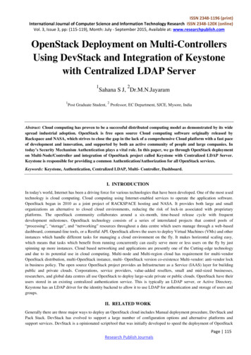
Delwiche et al.to 3635 ft the fault was intersected in slate formation, which was marked by a drilling break with a sudden drop in the hookload, a392 barrel mudloss (maximum rate of 330 bph), and abundant mineral and fracture indicators in the cuttings samples includingeuhedral natrolite and quartz, dogtooth calcite, amorphous silica fracture fill, and slickensided fracture material. Between 3466 and3594 ft depth, dogleg severities were 3o/100 ft. Within this fault zone, the lack of formation competency caused the BHA to dropbelow the fault until the formation was hard enough for the bit to build angle on slides. Mudlosses below the zone tapered to 80bph so the well was deepened to achieve greater fracture permeability.The initial three fault intercepts agreed well with the modeled fault, however additional permeability was required so a reviseddirectional plan was drafted to add additional fault intercepts. The drilling team deployed the optimized BHA in order to improvesurvey predictions and react more rapidly (Figure 4b). After a bit trip and installing the new BHA, the well was deepened from3702 ft and the BHA steered towards the right while building inclination. The fault was encountered a fourth time in slate basementrocks from 3725 to 3770 ft (Figures 5a & 5b). The fault intersection was accompanied by cuttings samples that consisted ofsecondary silica and calcite, cataclasite, and slickensided material. There were no additional mudlosses or drilling breaks associatedwith this fourth intercept. Upon exiting this fault zone, a dogleg of 7.48o/100 ft was incurred at 3740 ft, which resulted in deflectionof the well path away from the fault zone and an increase in the depth until the next anticipated fault crossing (Figures 5a & 5b).The plan was adjusted to accommodate the survey path and the BHA was steered towards the left and inclination reduced. TheMWD surveys indicated that inclination and turn were not changing rapidly enough to regain the fault (Figures 5a & 5b). The faultwas intended to be crossed near the 84-22 feed zone between 3950 to 4000 ft depth, but the lack of angle resulted in pushing theanticipated fault intercept deeper. The difficulty in achieving the build angle was attributed to relatively harder mineralizedformation towards the direction of the fault zone. The path diverged from the plan so a new plan was drafted. Longer slides wereattempted in order to cut towards the fault and resulted in doglegs 5.6 to 6.1o/100 ft between 3976 to 4062 ft. The fault was crossedagain near 4072-4130 ft depth. Again, no additional mudlosses were measured although the usual mineral and fracture indicatorswere noted. Upon deepening the well, a drilling break/fracture was encountered at 4352 to 4362 ft where an additional 80 bph ofmudlosses occurred. This did not correlate well to the modeled NE striking fault. The FMI log gathered later from 84A-22ST1indicated fractures near this depth strike northwest and dip moderately northeast.The well path was again turned towards the right and inclination increased in order to achieve a final sixth fault crossing. Additionalmudlosses began again at 4366 ft in slate formation accompanied by increased silica, common arsenopyrite and rare epidote in thesamples. This was presumed to be the sixth intercept of the fault. However, apparent from the wellbore imagery, the fault appearsto be at 4440 ft depth and is defined by a large open fracture (Figure 6). Losses incurred at 4362 and 4366 ft likely relate to partiallyopen fractures which connect in close proximity to the northeast-striking fault zone.Although a total loss of mud circulation was not encountered while drilling, numerous fault crossings were inferred based ondrilling data and alteration minerals in well cuttings. Since further drilling could lend to additional drilling risks, the well wascompleted to 4500 ft, reamed, back flowed with air assist to clean out, and completed with a 9-5/8” slotted liner to 4470 ft.A production test was conducted on June 2, 2016 to determine well productivity before moving the rig off the well. Open endeddrill pipe was set at 2003 ft and the well was lifted using an air compressor at 500 CFM. Fluid returns came to surface after thirtyminutes of air lift. After one hour and twenty-five minutes of cleanout, produced fluid was diverted through an atmosphericseparator with James tube and weir box to determine enthalpy and total flow. Once the test was completed, the air was shut offand after ten minutes, the well was shut in to measure the pressure buildup response for one hour. The maximum flow temperatureof 274oF was seen between 3655 to 3875 ft during the test. The average flow rate with air calculated using the weir box was 1522gpm during the test. A difference of 5.9 psi of pressure drawdown between static and flowing was measured so a productivityindex of 260 gpm/psi was calculated indicating a very permeable well. Wellbore spinner logs indicated fluid entering the wellborefrom 3900 to 4100 ft and near 3600 ft. Two other production tests performed later also confirmed high permeability and the wellwas put into production in November, 2017.9
Delwiche et al.83.1 oN44oEo83.1 SE(B)(A)Figure 5: (A) Profile view of well paths looking N44oE. Well path color scheme: green is slate, red is fault zone, and white is nosample returns. (B) Map view of well paths including fault targets (yellow points).10
Delwiche et al.Figure 6: Formation Micro Image of fault zone at 4440 ft depth. An irregular partially open fracture strikes 43 , dips 75 SE, andhas an aperture of 4 to 5 inches.11
Delwiche et al.4. DISCUSSIONMulti-crossing a fault zone lends to additional drilling challenges and risks, but appropriate preparation and methods can mitigate potentialproblems. Thorough reaming of slides, doglegs, and tight spots helps reduce torque and drag. Heterogeneities across a fault zone indeedlend to challenges in following a directional drilling plan and can lend to incurring doglegs, deflections, or not building enough angle. Inrelatively hard formation the bit may be able to build angle during slides, but if drilling subparallel to hard formation in relatively softerformation with the goal of achieving the harder formation, deflection of the bit can result in not achieving the target. Adjusting slidelengths based sole on observed survey behavior or ‘drilling the trend’ may not be the best approach for following the plan. Rather choosingslide lengths which would hedge estimates as to what would best avoid or mitigate the most detrimental potential outcomes. Acquisitionof surveys as close as possible to the bit allows faster response to well bore deviations. In subsequent wells at Tungsten Mountain, theoptimized directional BHA was deemed worth the additional costs compared to the conventional directional BHA.Other technologies which monitor downhole parameters as continuous measurements such as resistivity, gamma, and neutron porositymay also be considered for deployment, but each come with their respective price tag and relative benefit in the particular geologicenvironment and achieving the goals. The price tag associated with rotary steerable systems is also significantly more than a pulse mudmotor system and may lend to expensive repairs if the tools are damaged due to harsh conditions (hard fractured formation and hightemperatures) or lost in the hole due to stuck pipe.Successful multi-crossing of a fault zone requires a
The well was drilled using a super single drilling rig equipped with a top drive. Based on multiple geological targets generated from the 3D model, complex directional plans were generated. As new data became available they were used to calibrate the 3D model and guide exploration and as directional drilling challenges arose, directional plans were