Transcription
Voice over IP FundamentalsCopyright InformationCopyright 2000 Cisco PressCisco Press logo is a trademark of Cisco Systems, Inc.Published by:Cisco Press201 West 103rd StreetIndianapolis, IN 46290 USAAll rights reserved. No part of this book may be reproduced or transmitted in any formor by any means, electronic or mechanical, including photocopying, recording, or byany information storage and retrieval system, without written permission from thepublisher, except for the inclusion of brief quotations in a review.Printed in the United States of America 3 4 5 6 7 8 9 0Library of Congress Cataloging-in-Publication Number: 99-61716Warning and DisclaimerThis book is designed to provide information about Voice over IP. Every effort hasbeen made to make this book as complete and as accurate as possible, but nowarranty or fitness is implied.The information is provided on an "as is" basis. The authors, Cisco Press, and CiscoSystems, Inc., shall have neither liability nor responsibility to any person or entity withrespect to any loss or damages arising from the information contained in this book orfrom the use of the discs or programs that may accompany it.The opinions expressed in this book belong to the authors and are not necessarilythose of Cisco Systems, Inc.Trademark AcknowledgmentsAll terms mentioned in this book that are known to be trademarks or service markshave been appropriately capitalized. Cisco Press or Cisco Systems, Inc., cannotattest to the accuracy of this information. Use of a term in this book should not beregarded as affecting the validity of any trademark or service mark.Cisco Systems has more than 200 offices in the following countries.Addresses, phone numbers, and fax numbers are listed on the CiscoConnection Online Web site at http://www.cisco.com/offices. ArgentinaAustralia2
AustriaBelgiumBrazilCanadaChileChinaColombiaCosta RicaCroatiaCzech RepublicDenmarkDubai, UAEFinlandFranceGermanyGreeceHong reaLuxembourgMalaysiaMexicoThe NetherlandsNew ZealandNorwayPeruPhilippinesPolandPortugalPuerto RicoRomaniaRussiaSaudi ArabiaSingaporeSlovakiaSloveniaSouth raineUnited KingdomUnited States3
VenezuelaDedicationsJonathan Davidson:Wife, Daughter, SonTo my beautiful wife Shelly for putting up with me during the nights and weekendsspent working on this book. A better wife, mother, and friend could not be asked for.To my daughter Megan, who will probably be learning data and voice networking inhigh school by the time she gets there. Also, my son Ethan, who will probably thinkthat video and audio conferencing is as common as videogames and VCRs were tomy generation.James Peters:To my son Justin, for his curiousity, friendship, and the bond that we share.To my son Zachary, who has taught me to laugh and to not take life so seriously.To my daughter Breanna, whose smile makes me realize how beautiful life is.Voice over IP FundamentalsFeedback InformationAcknowledgmentsIntroductionPurpose of This BookAudienceChapter OrganizationFeatures and Text ConventionsTimelinessThe Road Ahead I: PSTN1. Overview of the PSTN and Comparisons to Voice over IPThe Beginning of the PSTNUnderstanding PSTN BasicsPSTN Services and ApplicationsDrivers Behind the Convergence Between Voice and Data NetworkingPacket Telephony Network DriversNew PSTN Network Infrastructure ModelSummary2. Enterprise Telephony TodaySimilarities Between PSTN and ETDifferences Between PSTN and ETCommon ET DesignsSummary3. Basic Telephony Signaling4
Signaling OverviewE&M SignalingCASISDNQSIGDPNSSSummary4. Signaling System 7SS7 Network ArchitectureSS7 Protocol OverviewSS7 ExamplesList of SS7 SpecificationsSummary5. PSTN ServicesPlain Old Telephone ServiceIntegrated Services Digital NetworkBusiness ServicesService Provider ServicesSummaryII: Voice over IP Technology6. Voice over IP Benefits and ApplicationsKey Benefits of VoIPPacket Telephony Call CentersService Provider Calling-Card Case StudyValue-Added ServicesEnterprise Case Study: Acme CorporationSummary7. IP TutorialOSI Reference ModelInternet ProtocolData Link Layer AddressesIP AddressingRouting ProtocolsEIGRPIP Transport MechanismsSummaryReferences8. VoIP: An In-Depth AnalysisDelay/LatencyJitterPulse Code ModulationVoice CompressionEchoPacket LossVoice Activity DetectionDigital-to-Analog ConversionTandem EncodingTransport ProtocolsDial-Plan DesignEnd Office Switch Call-Flow Versus IP Phone CallSummaryReferences9. Quality of Service5
QoS Network ToolkitEdge FunctionsTraffic PolicingBackbone NetworksRules of Thumb for QoSCisco Labs' QoS TestingSummaryIII: IP Signaling Protocols10. H.323H.323 ElementsH.323 Protocol SuiteH.323 Call-FlowsSummary11. Session Initiation ProtocolSIP OverviewSIP MessagesBasic Operation of SIPSummary12. Gateway Control ProtocolsSimple Gateway Control ProtocolMedia Gateway Control ProtocolSummary13. Virtual Switch ControllerOverview of the Virtual SwitchOpen Packet TelephonyPacket Voice Network OverviewVSC Architecture and OperationsVSC ImplementationSummaryIV: Voice over IP Applied14. Voice over IP Configuration IssuesDial-Plan ConsiderationsFeature TransparencyCisco's Dial-Plan ImplementationSummary15. Voice over IP Applications and ServicesEnterprise Applications and BenefitsEnterprise VoIP Case Study: B.A.N.C. Financing InternationalService Provider Case Study: Prepaid Calling CardSummaryA. ISUP Messages/ Types FormatsFeedback InformationAt Cisco Press, our goal is to create in-depth technical books of the highest quality and value. Each book iscrafted with care and precision, undergoing rigorous development that involves the unique expertise ofmembers from the professional technical community.6
Reader feedback is a natural continuation of this process. If you have any comments regarding how we couldimprove the quality of this book, or otherwise alter it to better suit your needs, you can contact us through email at ciscopress@mcp.com. Please make sure to include the book title and ISBN in your message.We greatly appreciate your assistance.AcknowledgmentsJonathan Davidson:To Brian Gracely, Gene Arantowicz, and James Peters—for without their help, this book would not be what it istoday.Many other people helped in answering questions and providing guidance as to the proper path both for thisbook and my knowledge of VoIP: Mark Monday, Cary Fitzgerald, Binh Ha, Jas Jain, Herb Wildfeur, Gavin Jin,Mark Rumer, Mike Knappe, Tony Gallagher, Art Howarth, Rommel Bajamundi, Vikas Butaney, AlistairWoodman, Sanjay Kalra, Stephen Liu, Jim Murphy, Nour Elouali, Massimo Lucchina.Thanks to you all for your help and assistance.A special thanks to Art Howarth, Mark Monday, and Alistair Woodman for their always available professionaladvice and willingness to help.Also, a thank you to Cisco Systems for allowing individuals to pursue limitless knowledge and personal growthopportunities.And a thank you goes to the following people at Cisco Press:Alicia Buckley—For getting the project going and for her help and persuasion for keeping us "on the bike!"Kezia Endsley—This book truly would not be what it is today without all of the time, effort, and blood put intothis book on Kezia's part.Kathy Trace, Sheri Replin, and Lynette Quinn.James Peters:To Andrew Adamian, Mark Bakies, Jonathan Davidson, Cary Fitzgerald, Douglas Frosst, and CharlieGiancarlo, for which, without their guidance and support, this book would not be possible.To Kathy Trace, for taking the time and having the patience to help me become a better writer.I would also like to thank my family, Connie, Justin, Zachary, and Breanna, for putting up with the years of longhours and travel I spent learning and working in the Internet community.Finally, I thank Cisco Systems for providing an environment where employees are able to contribute andaccomplish tasks equal to their passion and interests.IntroductionMany of my friends rant about the simplicity and elegance of the Apple Macintosh computer. But, as with manytechnologies, the simpler the user's experience is, the more complex the underlying infrastructure must be.This is true of the telephone network.Currently more than 4,000 telephony service providers—inter-exchange carriers (IXCs), Competitive LocalExchange Carriers (CLECs), and so on—exist in the United States alone. Global deregulation of telephonemarkets is forcing government-owned incumbent telephone carriers to begin competing with new, often7
innovative carriers. These new carriers frequently use new infrastructures so that they can compete at a lowerprice point than the incumbent carriers. They also are using these new infrastructures to deploy newapplications to their customers faster than they can on legacy equipment.Many of these new carriers use Voice over IP (VoIP) to lower their cost of operations and give them theflexibility they need to enter the global marketplace.A key part of this flexibility is the ubiquity of the Internet Protocol (IP). Because of the prevalence of theInternet, and because IP is the de facto protocol connecting almost all devices, application developers can useIP to write an application only once for use in many different network types. This makes VoIP a powerfulservice platform for next-generation applications.Purpose of This BookWhat is VoIP and in what ways does it apply to you? VoIP provides the capability to break up your voice intosmall pieces (known as samples) and place them in an IP packet. Voice and data networking are complextechnologies. This book explains how telephony infrastructure is built and works today, major conceptsconcerning voice and data networking, transmission of voice over data, and IP signaling protocols used tointerwork with current telephony systems. It also answers the following key questions: What is IP?How is voice signaled in telephone networks today?What are the various IP signaling protocols, and which one is best for which types of networks?What is quality of service (QoS), and how does one ensure good voice quality in a network?In addition to covering these concepts, this book also explains the basics of VoIP so that a networkadministrator, software engineer, or someone simply interested in the technology has the foundation ofinformation needed to understand VoIP networks.This book is meant to accomplish the following goals: Provide an introduction to the basics of enterprise and public telephony networkingIntroduce IP networking conceptsProvide a solid explanation of how voice is transported over IP networksCover the various caveats of converging voice and data networksProvide detailed reference information on various Public Switched Telephone Network (PSTN) and IPsignaling protocolsAlthough this book contains plenty of technical information and suggestions for ways you can build a VoIPnetwork, it is not a design and implementation guide in that it doesn't really give you comparisons betweenactual voice gateways throughout the industry.AudienceEven though this book is written for anyone seeking to understand how to use IP to transport voice, its targetaudience comprises voice and networking experts. In the past, voice and data gurus did not have to knoweach other's jobs. In this world of time-division multiplexing (TDM) and packet convergence, however, it isimportant to understand how these technologies work. This book explains the details so that voice experts canbegin to understand data networking, and vice versa.This writing style generates yet another audience: Those who have limited data and voice networkingknowledge but are technically savvy will be able to understand the basics of both voice and data networkingalong with how the two converge.Despite its discussions of voice and data networking, this book is really about VoIP, and the protocols thataffect VoIP are explained in great detail. This makes this book a reference guide for those designing, building,deploying, or even writing software for VoIP networks.8
Readers familiar with IP networking might want to skip Chapter 7, "IP Tutorial." Similarly, voice-networkingexperts might want to skip Chapter 3, "Basic Telephony Signaling."Chapter OrganizationChapter 1, "Overview of the PSTN and Comparisons to Voice over IP," contrasts the similarities anddifferences between traditional TDM networks and networks running packetized voice.Chapter 2, "Enterprise Telephony Today," Chapter 3, "Basic Telephony Signaling," Chapter 4,"Signaling System 7," and Chapter 5,"PSTN Services," cover enterprise telephony, the basics of PSTNsignaling, Signaling System 7 (SS7), and other PSTN services. These chapters provide the backgroundinformation needed by data networking professionals who are just stepping into the voice realm. They also actas a good primer for those in specific voice areas that want to brush up on various other voice-networkingprotocols.Chapter 6, "Voice over IP Benefits and Applications," contrasts and compares in detail how packetvoice can run the same applications as the current telephony system but in a more cost-effective and scalablemanner.Chapter 7 is an introduction into the world of IP. Basic subnetting and the Open Systems Interconnection(OSI) reference model are covered, and comparisons between Transmission Control Protocol (TCP) and UserDatagram Protocol (UDP) are provided.Chapter 8, "VoIP: An In-Depth Analysis," and Chapter 9, "Quality of Service," go into great detail onVoIP and how all the functional components fit together to form a solution. They include discussions of jitter,latency, packet loss, codecs, QoS tools, mean opinion scores (MOSes), and the caveats to consider whenimplementing packet voice networks.Chapter 10, "H.323," Chapter 11, "Session Initiation Protocol," Chapter 12, "Gateway ControlProtocols," and Chapter 13, "Virtual Switch Controller," cover the various signaling protocols and howthey are wrapped together using Cisco's Virtual Switch Controller (VSC). These chapters enable implementersto understand how all the various VoIP components set up calls, tear down calls, and offer services.Chapter 14, "Voice over IP Configuration Issues," and Chapter 15, "Voice over IP Applicationsand Services," cover the functional components of using Cisco gateways to deploy a VoIP network. Thesechapters include configuration details and sample case studies.Features and Text ConventionsText design and content features used in this book are intended to make the complexities of VoIP clearer andmore accessible.Key terms are italicized the first time they are used and defined. In addition, key terms are spelled out andfollowed with their acronym in parentheses, where applicable. Cisco configuration commands appear in boldin regular text and monospace in listings.Note boxes point out areas of special concern or interest that might not fit precisely into the discussion at handbut are worth considering. Sometimes, these boxes contain extraneous information in the form of tips, andsometimes they appear in the form of warnings to help you avoid certain pitfalls.Chapter summaries provide a chance for readers to review and reflect upon the information discussed in eachchapter. A reader might also use these summaries to determine whether a particular chapter is appropriate tohim or her.References to further information, including many Requests For Comments (RFCs), are included at the end ofmany chapters. Although not all the references are cited directly in each chapter, all were useful to us as weprepared this book.9
TimelinessAs of the writing of this book, many new protocols concerning VoIP were still being designed and worked outby the standards bodies. Also, legal aspects of VoIP constantly arise in different parts of the world. Therefore,this book is meant as a guide, in that it provides necessary foundational information. The next step is to readnew signaling drafts from the Internet Engineering Task Force (IETF;http://www.ietf.org/) and theInternational Telecommunication Union (ITU; http://www.itu.int/). The International TelecommunicationUnion Telecommunication Standardization Sector (ITU-T) documents require a login password.The Road Ahead VoIP is changing the way telecommunications is being deployed globally. This change is synonymous withhow the Internet changed our lives to date. VoIP technology is a big step toward a world where informationand communication are the most important tools for success. We hope you enjoy reading this book as muchas we enjoyed writing it.Part I: PSTNChapter 1 Overview of the PSTN and Comparisons to Voice over IPChapter 2 Enterprise Telephony TodayChapter 3 Basic Telephony SignalingChapter 4 Signaling System 7Chapter 5 PSTN Services10
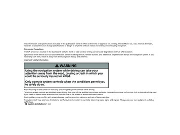
Chapter 1. Overview of the PSTN and Comparisons toVoice over IPThe Public Switched Telephone Network (PSTN) has been evolving ever since Alexander Graham Bell madethe first voice transmission over wire in 1876. But, before explaining the present state of the PSTN and what'sin store for the future, it is important that you understand PSTN history and it's basics. As such, this chapterdiscusses the beginnings of the PSTN and explains why the PSTN exists in its current state.This chapter also covers PSTN basics, components, and services to give you a good introduction to how thePSTN operates today. Finally, it discusses where the PSTN could be improved and ways in which it and othervoice networks are evolving to the point at which they combine data, video, and voice.The Beginning of the PSTNThe first voice transmission, sent by Alexander Graham Bell, was accomplished in 1876 through what is calleda ring-down circuit. A ring-down circuit means that there was no dialing of numbers, Instead, a physical wireconnected two devices. Basically, one person picked up the phone and another person was on the other end(no ringing was involved).Over time, this simple design evolved from a one-way voice transmission, by which only one user could speak,to a bi-directional voice transmission, whereby both users could speak. Moving the voices across the wirerequired a carbon microphone, a battery, an electromagnet, and an iron diaphragm.It also required a physical cable between each location that the user wanted to call. The concept of dialing anumber to reach a destination, however, did not exist at this time.To further illustrate the beginnings of the PSTN, see the basic four-telephone network shown in Figure 1-1.As you can see, a physical cable exists between each location.Figure 1-1. Basic Four-Phone NetworkPlace a physical cable between every household requiring access to a telephone, however, and you'll see thatsuch a setup is neither cost-effective nor feasible (see Figure 1-2). To determine how many lines you need to11
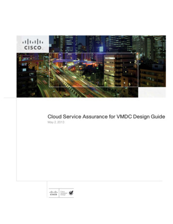
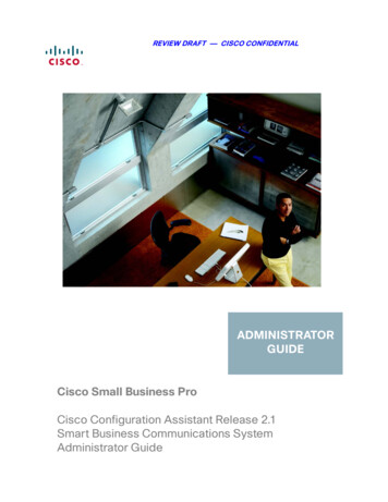
your house, think about everyone you call as a value of N and use the following equation: N (N–1)/2. Assuch, if you want to call 10 people, you need 45 pairs of lines running into your house.Figure 1-2. Physical Cable Between All Telephone UsersDue to the cost concerns and the impossibility of running a physical cable between everyone on Earth whowanted access to a telephone, another mechanism was developed that could map any phone to anotherphone. With this device, called a switch , the telephone users needed only one cable to the centralized switchoffice, instead of seven.At first, a telephone operator acted as the switch. This operator asked callers where they wanted to dial andthen manually connected the two voice paths. Figure 1-3 shows how the four-phone network example wouldlook today with a centralized operator to switch the calls.12
Figure 1-3. Centralized Operator: The Human SwitchNow, skip ahead 100 years or so—the human switch is replaced by electronic switches. At this point, you canlearn how the modern PSTN network is built.Understanding PSTN BasicsAlthough it is difficult to explain every component of the PSTN, this section explains the most important piecesthat make the PSTN work. The following sections discuss how your voice is transmitted across a digitalnetwork, basic circuit-switching concepts, and why your phone number is 10 digits long.Analog and Digital SignalingEverything you hear, including human speech, is in analog form. Until several decades ago, the telephonynetwork was based on an analog infrastructure as well.Although analog communication is ideal for human interaction, it is neither robust nor efficient at recoveringfrom line noise. (Line noise is normally caused by the introduction of static into a voice network.) In the earlytelephony network, analog transmission was passed through amplifiers to boost the signal. But, this practiceamplified not just the voice, but the line noise as well. This line noise resulted in an often unusable connection.Analog communication is a mix of time and amplitude. Figure 1-4, which takes a high-level view of an analogwaveform, shows what your voice looks like through an oscilloscope.13
Figure 1-4. Analog WaveformIf you were far away from the end office switch (which provides the physical cable to your home), an amplifiermight be required to boost the analog transmission (your voice). Analog signals that receive line noise candistort the analog waveform and cause garbled reception. This is more obvious to the listener if manyamplifiers are located between your home and the end office switch. Figure 1-5 shows that an amplifier doesnot clean the signal as it amplifies, but simply amplifies the distorted signal. This process of going throughseveral amplifiers with one voice signal is called accumulated noise .Figure 1-5. Analog Line DistortionIn digital networks, line noise is less of an issue because repeaters not only amplify the signal, but clean it toits original condition. This is possible with digital communication because such communication is based on 1sand 0s. So, as shown in Figure 1-6, the repeater (a digital amplifier) only has to decide whether to regeneratea 1 or a 0.14
Figure 1-6. Digital Line DistortionTherefore, when signals are repeated, a clean sound is maintained. When the benefits of this digitalrepresentation became evident, the telephony network migrated to pulse code modulation (PCM).Digital Voice SignalsPCM is the most common method of encoding an analog voice signal into a digital stream of 1s and 0s. Allsampling techniques use the Nyquist theorem , which basically states that if you sample at twice the highestfrequency on a voice line, you achieve good-quality voice transmission.The PCM process is as follows: Analog waveforms are put through a voice frequency filter to filter out anything greater than 4000 Hz.These frequencies are filtered to 4000 Hz to limit the amount of crosstalk in the voice network. Usingthe Nyquist theorem, you need to sample at 8000 samples per second to achieve good-quality voicetransmission.The filtered analog signal is then sampled at a rate of 8000 times per second.After the waveform is sampled, it is converted into a discrete digital form. This sample is representedby a code that indicates the amplitude of the waveform at the instant the sample was taken. Thetelephony form of PCM uses eight bits for the code and a logarithm compression method that assignsmore bits to lower-amplitude signals.If you multiply the eight-bit words by 8000 times per second, you get 64,000 bits per second (bps). The basisfor the telephone infrastructure is 64,000 bps (or 64 kbps).Two basic variations of 64 kbps PCM are commonly used: µ-law, the standard used in North America; and alaw, the standard used in Europe. The methods are similar in that both use logarithmic compression to achievefrom 12 to 13 bits of linear PCM quality in only eight-bit words, but they differ in relatively minor details. The µlaw method has a slight advantage over the a-law method in terms of low-level signal-to-noise ratioperformance, for instance.NOTEWhen making a long-distance call, any µ-law to a-law conversion is the responsibility of the µ-lawcountry.15
Local Loops, Trunks, and Interswitch CommunicationThe telephone infrastructure starts with a simple pair of copper wires running to your home. This physicalcabling is known as a local loop . The local loop physically connects your home telephone to the central officeswitch (also known as a Class 5 switch or end office switch ). The communication path between the centraloffice switch and your home is known as the phone line, and it normally runs over the local loop.The communication path between several central office switches is known as a trunk . Just as it is not costeffective to place a physical wire between your house and every other house you want to call, it is also notcost-effective to place a physical wire between every central office switch. You can see in Figure 1-7 that ameshed telephone network is not as scalable as one with a hierarchy of switches.16
Figure 1-7. Meshed Network Versus Hierarchical NetworkSwitches are currently deployed in hierarchies. End office switches (or central office switches) interconnectthrough trunks to tandem switches (also referred to as Class 4 switches). Higher-layer tandem switchesconnect local tandem switches. Figure 1-8 shows a typical model of switching hierarchy.17
Figure 1-8. Circuit-Switching HierarchyCentral office switches often directly connect to each other. Where the direct connections occur betweencentral office switches depends to a great extent on call patterns. If enough traffic occurs between two centraloffice switches, a dedicated circuit is placed between the two switches to offload those calls from the localtandem switches. Some portions of the PSTN use as many as five levels of switching hierarchy.Now that you know how and why the PSTN is broken into a hierarchy of switches, you need to understandhow they are physically connected, and how the network communicates.PSTN SignalingGenerally, two types of signaling methods run over various transmission media. The signaling methods arebroken into the following groups: User-to-network signaling—This is how an end user communicates with the PSTN. Network-to-network signaling—This is generally how the switches in the PSTN intercommunicate.User-to-Network SignalingGenerally, when using twisted copper pair as the transport, a user connects to the PSTN through analog,Integrated Services Digital Network (ISDN), or through a T1 carrier.The most common signaling method for user-to-network analog communication is Dual Tone Multi-Frequency(DTMF) . DTMF is known as in-band signaling because the tones are carried through the voice path. Figure1-9 shows how DTMF tones are derived.18
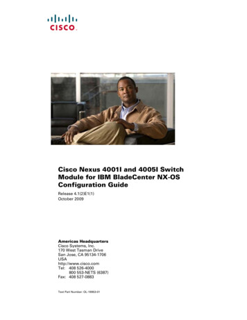
Figure 1-9. Dual Tone Multi-FrequencyWhen you pick up your telephone handset and press the digits (as shown in Figure 1-9), the tone that passesfrom your phone to the central office switch to which you are connected tells the switch what number you wantto call.ISDN uses another method of signaling known as out-of-band . With this method, the signaling is transportedon a channel separate from the voice. The channel on which the voice is carried is called a bearer (or Bchannel) and is 64 kbps. The channel on which the signal is carried is called a data channel (D channel) and is16 kbps. Figure 1-10 shows a Basic Rate Interface (BRI) that consists of two B channels and one D channel.Figure 1-10. Basic Rate InterfaceOut-of-band signaling offers many benefits, including the following: Signaling is multiplexed (consolidated) into a common channel.Glare is reduced (glare occurs when two people on the same circuit seize opposite ends of that circuitat the same time).A lower post dialing delay.Additional features, such as higher bandwidth, are realized.Because setup messages are not subject to the same line noise as DTMF tones, call completion isgreatly increased.19
In-band signaling suffers from a few problems, the largest of which is the possibility for lost tones . This occurswhen signaling is carried across the voice path and it is a common reason why you can sometimes experienceproblems remotely accessing your voice mail.Network-to-Network SignalingNetwork-to-network communication is normally carried across the following transmission media: T1/E1 carrier over twisted pairT1 is a 1.544-Mbps digital transmission link normally used in North America and Japan.E1 is a 2.048-Mbps digital transmission link normally used in Europe. T3/E3, T4 carrier over coaxial cableT3 carries 28 T1s or 672 64-kbps connections and is 44.736 Mbps.E3 carries 16 E1s or 512 64-kbps connections and is 34.368 Mbps.T4 handles 168 T1 circuits or 4032 4-kbps connections and is 274.176 Mbps. T3, T4 carrier over a microwave linkSynchronous Optical Network (SONET) across fiber mediaSONET is normally deployed in OC-3, OC-12, and OC-48 rates, which are 155.52 Mbps, 622.08Mbps, and 2.488 Gbps, respectively.Network-to-network signaling types include in-band signaling methods such as Multi-Frequency (MF) andRobbed Bit Signaling (RBS). These signaling types can also be used to network signaling methods.Digital carrier systems (T1, T3) use A and B bits to indicate on/off hook supervision. The A/B bits are set toemulate Single Frequency (SF) tones (SF typically uses the presence or absence of a signal to signal A/B bittransitions). These bits might be robbed from the information channel or multiplexed in a common channel (thelatter occurs mainly in Europe). More information on these signaling types is found in Chapter 3, "BasicTelephony Signaling."MF is similar to DTMF, but it utilizes a different set of frequencies. As with DTMF, MF tones are sent in-band.But, instead of signaling from a home to an end office switch, MF signals from switch to switch.Network-to-network signaling also uses an out-of-band signaling method known as Signaling System 7 (SS7)(or C7 in European countries). This section covers some of the benefits of SS7, however
small pieces (known as samples) and place them in an IP packet. Voice and data networking are complex technologies. This book explains how telephony infrastructure is built and works today, major concepts concerning voice and data networking, transmission of voice over data, and IP signaling protocols used to interwork with current telephony .