Transcription
SRMS History, Evolution and Lessons LearnedGlenn Jorgensen 1 and Elizabeth Bains. 2National Aeronautics and Space AdministrationEarly in the development of the Space Shuttle, it became clear that NASA needed amethod of deploying and retrieving payloads from the payload bay. The Shuttle RemoteManipulator System (SRMS) was developed to fill this need. The 50 foot long robotic arm isan anthropomorphic design consisting of three electromechanical joints, six degrees offreedom, and two boom segments. Its composite boom construction provided a light weightsolution needed for space operations. Additionally, a method of capturing payloads with thearm was required and a unique End Effector was developed using an electromechanicalsnare mechanism. The SRMS is operated using a Displays and Controls Panel and handcontrollers located within the aft crew compartment of the shuttle. Although the SRMS wasoriginally conceived to deploy and retrieve payloads, its generic capabilities allowed it toperform many other functions not originally conceived of. Over the years it has been usedfor deploying and retrieving constrained and free flying payloads, maneuvering andsupporting EVA astronauts, satellite repair, International Space Station construction, and asa viewing aid for on-orbit International Space Station operations. After the Columbiaaccident, a robotically compatible Orbiter Boom Sensor System (OBSS) was developed andused in conjunction with the SRMS to scan the Thermal Protection System (TPS) of theshuttle. These scans ensure there is not a breach of the TPS prior to shuttle re-entry.Ground operations and pre mission simulation, analysis and planning played a major role inthe success of the SRMS program. A Systems Engineering Simulator (SES) was developedto provide a utility complimentary to open loop engineering simulations. This systemprovided a closed-loop real-time pilot-driven simulation giving visual feedback, display andcontrol panel interaction, and integration with other vehicle systems, such as GN&C. It hasbeen useful for many more applications than traditional training. Evolution of thesimulations, guided by the Math Model Working Group, showed the utility of input frommultiple modeling groups with a structured forum for discussion.There were many uniquedevelopment challenges in the areas of hardware, software, certification, modeling andsimulation. Over the years, upgrades and enhancements were implemented to increase thecapability, performance and safety of the SRMS. The history and evolution of the SRMSprogram provided many lessons learned that can be used for future space robotic systems.1Shuttle Division Chief Engineer for the, Automation, Robotics and Simulation Divison, NASA-JSC, 2101 NASAParkway, Houston,77058.2Integrated Analysis Manager, Automation, Robotics and Simulation Divison, NASA-JSC, 2101 NASA Parkway,Houston,77058 and AIAA Associate Fellow.1American Institute of Aeronautics and Astronautics
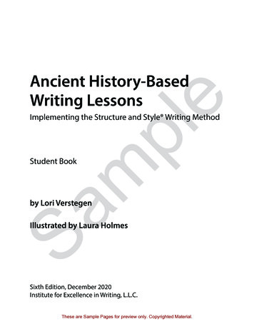
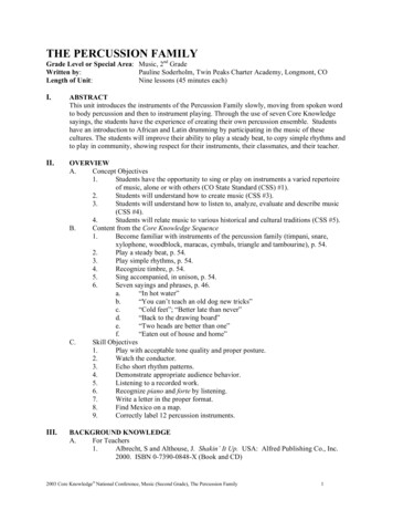
I. System Description and Evolution of the Shuttle Remote Manipulator SystemTHE fundamental requirement of the Shuttle Remote Manipulator System (SRMS) was to deploy and retrievepayloads to and from space. To accomplish this mission, the system that was developed consisted of ananthropomorphic manipulator arm located in the shuttle cargo bay (shown in Figure 1), cabin equipment to providean interface to the main shuttle computer, and a human interface to allow an astronaut to control arm operationsremotely.Figure 1. SRMS in the pre-cradle position looking aft in the shuttle payload bayA. Hardware OverviewThe manipulator arm consists of three joints, two arm booms, an end effector, a Thermal Protection System, anda closed-circuit television system. Figure 2 breaks down the primary SRMS components. The arm joints included ashoulder joint with two degrees of freedom (yaw and pitch), an elbow joint with one degree of freedom (pitch), anda wrist joint with three degrees of freedom (pitch, yaw, and roll). Each joint degree of freedom consists of a motormodule driving a gear box to effect joint movement and appropriate local processing to interpret drive commandsoriginating from the cabin electronics.The cabin electronics includes a displays and controls subsystem that provides the human-machine interface toallow a crew member to command the arm and view displays of appropriate information, including arm position andvelocity, end effector status, temperature, and caution and warning information. Additionally, in the displays andcontrols subsystem, two hand controllers allow man-in the-loop control of the end point of the arm. The main armprocessor is the manipulator controller interface unit (MCIU) that is also part of the cabin electronics. It handles alldata transfer between the arm, displays and controls panel, and the main shuttle computer. The main shuttlecomputer processes commands from the operator via the displays and controls panel; receives arm data to determinereal-time position, orientation, and velocity; and then generates rate and current limit commands that are sent to thearm-based electronics. The arm is thermally protected with specially designed blankets to reduce the susceptibility2American Institute of Aeronautics and Astronautics
of the hardware to the thermal extremes experienced during spaceflight and has an active thermostatically controlledand redundant heater ntrollerOverhead and Aft Flight DeckWindow ViewsTV MonitorsDisplay &ControlPanelAft Flight DeckRMS Work StationManipulatorControlInterface Unit(MCIU)GPC, CRT Monitorand KeypadWrist Cameraand Sideview Camera*Elbow Cameraon Pan Tilt UnitManipulator*Sideview camera shown in Figure 4.3-7Figure 2. Primary SRMS Components (Source – Reference 1)The closed-circuit television system consists of three cameras. A color camera on a pan/tilt unit near the elbowjoint was used as a situational awareness camera for the SRMS operator. A second camera in a fixed location on thewrist joint was primarily used to view a grapple fixture target when the arm was capturing a payload. A third cameracalled the SRMS Side-view Camera was added after the Columbia accident. This was fixed on the inboard side ofthe wrist joint and was used as a situational awareness camera when the SRMS was performing Shuttle ThermalProtection System inspections with the Orbiter Boom Sensor System (discussed later).Self-checks exist throughout all the Shuttle Robotic Arm electronics to assess arm performance and applyappropriate commands to stop the arm, should a failure occur. Caution and warning displays provide the operatorwith insight into the cause of the failure and remaining capability to facilitate the development of a workaroundplan.B. SRMS Operating ModesThe operating modes of the SRMS included Automatic modes, Manual Augmented modes, Single drive, Directdrive and a Back-up drive. Auto, Manual Augmented, and Single drive mode were supported with the main Shuttlecomputer and included servo joint rate control. Maximum joint rates were determined pre-flight and varied based onthe payloads being handled. Direct and Back-up drive modes were hardwired, reduced capability modes that applieda fixed voltage to the joint drive amplifier.Automatic modes included pre-programmed and operator commanded auto sequences. The pre-programmedsequences were developed prior to flight and loaded into the main shuttle computer. The operator commanded autosequence mode required the operator to input a final SRMS position and orientation before arm motion wasinitiated. Auto sequences were used primarily for shuttle and payload surveys and lengthy repositioning maneuvers.3American Institute of Aeronautics and Astronautics
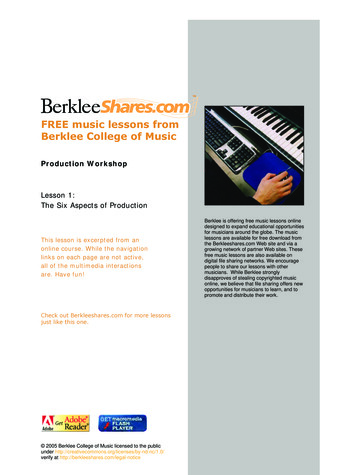
Manual Augmented modes allowed the SRMS operator to manipulate the SRMS position and orientation realtime using the Translational and Rotational hand controllers. The Point of Resolution and co-ordinate axes could bevaried depending on the operation being performed. This mode was used for grappling, berthing and un-berthingpayloads, track and capture of free flying payloads, and coarse positioning of the SRMS.Single joint drive allowed the operator to control each joint individually. This mode was used primarily to cradleand un-cradle the arm, and for fine positioning of the SRMS.Direct and Back-up drive modes were used for contingency arm motion should computer supported modes belost. They allowed only single joint control.C. The SRMS End EffectorThe interfacing end of the Shuttle RoboticArm is equipped with an electromechanicalEnd Effector. Figure 3 shows a picture of theEnd Effector on the end of the SRMS wristjoint. The wrist camera/light assembly is alsoshown. The End Effector is the equivalent toa human hand and is used to grapple apayload fitted with a specially designedinterface known as a grapple fixture. Apicture of a grapple fixture is shown inFigure 4.The grapple fixture includes a grapplepin, a target, and three alignment cams thatmate to cam lobes on the End Effector. TheEnd Effector uses a three cable snaremechanism that closes around the grapple pin(see Figure 5). Once grappled to the pin, thesnare mechanism is drawn inward into themain body of the End Effector to “rigidize”the payload to the SRMS. The cams ensureFigure 3: SRMS End Effector and Wrist Camera /Lightthere is no End Effector/Grapple fixture(Source – Reference 1)motion once the payload is captured.The standard grapple fixture is called aFlight Releasable Grapple Fixture, since it isequipped with a mechanism that can beGrapple Targetactivated by an EVA crewman to release thegrapple pin should the End Effector fail whilegrappled to a payload.The End Effector is also equipped withGrapple Pinan electrical connector called a SpecialPurpose End Effector (SPEE) connector. Thisconnector is fed with sixteen power and datalines from a cable harness routed along thelength of the SRMS. This connector can mateto a specially designed grapple fixture calledan Electrical Flight Grapple Fixture (EFGF).When captured, a payload equipped with anEFGF can be sent power and data signalsthrough the SRMS cable harness. A switchFigure 4: Grapple Fixture (Source – Reference 1)panel within the Shuttle was configured toprovide these signals.To track and capture a payload requiredthe use of the grapple fixture target inconjunction with SRMS wrist camera. Thecamera is oriented to allow a straight on view of the target. The camera video was displayed to the crew in the aft4American Institute of Aeronautics and Astronautics
flight deck, and helped the crew properlyposition the end effector relative to thegrapple fixture prior to capturing a payload.An overlay on the CRT display was used toaid the crewman in determining when theEnd Effector was over the grapple pin andready for capture. The SRMS wasmaneuvered to position the camera view ofthe grapple fixture target within theboundaries of the overlay. When satisfiedwith the relative position of the EndEffector to the grapple fixture target, thecrew used a switch on the Rotational HandController to capture and secure thepayload. The End Effector could beoperated in either automatic or manualmodes. In automatic mode the rigidizecommand would be initiated automaticallyafter the snares were closed around thegrapple pin. This was the standard mode ofoperation. Manual mode required thecrewman to input the snare close andrigidize commands separately.Figure 5: End Effector Snaring a Grapple Pin (Source –Reference 1)II. SRMS History of OperationsThe SRMS first flew on STS-2, and by the end of the Shuttle program it had flown a total of ninety-one missions.While originally envisioned only for satellite deployment and retrieval, the utility of a robotic arm for other tasksquickly became clear. Over the life of the program the SRMS evolved into an indispensible tool not only for satellitedeployment and retrieval, but was used extensively for satellite rescue and repair, as an EVA platform, InternationalSpace Station construction, shuttle and payload bay surveys, as well as a host of contingency operations.There were only three on orbit failures in the history of the SRMS program and only one of these failuresprevented completion of the mission. This was STS-41B when the wrist yaw motor commutator failed causing lossof all primary modes of operation. The payload scheduled to be deployed (the SPAS satellite) had to remain in thepayload bay. The second failure was on STS-51I when the power to the elbow joint electronics was shorted toground. The crew managed to complete payload operations using back-up drive for the elbow joint and single jointdrive for the other joints. The third failure was due to an incorrectly installed SPEE connector that prevented powerand data transfer to the payload (EURECA satellite). The satellite was berthed and the data transfer took place via apayload bay connector.Other less significant failures were experienced, and these were all worked by the ground team and the crew toallow completion of the mission with no loss of functionality in the SRMS. The reliability of the SRMS in its thirtyyear history is testament to the excellent design, manufacturing and testing teams, and to the ground supportpersonnel working with the rest of the shuttle team. The SRMS has proven its worth and has provided a blue printfor future robotic arms in space.A. Satellite Deployment, Retrieval, and ServicingThe list of satellites that were deployed and retrieved by the SRMS is long and impressive. The heavy liftcapability of the Shuttle combined with the capabilty of the SRMS allowed unique satellite missions to be designedthat were not previously possible. The retrieving capability of the SRMS made on-orbit repair and maintenance ofsatellites a reality for the first time.Figure 6 is a picture of the SRMS deploying the Gamma Ray Observatory (GRO) on STS-37. Other payloads ofnote deployed by the SRMS include the Earth Radiation Budget Satellite (ERBS) on STS-41G, and the UpperAtmosphere Research Satellite (UARS) on STS-48.5American Institute of Aeronautics and Astronautics
The majority of payloads deployed werealso retrieved by the SRMS. The firstsuccessful capture of a free flying payloadwas on STS-7 when the SPAS-1 satellite,originally deployed earlier in the mission, wascaptured and berthed in the payload bay bythe SRMS. Other deployments and capturesinclude SPARTAN on STS-51G, the PlasmaDiagnostics Package (PDP) on STS-51F, andthe SPAS-2 payload on STS-39. The LongDuration Exposure Facility (LDEF) wasdeployed on STS-41C and retrieved on STS32 (see Figure 7). The European RetrievableCarrier satellite (EURECA) was deployed onSTS-46 and retrieved on STS-57.The SRMS also played the primary role inrescuing malfunctioning satellites. Forexample, during STS-41C, it was used tograpple and berth the spinning SolarMaximum Mission satellite (Solar Max). Ithad been deployed in 1980 and had beenfitted with a grapple fixture to allow capturewith the SRMS. The track and capturecapability of the SRMS was put to the testdue to the high spin rate of Solar Max. TheSRMS was used on STS-51A during theretrieval of two malfunctioning comsats,Palapa B2 and Westar VI, which weresubsequently refurbished on Earth and reflown. One of the more notable SRMSaccomplishments was the deployment of theHubble Space Telescope (HST) on STS-31 inApril, 1990. This was followed by foursuccessful HST servicing missions (STS-61in 1993, STS-103 in 1999, STS-109 in 2002,and STS-125 in 2009) during which theSRMS was used to retrieve, repair andredeploy the space telescope. The finalservicing mission, STS-125, is expected toextend the life of the HST to 2014.Figure 6. STS-37 - Deploying the Gamma Ray ObservatoryFigure 7: Maneuvering the Long Duration Test Facility onSTS-32B. Extra Vehicular Activity (EVA) PlatformA mobile work platform for EVA astronauts became one of the most important uses for the SRMS. The arm wasused extensively in this capacity, both for pre-planned operations and for contingency EVA’s planned real-time thatwere needed for inspection or repair. The EVA crewmember could be mounted on a portable foot restraint attacheddirectly to the SRMS, or he could be mounted to the Manipulator Foot Restraint (MFR) that was grappled by theEnd Effector, or the crewman could simply grab the EVA handhold attached to the End Effector. The arm operatorinside the shuttle could easily position the EVA crewmember anywhere within the reach capability of the arm. Thestable platform provided by the SRMS allowed the crewman to perform tasks much easier than if he were freefloating. Radio communication between the EVA crewman and the arm operator enabled quick repositioning as6American Institute of Aeronautics and Astronautics
required. Tool stanchions and holderswere developed to aid in the repair andmaintenance activites. There are manyexamples during the life of the Shuttleprogram where the SRMS was used tosupport EVA, but none provide moreconcrete evidence of the value of arobotic arm as an EVA platform thanthe HST repair missions.The Hubble Space Telescope,deployed on STS-31 (1990), gave theworld a perspective of outer spacenever before seen. The first servicingmission repaired a problem with thetelescope’s main lens assembly. Thesubsequent missions replaced andenhanced onboard instrumentation.This improved the accuracy andextended the life of HST. Figure 8shows an EVA crewman on the end ofthe SRMS preparing for a Hubblerepair task. More than any otherpayload, the Hubble servicing missionsdisplayed to the world the uniquecapabilities of the SRMS.Figure 8: Hubble Space Telescope EVA Repair Work on STS-61C. The Era of Space Station ConstructionThe SRMS was the primary mechanism used for early International Space Station (ISS) construction. During thelater stages when the ISS was so large that the SRMS could not reach many berthing locations, the SRMS was usedin conjunction with theSpace Station RemoteManipulatorSystem(SSRMS) to complete theconstruction. In fact, theSRMS served as the proofof concept for the SSRMS,and many of the designfeatures, capabilities andoperations of the SRMSwere used in the design anddevelopmentoftheSSRMS. Figure 9 showsthe ISS P5 Truss segmentbeing handed off on STS105. ISS elements thatwere handled by the SRMSincluded Nodes 1,2 and 3,the US Laboratory Modulethe Space Station Airlock,nine truss segments, manyFigure 9: Handing off the ISS P5 Truss Segment from SRMS to SSRMSof which contained solarpanels for power to the station; and the Space Station Remote Manipulator System (SSRMS). These activitiesrequired some modifications to the SRMS itself, as well as the addition of systems to enhance alignment and7American Institute of Aeronautics and Astronautics
berthing operations. During the preliminary planning, studies evaluated the adequacy of the SRMS to handle theanticipated payload operations envisioned for the space station construction. These studies determined that armcontrollability would not be satisfactory for the massive payloads the arm would need to manipulate. Redesigningthe Servo Power Amplifiers (part of the Arm Based Electronics) in each joint provided the necessary controllability.Also, the addition of increased self-checks assured better control of hardware failures that could cause hazardous onorbit conditions. During the process of assembling the space station, enhanced berthing cue systems were necessaryto mate complicated interfaces that would need to transmit loads and maintain a pressurized interior. The complexityand close tolerance of mating parts led to the development of several berthing cue systems, such as the space visionsystem and the centerline berthing cue system, to enhance the crew’s ability to determine relative position betweenmating modules.D. Return to Flight After the Columbia Accident – The Orbiter Boom Sensor SystemDuring the launch of the Space Shuttle Columbia on STS-107 (2003), a piece of debris hit the shuttle, causing arupture in the Thermal Protection System that is necessary for re-entry into Earth’s atmosphere, thereby leading tothe Columbia accident. The ramifications of this breach in the shuttle’s Thermal Protection System changed the roleof the SRMS substantially for all post-Columbia accident missions. Development of the robotically compatible 50-ftOrbiter Boom Sensor System (OBSS), carried on the starboard mai nipulator positioning mechanisms, provided ashuttle inspection and repair capability that addressed the Thermal Protection System inspection requirement forpost-Columbia Return toFlight missions. Figure10 shows the OBSSgrappled by the SRMS.Modification of theroboticarmwiringprovided power and datacapabilities to supportthe inspection camerasand lasers at the tip ofthe inspection boom.Twoshuttlerepaircapabilitieswereprovided in support ofthe Return to Flighteffort. The first scenariorequired the SRMS,grappled to the spacestation, to position theshuttle and the spacestation in a configurationFigure 10: The SRMS Grappled to the Orbiter Boom Sensor Systemthat would enable a crewmember on the SpaceStation Robotic Arm to perform a repair. This was referred to as the Orbiter Repair Maneuver (ORM). The secondrepair scenario involved the Shuttle Robotic Arm holding the boom with the astronaut at the tip.All of the post-Columbia-accident missions employed the SRMS and Orbiter Boom Sensor System combinationto survey the shuttle for damage. The SRMS and OBSS were used to inspect all critical Thermal Protection Systemsurfaces. After the imagery data were processed, focused inspections occasionally followed to obtain additionalimages of areas deemed questionable from the inspection. A detailed test objective on STS-121 (2006) demonstratedthe feasibility of having a crew member on the end of the OBSS grappled by the SRMS and performing actionssimilar to those necessary for Thermal Protection System repair. Test results showed that the integrated systemcould be used as a repair platform and that the system was controllable with the correct control parameters, goodcrew training, and proper extravehicular activity procedures development.In support of shuttle repair capability using the Orbiter Repair Maneuver described earlier, the simulation model ofthe SRMS was updated to evaluate the handling of the space station as a “payload”. This heavy payload modelupdate proved useful when it was decided to repair the Hubble Space Telescope on STS-125. This is because after8American Institute of Aeronautics and Astronautics
the Columbia accident, a method of crew rescue was mandatory for all shuttle flights. A “Launch on Need” shuttlewas manifested for crew rescue should the shuttle on orbit sustain damage that would prevent re-entry. Given thatthe space station would not be available for crew rescue for the final Hubble servicing mission, the SRMS would beused to grapple the failed Shuttle. For the crew from the disabled shuttle to get to the rescue shuttle, the ShuttleRobotic Arm would act as a path for crewmen to transfer between the two vehicles. The updated SRMS simulationfor heavy payloads proved its worth when developing and validating this rescue scenario. Fortunately, neither ofthese repair/rescue capabilities—Orbiter repair maneuver or Hubble rescue— ever had to be used.III. Unique Challenges in the Development of the SRMSA. Mechanical DesignAs with all space systems, a tradeoff between mass and strength/stiffness had to be considered in the mechanicaldesign of the SRMS. With stiffness a primary consideration along with low mass, the material chosen for thebooms of the SRMS was a carbon composite material. In addition to stiffness, the high strength to weight ratio ofcarbon composite makes it ideal for space applications.Additionally stiffness was the driver in the design of the joints. The elbow joint, having only one degree offreedom, could not relieve forces and moments acting in off-axis directions, so strength was also a primary driver inits design. The joint construction was primarily fabricated aluminum housings, with some steel and titanium forhigher load bearing components. The gears were made from Carpenter Custom 455 steel, an exceptionally highstrength material (reference 1).The joint actuation design was electro-mechanical using brushless DC motors and high ratio gear boxes.Identical motors were used in every joint to minimize qualification requirements. Hydraulic joints were consideredhowever the potential for contamination from hydraulic fluid leakage eliminated this option. The choice to userelatively small motors driving the joint through a gear box, instead of larger motors in a direct drive configuration,was driven by the need to reduce weight. The gear ratios were adjusted based on the motor torque characteristics,and the requirement for high forward and backdrive efficiency, low backlash, and high drive train stiffness(reference 1).Each gearbox was designed with two stages. The first stage was a high speed design and the gear reduction ratiovaried from joint to joint to meet the specific joint torque requirement. The second stage was identical in all jointsand was a planetary design that maximized the number of load paths and provided high stiffness and low backlash.Backdrivability was a key driver in the design of the joints. High external loads can result in forces and momentsapplied to the arm that exceed its structural capability. Joints that can be backdriven will reduce the potential forthis excessive loading. The back drivability requirement drove the need for high gearbox efficiencies.The efficiency and back drivability requirements led to problems in the manufacture of the gearboxes. Tighttolerances in manufacture are necessary to achieve the degree of backlash and friction required to meet the controlsystem requirements. Gears had to be chosen based on a "select-on-manufacture" program resulting in a low yieldrate and higher costs.To ensure the joints did not apply excessive loads when the joints were in forward drive mode, motor currentlimiting was implemented in the servo power amplifiers that provided the electrical power to the motors. Theforward and backdrive current limits were matched to the gearbox effieciencies. Thus dynamic conditions weresimilar in all four quadrants of the drive system.The joint motor was chosen to minimize weight and eliminate maintenance. The brushless design avoided thewear and tear of commutator brushes. The motor chosen was a frameless design, so it was assembled in a housingthat included the motor and commutator, plus a brake and a tachometer. The entire unit was called the motor moduleand was common to all six joints. To ensure servo stability when the motor was driving in a no load condition, aflywheel was added.Dynamic braking using the motor to decelerate the joint was also incorporated into the joint design. Thiseliminated the requirement to apply mechanical brakes each time a drive command was removed and preventedexcessive wear on the brakes. This was required to meet the life requirements (originally 10 years but extended asthe program evolved).The SRMS electronics had extensive Built-In Test Equipment (BITE) that detected potentially catastrophicfailures and automatically applied brakes to prevent joint runaway and inadvertent contact between the arm andexternal shuttle/payload structure. To reduce the potential to exceed the structural load limits of the arm under thesemalfunction conditions, the joints had to be backdrivable with the brakes applied. Thus the brakes had to be9American Institute of Aeronautics and Astronautics
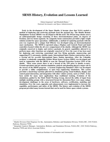
designed not only to provide a minimum holding torque, but also a maximum torque. It was found that the holdingtorque of the original brake material (an asbestos derivative) degraded with prolonged exposure to a vacuum due tomoisture loss. To solve this problem, the motor modules were refitted with ceramic brakes. Future space roboticsystems that are exposed to long term vacuum conditions should consider the use of ceramic brake material.B. Software-Singularity ManagementThe flight software (FSW) uses the Jacobian transformation matrix to relate joint rates to rates of the selectedcontrol point. When the SRMS is commanded to translate and/or rotate a defined point (tip of the SRMS or aselected point within the payload), the commanded joint rates are obtained using the inverse of the Jacobian. Nosolution for the commanded joint rates is available when the determinant of the Jacobian matrix is zero. There arethree conditions that cause this for the SRMS; these three conditions are shown in Figure 11.These singularities cause loss of one or more controlled degrees of freedom of the arm. With the wrist yaw jointabove the shoulder joints, Y translation commands cannot be accomplished (shoulder singularity). With the armstraight out, commands in the X direction in the EE mode are not possible (elbow singularity). With the wrist yawjoint 90 degrees from the arm pitch plane, some roll commands are not possible (wrist singularity).These singularities are managed within the RMS software algorithms. The arm is driven through the shoulder andwrist singularities by the software in the automatic and manual modes. During software handling, the arm maydeviate slightly from its commanded trajectory. The most dramatic deviation occurs if the operator commands a Ytranslation through the shoulder singularity. When the wrist yaw joint is 3 feet from being directly over theshoulder joint, the arm is re-oriented to drive in a circle around the singularity and then continues the Y translation.SINGULARITYTRANSLATION(a) WRIST YAW IN LINE WITH SHOULDER YAW AXIS SINGULARITY OCCURS WHEN THEWRIST YAW JOINT IS DIRECTLY ON THE SHOULDER YAW AXIS.ZoYoXoFXoZoYoXo(b) PLANAR PITCH JOINT SINGULARITY OCCURS WHEN THE WRIST PITCH, ELBOW PITCH,AND SHOULDER PITCH AXES ARE IN COLINEAR.SINGULARITYROTATION90ºZoYoXo(c) WRIST GIMBAL L
capability, performance and safety of the SRMS. The history and evolution of the SRMS program provided many lessons learned that can be used for future space robotic systems. 1. Shuttle Division Chief Engineer for the, Automation, Robotics and Simulation Divison, NASA-JSC, 2101 NASA Parkway, Houston,77058. 2