Transcription
H50/150 SMART SERIESWATER CHILLERSUSER MANUAL
H50/150 Smart – User ManualThank you for selecting our water chillers.We are sure that you will be completely satisfied with the performance ofthis new unit entering your laboratory. We invite you to read carefully thisuser manual and to keep it close to the instrument for convenient and fastconsulting. For any possible clarification or any request for assistanceplease contact either our local Representative or:LabTech SrlVia Fatebenefratelli, 1/524010 Sorisole (BG) ItalyTel 39 035 576614Fax 39 035 4729414Website www.labtechsrl.comE-mail marketing@labtechsrl.com2
H50/150 Smart – User ManualINDEX1 INTRODUCTION . 52 SAFETY RULES . 113 INSTALLATION. 133.1 POSITIONING THE INSTRUMENT . 133.2 ELECTRICAL REQUIREMENTS. 133.3 PLUMBING REQUIREMENTS . 143.4 FLUIDS . 154 OPERATION PROCEDURE . 164.1 LCD CONTROLLER . 164.2 TOUCH CONTROLLER . 174.2.1 MAIN INTERFACE . 174.2.2 MAIN MENU . 184.2.3 ALARMS . 204.2.4 START UP/SHUT DOWN . 224.2.5 PRESSURE REGULATION VALVE OF SMART H150. 225 MAINTENANCE . 245.1 RESERVOIR CLEANING . 245.2 CONDENSER CLEANING . 245.3 FILTER REPLACEMENT . 246 TROUBLE SHOOTING . 253
H50/150 Smart – User Manual6.1 UNIT DOES NOT START . 256.2 FLUID DOES NOT CIRCULATE . 256.3 INADEQUATE TEMPERATURE CONTROL. 256.4 LEAKAGE . 257 FLOW-CHART . 268 SERVICE . 27The information contained in this document may be the object of patent applications by LABTECH.The possession of this document does not confer any license rights in and to such patents.The following names are LABTECH trademarks throughout the world:LABTECHH50-500Smart H150-1000, Smart H150-1500, Smart H150-2100, Smart H150-3000H150-5000, H150-7000, H150-9000All Reproduction Rights Reserved4
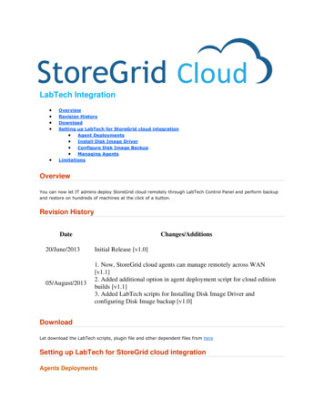
H50/150 Smart – User Manual1. INTRODUCTIONH50CONTROL PANELThe controller panel consists of the following keys:ActualTemperatureAlarmCooling IndicationSetpointWL Low Liquid Level AlarmTemperatureWorking State IndicationValue IncreaseBacklight On/OffValueDecreaseFRONT VIEWThe front panel consists of the following parts:Power SwitchControl PanelPressure GaugeLateral Air Flow5
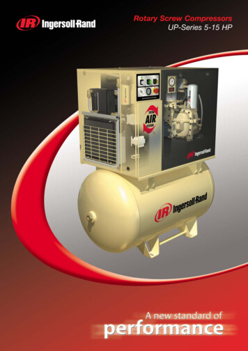
H50/150 Smart – User ManualREAR VIEWThe rear panel consists of the following parts:Electrical SocketLiquid Supply ConnectionLiquid Return ConnectionLiquid DrainSPECIFICATIONThe H50 series recirculating water chiller is designed to provide continuous supply of coolingfluid at a constant temperature and flow rate. The unit consists of an air-cooled refrigerationsystem, a plate heat exchanger, a recirculating pump, a reservoir and a microprocessortemperature controller.Technical specification:ModelH50-500H50-500/115V/DFTemp. control range-5 35 Temp. control modePIDCooling modeCompressor coolingTemp. stability 0.3 RefrigerantR134ACooling capacity/W500W@25 Pump capacity3L/min@10psiReservoir 480 250 500mmNOTE: the value of temperature stability is tested in standard operating mode.6
H50/150 Smart – User ManualSMART H150CONTROL PANELTouch controller H150 Series:TemperatureFRONT VIEWControllerLiquid LevelIndicator7
H50/150 Smart – User ManualREAR VIEWFuse holderPressure Regulation ValveElectrical SocketLiquid Return ConnectionLiquid Supply ConnectionLiquid Drain8
H50/150 Smart – User 50-2100NSLTH150-3000NS8 35 -20 35 8 35 8 35 -20 35 8 35 Temp. control rangeTemp. control modePIDCooling modeCompressor coolingRefrigerantR134ATemp. stability 0.1 1000W@25 Cooling capacity1000W@25 1500W@25 2100W@25 100W @-15 2100W@25 3000W@25 200W @-15 Pump capacity5L /min5L /min5L /min13L /min13L /min13L /minReservoir volume2.2L2.2L3.5L3.5L3.5L3.5LRecirculating H150-5000N740x460x700H150-7000NTemp. control range8 35 Temp. control modePIDCooling modeCompressor coolingRefrigerantR404ATemp. stability 0.2 H150-9000NCooling capacity5000W@25 7000W@25 9000W@25 Pump capacity13L /min13L /min13L /minReservoir volume22L22L22LRecirculating xHmm)690x640x1100690x640x1100690x640x1100NOTE: the value of temperature stability is tested in standard operating mode.9
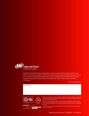
H50/150 Smart – User ManualMAGNETIC PRG & PR SERIES PUMP CAPACITY10
H50/150 Smart – User Manual2. SAFETY RULESGeneral InformationPlease read carefully this user manual before starting to use the instrument and follow itsprescriptions with the utmost care. This user manual is part of the delivery, hence must bealways kept together with the instrument on its working place.It is imperative that every person operating with this system has read and fully understood thismanual. The non-observance of the instructions contained herein or improper use may involvedamages/injuries that are not covered by product liability.Electrical safetyThe instrument has to be used within the rated voltage. Prior to use, please check if thewire is aged. In case of aged wires, please contact the after-sales service for inspection.It is forbidden to disassemble the instrument and to connect internal circuit parts, inorder to avoid a short circuit or open circuit.Fire safetyNumerous reagents are flammable and explosive. When the solvent vapor concentrationreaches a certain level, it would be flammable and could cause fire. The instrumentshould be kept away from the sources of ignition and high temperature places. If thereis solvent pungent smell, carefully check whether there is gas or liquid leakage, andturn off the power.Chemical safetyThe instrument is an instrument for organic chemical sample pretreatment. The involvedchemical solvents have harmful effects on the human health. Despite the instrument isfully closed and features full vent design, it is recommended to pay attention to thepersonal safety during the use. Regular check of liquid waste barrels as well as workingconditions of the vent fan are required to avoid the risk of leakage caused by corrosion and toavoid the formation of organic solvent vapors affecting operators’ health. If there is a fault,please contact the after-sales service.11
H50/150 Smart – User ManualRecommendationNever place the unit in a location where excessive heat, moisture, or corrosive materials arepresent.The unit construction provides extra protection against the risk of electrical shock by groundingappropriate metal parts. The extra protection may not function unless the power cord isconnected to a properly grounded socket. It is the user’s responsibility to assure that a properground connection is provided.Never connect the inlet or outlet fitting to your building water supply or any water pressuresource.Never use flammable or corrosive fluids with this unit.Do not use automotive antifreeze. Commercial antifreeze contains silicates that can damagethe pump seals. Use of automotive antifreeze will void the manufacturer’s warranty.Transport the unit with care. Inclination angle must be less than 60 degrees otherwise therefrigeration system could be damaged. Sudden jolts or drops can damage the refrigerationsystem.Pay attention to all warning labels and never remove them.Never operate a damaged or leaking equipment.Never operate the unit without the cooling fluid in the reservoir.Always turn off the unit and disconnect the power cord from the power source beforeperforming any service or maintenance procedure or before moving the unit.Never operate the equipment with a damaged power cord.Performance of installation, operation or maintenance procedure other than those described inthis manual may result in a hazardous situation and may void the warranty.Never use water (including distillated and deionized) in units installed in environments wheretemperatures go down below 5 C. We recommend 1:1 mixture of water and glycol to avoidliquid freezing.12
H50/150 Smart – User Manual3. INSTALLATION3.1 POSITIONING THE INSTRUMENTThe unit should be located in a clean environment where ambient temperature is between 10 and 35 (50 to 94 ). Max relative humidity: 80%, only indoor use, not for wet conditions.Max. operation altitude should be less than 2000 m.Never place the unit in a location where excessive heat, moisture, or corrosive materials arepresent.The unit has an air-cooled refrigeration system. The air is drawn through the front of the unitand discharged through the rear and side panels. The unit must be properly positioned so thatthe intake and discharge are not impeded. A minimum clearance of 1 meter (nearly 3 feet) onall vented sides is necessary for adequate ventilation. Inadequate ventilation will cause areduction in cooling capacity and, in extreme cases, compressor failure.Excessively dusty areas should be avoided and a periodic cleaning schedule should be done(see Chapter 8, Maintenance).The unit will retain its full rated capacity in ambient temperatures up to approximately 25 (77 ). Reduce the cooling capacity 1% for every 0.5 (1 ) above 25 (77 ), up to amaximum ambient temperature of 35 (94 ).13
H50/150 Smart – User Manual3.2 ELECTRICAL REQUIREMENTSThe unit provides extra protection against the risk of electrical shock by grounding appropriatemetal parts. The extra protection may not function unless the power cord is connected to aproperly grounded socket. It is the user’s responsibility to assure a proper ground connection isprovided.The following power options are pacity/AFusePowerDissipatedIPconsumptionheat NSThe unit is supplied with a European power cable. It is used to be connected with power supply.Plug the cord into socket and plug the rear into electric socket of the unit. Then the unit isready to be used.3.3 PLUMBING REQUIREMENTSH50The plumbing connections are located on the rear of the unit and labeled “SUPPLY” and“RETURN”. Remove the plastic protective caps from both plumbing connections. Install thebarbed adapters to these connections.Connect the fitting “SUPPLY” to the hose feeding the inlet of your application.Connect the fitting “RETURN” to the hose from the outlet of your application. Clamp all14
H50/150 Smart – User Manualconnections.Connect the ball valve to “DRAIN’’ position of the chiller and turn ball valve off.Never connect the fitting to the tap water supply or any water pressure source.It is important to keep the distance between the unit and the instrument to be cooled as shortas possible. Tubing should be straight and without bends. If diameter reductions must be made,they should be made on the inlet and outlet of the instrument to be cooled, not on the chiller.Smart H150The liquid plumbing connections are located on the rear of the unit and labeled “SUPPLY” and“RETURN”. The connections are 1/2-inch Female Pipe Thread. Units with 1/2-inch fittings aresupplied with 1/2-inch barbed adapters.Remove the plastic protective caps from both plumbing connections. Install the barbedadapters to these connections.Connect the fitting “SUPPLY” to the hose feeding the inlet of the instrument to be cooled.Connect the fitting “RETURN” to the hose from the outlet of the instrument to be cooled. Clampall connections. Connect the ball valve to “DRAIN’’ position of the chiller and turn ball valve off.Never connect the fitting to the tap water supply or any water pressure source.It is important to keep the distance between the unit and the instrument to be cooled as shortas possible. Tubing should be straight and without bends. If diameter reductions must be made,they should be made on the inlet and outlet of the instrument to be cooled, not on the chiller.When fittings have to be changed or the chiller is not used for a long period, be sure to drain allliquid out of the unit. Shut down the unit at first, then put a cup on the ground and disconnectthe fitting from the instrument cooled then let the fluid in the tank flow out into the cup anddisconnect the fitting on the chiller. Before positioning the unit in the storage be sure the draintap is closed.3.4 FLUIDSNever use flammable or corrosive fluids with this unit. Do not use automotive antifreeze.Commercial antifreeze contains silicates that can damage the pump seals. The use ofautomotive antifreeze will void the warranty.Fluids should be pure and contain no impurities such as grains. Otherwise, the impurities maydamage the pump. The use of unpurged fluids will void the warranty. Fluids should be replacedevery 6 months.Whenever fluid is replaced, please kindly add water cleanser into fluid to keep cleaning. ForH50-500/Smart H150-1000N/Smart H150-1000NLT/Smart H150-2100NS/Smart H150-2100NSLT/Smart H150-3000NS, the volume is 2 3 drops.For H150-5000/H150-7000, the volume is 5 6 drops.Note: please use mixture liquids of water 50% and glycol 50% when setpoint the is lowerthan 5 . Malfunctions caused by using incorrect cooling fluids will void the warranty.15
H50/150 Smart – User Manual4. OPERATION PROCEDURE4.1 LCD CONTROLLERCHANGE SETPOINTPress SET to enter the temperature set interface, useincrease the setpoint temperature.buttons to decrease oris a transposition key. Press SET again to save and quitthe temperature set interface.ALARMSA. High/low temperature alarmAlarm code L-A will be displayed and the buzzer alarm sound when the temperature isovershoot and 5 , or more, lower than the setpoint temperature. The refrigeration system willstop automatically.Alarm code H-A will be displayed and the buzzer alarm sound when the temperature isovershoot and 5 , or more, higher than the setpoint temperature. The refrigeration systemwill stop automatically.Switch off the chiller and restart it.B. Water level alarmWhen the water level is lower than the limit, the water level indicator “WL" will be displayedand the buzzer alarm sounds. The refrigeration system will stop automatically.Fill the water tank and the compressor will restart automatically after 1 minute.Note: the buzzer can be stopped by pressing any key.16
H50/150 Smart – User Manual4.2 TOUCH CONTROLLER4.2.1 MAIN INTERFACEHeating Output ValueCooling Output ValueDate and TimeRunning/Alarm statusSettable FunctionMeasurementsSettable FunctionRunning TimeMenua) Heating output indicator: the icon is switched ON when the unit is heatingb) Cooling output indicator: the icon is switched ON when the unit is coolingc) Real time measurements: process parameters are shown on real time. Liquid InLet andFlowrate parameters are options and can be removed from the display from FACTORYSETTINGd) Date and time: date and local time. Enter the SYSTEM SETTING window menu to modifythem.e) Running/Alarm status: shows the unit status between Running and Alarm. Available alarms:Temperature Over-range Liquid Level Gas Pressure Liquid Pressure Flow Rate SelfTesting High Temperature Low Temperature. Running mode indicates the unit is workingproperly.f) Running time: partial running time from the unit switch ON. When the unit is switched OFFthe timer is reset. Maximum time period: 10.000 hours.g) Menu: enter the main MENUh) Set temperature: shows the temperature setpoint value. Touch it to show theTEMPERATURE SETTING window.17
H50/150 Smart – User Manual4.2.2 MAIN MENUa) HOME: touch HOME button to return to the MAIN INTERFACE WINDOWb) HELP: touch HELP button to show the USER MANUALPARAMETER SETTINGReturn to MainInterfacePage SwitchingParameterSetpointParameter RangeNumeric Keypada) Page Switching: touch the area to change page under PARAMSETb) Parameter Setpoint: touch the value to activate the area (numbers will become yellow). Usethe numeric keypad to modify it. To confirm the new value touch OK button.c) Parameter Range: parameter setting range.d) Numeric Keypad: keypad can only be used when the value area is activated (yellow). Fornegative values touch the -/ button in advance. Once the new value is displayed press OK toconfirm (numbers will become white). Touch ESC button to cancel modifications and displaythe default value. Touch DEL button to delete the last digit selected.e) HOME: touch HOME button to return to the MAIN INTERFACE WINDOW18
H50/150 Smart – User Manualf) Parameters Setting pointValue of Temperature(-20.0 35.0 absolute(0.0 100.0 C)value Alarm is selected)Low temperature alarm (Active whenLTLtheTemperatureabsolutevaluevalueof(-20.0 HTL C)Alarm is whentheTemperature deviation value Alarm is(0.0 35.0 C)selected)Low deviation value of temperatureLDev(ActivewhentheTemperature(-35.0 0.0 C)deviation value Alarm is selected)HighHigh temperature range value(-20.0 70.0 C)LowLow temperature range value(-20.0 High C)LiquidPressureSetpointLiquid pressure value(0 10)BarLiquidFlowrateSetpointLiquid flow rate value(2 18) LPMTempLimitSYSTEM SETTINGDate/Time SettingFunction19
H50/150 Smart – User Manuala) Date/Time Setting: touch SETTING to modify date and time.b) Functions: touch desired values to change in the MAIN INTERFACE WINDOW.c) Communication COM: touch 1 to 8 COM to set the proper communication port with a targetinstrument.FACTORY RESETTouch YES button to restore default parametersCancel FactoryConfirm FactoryResettingResettingNote: always contact the LabTech Service Team for assistance before modifying orchanging the factory setting. Any malfunction due to improper setting is notcovered by the warranty.4.2.3 ALARMSa). TEMPERATURE ALARMTemperature Over-range Alarm: alarm code “----” is shown and the buzzer alarm sounds whenthe temperature measured in the liquid tank is lower than the low temperature limit or higherthan the high temperature limit, or the PT100 temperature sensor is open circuit / short circuit.The controller automatically shuts down the solenoid valve to stop liquid cooling.Temperature Absolute Value Alarm: when the temperature measured in the liquid tank is20
H50/150 Smart – User Manualhigher than High Limit Value Temperature (HTL) or lower than Low Limit Value Temperature(LTL), the buzzer alarm sounds and a warning alarmoris shown toindicate overcooling or overheating. HTL and LTL can be set in the PARAMSET – TAlarmwindow. The controller automatically shuts down the solenoid valve to stop liquid cooling.Temperature Deviation Value Alarm: when the temperature measured in the liquid tank ishigher than “Set value of temperature High deviation value (HDev)”, a warning alarmdisplays to indicate over heat. When the temperature measured in the liquid tank is lower than“Set value of temperature - Low deviation value (LDev)”, the buzzer alarm sounds and awarning alarm is shown to indicate over cooling. HDev and LDev can be set in the PARAMSET –TAlarm window. The controller automatically shuts down the solenoid valve to stop liquidcooling.TemperatureAbsolute ValueAlarmTemperatureDeviationValue AlarmNote:1) Switch OFF and ON the chiller to restart the normal unit working state after an alarm wasactivated.2) The Temperature Deviation Value Alarm is not working while self-testing process isperformed.3) The Temperature Deviation Value Alarm is not working after re-switch ON the unit or thetemperature set value changes.4) Before the compressor starts running, the Temperature Deviation Value Alarm is active,whereas the Temperature Absolute Value Alarm is valid.b). LIQUID LEVEL ALARM (Optional)21
H50/150 Smart – User ManualWhen the low liquid level sensor is activated for more than 10 seconds, the touch controllerdisplays liquid level alarm and the buzzer sounds. The controller automatically shuts down thesolenoid valve to stop liquid cooling. The unit turns back to normal state once the proper liquidlevel in the tank is reached.c). LIQUID PRESSURE ALARMWhen the pressure sensor detects that the liquid circuit pressure is higher than the set value high pressure limit or is lower than set value – low pressure limit for more than 5 seconds, thetouch controller shows liquid pressure alarmand the buzzer sounds. The unit turnsback to normal state once the proper liquid level in the tank is reached.d). LIQUID FLOW RATE ALARM (Optional)When the Switch Times alarm is activated, the touch controller shows flow rate abnormal alarmand the buzzer sounds if the flow switch has been off for more than 5 seconds.When the Water Flow Rate Analogy Amount alarm is activated, the touch controller shows flowrate abnormal alarm and the buzzer sounds if the flow sensor detects a flow rate higher thanset value high limit value or lower than set value – low limit value. The unit turns back tonormal state once the proper liquid level in the tank is reached.Note: the buzzer can be stopped by pressing any key.4.2.4 START UP/SHUT DOWNBefore starting the unit, double-check all electrical and plumbing connections.Open the top panel of the water tank, remove its cap and fill it with water by using a funnel.For H50 series, it is better to exhaust the air in the pump before the first use, just put thesupply tube in a container, switch on the unit for few seconds and leave flow out air and water.Place the switch of the unit to the up position, the controller will flash and the unit will start.Place the switch of the unit to the down position, the unit will shut down.NOTE: if you want to turn on the unit at once after shut down, please wait for 10seconds.4.2.5 PRESSURE REGULATION VALVE OF SMART H15022
H50/150 Smart – User ManualThe Pressure Relief Valve is used to adjust the unit’s fluid flow/pressure.NOTE: The valve is factory preset for the most common applications and normallyrequires no further adjustment. It is factory preset in order not to exceed 60 Psi(4.0Bar).Before adjusting the valve turn the unit off. Locate the circular regulation valve opening on therear of the unit.Turn the threaded stem fully counterclockwise.If the unit is not connected to the instrument to be cooled install a loop of hose equipped witha shut-off valve between the supply and return fittings.Turn the unit on.Use the pressure gauge to see the regulation valve setting.Turn the threaded stem valve clockwise. Continue until the gauge indicates 60 psi (4Bar) or thedesired setting.NOTE: the regulation valve may drip if the threaded stem is backed out too much.23
H50/150 Smart – User Manual5. MAINTENANCE5.1 RESERVOIR CLEANINGPeriodically inspect the fluid inside the reservoir. If cleaning is necessary, flush the reservoirwith a cleaning fluid compatible with the circulating system and the cooling fluid.The cooling fluid should be replaced periodically. Replacement frequency depends on theoperating environment and running time.Before changing the cooling fluid ensure that it is at a safe handling temperature.When fittings have to be changed or the chiller is not used for a long period, be sure to drain allliquid out of the unit. Shut down the unit at first, then put a cup on the ground and disconnectthe fitting from the instrument cooled then let the fluid in the tank flow out into the cup anddisconnect the fitting on the chiller. Before positioning the unit in the storage be sure the draintap is closed.5.2 CONDENSER CLEANINGFor proper operation, the unit needs to pull a substantial amount of air through a condenser. Abuildup of dust or debris on the fins of the condenser will lead to a loss of cooling capacity.The lower front of the unit has a one-piece grid assembly. Gently remove it using hands byprying. Use care not to scratch the paint.Periodic vacuuming of the condenser fins is necessary. The cleaning frequency depends on theoperating environment. After initial the installation we recommend a monthly visual inspectionof the condenser. After several months the cleaning frequency will be established.Use care when cleaning the condenser fins, they can easily bend.5.3 FILTER REPLACEMENTIf the water circuit of the unit is equipped with a filter system, please change the filter cartridgeperiodically.24
H50/150 Smart – User Manual6. TROUBLE SHOOTING6.1 UNIT DOES NOT STARTCheck the cord; ensure it is plugged in.Check the position of the circuit breaker on the front of the unit. It has to be in the upperposition.Check the voltage of power supply.NOTE: several starting attempts may be necessary on units with a Low Flow Switchand configured to shut down with a low flow fault.6.2 UNIT DOES NOT CIRCULATE FLUIDCheck the water level in the reservoir. Fill, if necessary.Check the instrument being cooled for restrictions in the cooling line.Check the pump strainer.Check the pressure gauge, adjust the relief valve as necessary.6.3 INADEQUATE TEMPERATURE CONTROLVerify the setpoint.If the temperature continues to rise, make sure the instrument to be cooled heat load does notexceed the rated specification.Make sure the air intake and discharge are not impeded and the ambient temperature does notexceed 35 .Make sure the condenser is free of dust and debris.6.4 LEAKAGEDue to vapor contained in the atmosphere, condensation may occur outside the tubes whenthe temperature of the refrigeration system is lower than the ambient: specially when thehumidity of the atmosphere is high, while the set point is lower, the condensation will be moreevident. To avoid such results, a dehumidifier should be use or the temperature set higher.25
H50/150 Smart – User Manual7. FLOW CHART26
H50/150 Smart – User Manual8. SERVICEThe LABTECH worldwide technical support network consists of highlytrained Field Service Engineers, Technical Support Specialists and ServiceCoordinators who are ready to quickly assist customers with answers andsolutions to service needs and application questions.For any possible clarification or any request for assistance please contacteither our local Representative or:LabTech SrlVia Fatebenefratelli, 1/524010 Sorisole (BG) ItalyTel 39 035 576614Fax 39 035 4729414Website www.labtechsrl.comE-mail service@labtechsrl.com27
The information contained in this document may be the object of patent applications by LABTECH. The possession of this document does not confer any license rights in and to such patents. The following names are LABTECH trademarks throughout the world: LABTECH H50-500 Smart H150-1000, Smart H150-1500, Smart H150-2100, Smart H150-3000