Transcription
De-orbit Descent and Landing Tipping PointProgram Final ReportJanuary 17th, 2022Prepared by:Stefan Bieniawski, Jon Polaha, Bryan Friia, and Michael ForrestBlue Origin, LLCKent, WAThe material is based upon work supported by the National Aeronautics and SpaceAdministration under Contract Number 80LARC19C0005.Any opinions, findings, and conclusions or recommendations expressed in this material arethose of the author(s) and do not necessarily reflect the views of the National Aeronautics andSpace Administration.
ABSTRACTThe purpose of this document is to provide a final report on the Deorbit, Descent, and Landing (DDL)Tipping Point program, a public-private partnership between Blue Origin and NASA that is partially fundedby NASA contract 80LARC19C0005. In this report we summarize the results of the entire contract,including recommendations and conclusions based on the experience and results obtained. Only theportions funded by the government with associated unlimited rights are documented in detail in thisreport. For the work funded by Blue Origin, summaries with unlimited rights are provided for context andcompleteness. The Blue Origin funded work exceeded 25% of the originally proposed total program costand included a mixture of hardware procurement and critical technology maturation.The scope of this document is a discussion of all the major tasks performed under the contract includingthe sensor flight demonstrations on New Shepard, the hardware in the loop lunar landing navigatordemonstration, and the ground testing of the Flash LiDAR hazard sensor. The contributions from themultiple NASA teams – Johnson Space Center, Langley Research Center, Goddard Space Flight Center,and Jet Propulsion Laboratory – are described along with the contributions from Blue Origin. Thisdocument is the Final Report for statement of work item 4.1.2.10 as Deliverable 5.8.Page 1 of 32
TABLE OF CONTENTSABSTRACT . 1LIST OF FIGURES .2LIST OF TABLES . 3ACRONYMS . 4REFERENCES . 51.Introduction . 6Background . 6Document Overview . 72.Sensors Demonstration Task . 8Task Overview . 8Summary of Sensor Flight Demonstrations . 12Flight 1: 13-October-2020 . 12Flight 2: 26-August-2021 . 14Conclusions and Recommendations . 163.Blue Origin Navigator – Lunar Variant Task .17Task Overview . 17Summary of Blue Origin Contribution . 17Demo Period Contributions . 17Demo Period Contributions . 18Summary of Jet Propulsion Laboratory Contribution . 19Technology Background . 19Demo Period Contributions . 20Demo Period Contributions . 21Summary of Other JPL Contributions under DDL Tipping Point . 21Summary of Hardware-in-the-Loop Demonstrations . 21Demo . 22Demo . 22Conclusions and Recommendations . 22Conclusions . 22Page 0 of 32
Recommendations for Future Work .234.Flash LiDAR Task .24Overview . 24Key Results and Findings . 24Conclusions and Recommendations .255.Program Level Conclusions and Recommendations . 26Conclusions .26Recommendations. 30Page 1 of 32
LIST OF FIGURESFigure 1: Infusion of Upgraded DDL Sensors Tested on New Shepard into Blue Moon. . 6Figure 2: Sensors and integration options being considered at the System Requirements Review. 9Figure 3: Maturity at the Preliminary Design Review showing feasible locations for all the sensors. 9Figure 4:The DDL Sensor payload chassis and supporting payload services subassemblies. . 10Figure 5: Locations of the DDL payload components on the PM. 11Figure 6: PM installation of the DDL Sensor payload chassis and sensor heads. . 11Figure 7: Vehicle altitude and velocity from Flight 1. . 12Figure 8: Vehicle altitude and velocity from Flight 2. . 14Figure 9: BlueNav-L Hardware-in-the-Loop Demonstration Configuration. . 18Figure 10: Elevation and map for the extended demonstration from pre-powered descent tolanding. Elevation relief (top), Rendered imagery (bottom). . 19Figure 11: Simulation of JPL Lander Vision System for lunar landing: coarse matching (left) and finematching (right). In each: camera image upper right, cropped reference map on left, and completemap with comparison regions shown lower right. Matched features shown in green. . 21Page 2 of 32
LIST OF TABLESTable 1: Summary of capabilities tested during DDL Tipping Point and major accomplishments. . 27Table 2: Blue Origin assessment of capabilities maturity based on testing during DDL Tipping Point. 28Page 3 of 32
ACRONYMSASCAdvanced Scientific Concepts, LLCBlueNavBlue Origin NavigatorCCCrew CapsuleCONCenter of NavigationCORContracting Officer RepresentativeCOTSCommercial Off the ShelfDDLDeorbit, Descent, and LandingDEMDigital Elevation MapGPUGraphics Processing UnitHWILHardware-In-the-LoopICDInterface Control DocumentIMUInertial Measurement UnitJSCJohnson Space CenterkgKilogram(s)kmKilometer(s)LaRCLangley Research CenterLiDARLight Detecting and RangingmMeter(s)m2Square Metersm/sMeters per SecondNASANational Aeronautics and Space AdministrationPL&HAPrecision Landing & Hazard AvoidancePMPropulsion ModulesSecond(s)SPLICESafe & Precise Landing - Integrated Capabilities EvolutionSRSuper ResolutionPage 4 of 32
REFERENCES[1]Utilizing Public-Private Partnerships to Advance Tipping Point Technologies, AppendixNumber: 80HDTR18NOA01-18STDM 001, Amendment 5, November 30, 2017.[2]“De-orbit Descent and Landing Tipping Point Flight 1 Summary Report,” January 15, 2021.[3]“De-orbit Descent and Landing Tipping Point Flight 2 Summary Report,” November 17, 2021.[4]“De-orbit Descent and Landing Tipping Point Flash Lidar Demonstration Final Report,” April16, 2021.[5]Bieniawski, S., et. al, “New Shepard Flight Test Results from Blue Origin De-Orbit Descentand Landing Tipping Point,” AIAA 2022-1829, Presented at AIAA SciTech 2022 Forum, SanDiego, CA, January 3-7, 2022, https://doi.org/10.2514/6.2022-1829.[6]Aaron, S., et. al, “Performance Analysis of Terrain Relative Navigation Using Blue Origin NewShepard Suborbital Flight Telemetry,” AIAA 2022-1830, Presented at AIAA SciTech 2022Forum, San Diego, CA, January 3-7, 2022, https://doi.org/10.2514/6.2022-1830.[7]Fritz, M., et. al, “Post-Flight Performance Analysis of Navigation and Advanced GuidanceAlgorithms on a Terrestrial Suborbital Rocket Flight,” AIAA 2022-0765, Presented at AIAASciTech 2022 Forum, San Diego, CA, January 3-7, 2022, https://doi.org/10.2514/6.20220765.[8]Amzajerdian, F., et. al, “Performance of Flash Lidar with real-time image enhancementalgorithm for Landing Hazard Avoidance,” AIAA 2022-2206, Presented at AIAA SciTech2022 Forum, San Diego, CA, January 3-7, 2022, https://doi.org/10.2514/6.2022-2206.Page 5 of 32
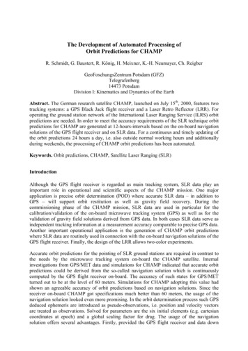
1.INTRODUCTIONBackgroundNASA Space Technology Mission Directorate “seeks aggressive technology development effortsthat may require undertaking significant technical challenges and risk to achieve a higher potentialpayoff. (SpaceTech-REDDI-2018)” Work completed was the result of a proposal submitted by BlueOrigin, LLC for award under the NASA Headquarters Space Technology Mission Directorate (STMD)NASA Research Announcement (NRA) entitled Space Technology Research, Development,Demonstration, and Infusion-2018 (SpaceTech-REDDI-2018)”.The NASA/Blue Origin 2018 De-orbit Descent and Landing (DDL) Tipping Point Program includesintegration of NASA developed technology into a Blue Origin, LLC state-of-the-art launch vehicle,New Shepard, providing opportunities to mature critical sensor technology and algorithms thatenable precision and soft landing.Figure 1: Infusion of Upgraded DDL Sensors Tested on New Shepard into Blue Moon.The testing was performed up to approximately 100 km altitude on-board the flight proven NewShepard vertical takeoff vertical landing suborbital vehicle. Figure 1 depicts the flight profile,expanding the flight envelope beyond previous NASA airborne tests (generally 1 km), capturing thefull range of operation for each DDL sensor. Figure 1 represents the proposed sensors for the flightdemonstrations, some of which, during the program, we learned were not robust or mature enoughto fly on New Shepard. Where appropriate they were still evaluated in ground tests. Blue Origin andNASA continue to use the flight data to anchor analyses and models and support follow-ondevelopment. The NASA-developed or commercial sensor suite will enable Blue Moon to preciselyland anywhere on the lunar surface, from the equator to the poles, from the rim of Shackleton craterto permanently shadowed regions, from the far side locations on the South Pole/Aitken basin tolunar lava tubes.This program has three high-level technology objectives:1.Demonstrate the performance of NASA-developed and contractor provided precisionlanding sensor and processing technology (including, but not limited to, Descent LandingComputer (DLC) and Navigation Doppler Light Detection and Ranging (LiDAR, NDL)) in anPage 6 of 32
2.3.operating envelope (altitude, velocity, and vehicle environments) from space environmentsthrough soft propulsive landing operations on a commercial vehicle (the New ShepardPropulsion Module)Demonstrate a commercial navigation system for safe and accurate lunar landings usingNASA-developed Terrain Relative Navigation (TRN) algorithms as part of a Hardware-inthe-Loop (HWIL) simulation environmentDevelop and demonstrate a Flash LiDAR prototype for hazard detection derived from NASAdeveloped Flash LiDAR sensor design and image processing softwareEach of these objectives advances a critical DDL capability by building on completed and ongoingNASA-led development efforts, including Mars 2020 Lander Vision System (LVS), AutonomousLanding and Hazard Avoidance Technology (ALHAT), CoOperative Blending of Autonomous LandingTechnologies (COBALT), and Safe & Precise Landing – Integrated Capabilities Evolution (SPLICE).Objective 1 removes the flight envelope limitations of currently available flight test vehicles (e.g.,helicopters, propulsive “hoppers”). Compared to previous flight tests, the New Shepard flight profileis similar to that of a lunar landing by increasing attainable altitude from 1 km to 100 km, increasingvertical velocity from 25 m/s to 900 m/s, and providing access to the space environment.Objective 2 lowers the cost of GN&C computing elements and sensor fusion, while addressing theprocessing requirements of fusing optical and LiDAR sensors (e.g., limitations identified duringCOBALT that prevented integration of NDL and LVS) and generating surface relative position andattitude navigation data in real-time. The resulting BlueNav-L hardware and simulation environmentwill facilitate development of Blue Moon landing concepts, operations, and requirements.Furthermore, sensor test data from Objective 1 can directly inform and be incorporated into thesesimulations to anchor results and increase fidelity.Objective 3 addresses desired improvements in Flash LiDAR performance identified as part ofALHAT, leveraging image processing software advancements. Compared to the ALHAT version, theLiDAR prototype to be demonstrated is expected to improve resolution by making use of the superresolution software. The super-resolution technique takes advantage of sub-pixel shifts betweenmultiple, low-resolution images of the same scene to construct a higher resolution image and isexpected to increase the effective image resolution of the Flash LiDAR by 4x to 8x. These sensorcapabilities enable generating a Digital Elevation Map (DEM) of 100x100m, with 10 cm resolution froman altitude of 1 km.With the Tipping Points, NASA “continues to embrace public-private partnerships to achieve itsstrategic goals for expanding capabilities and opportunities in space” to “deliver technologies andcapabilities needed for future NASA, other government agency, and commercial missions.” [1] Tohelp ensure commercial infusion of these space technologies, NASA requires the offeror to fund atleast 25% of the total project cost inclusive of any NASA costs. The contract mechanism is a firmfixed price, requiring all overruns of the industry portion to be covered by the offeror.Document OverviewThis integrated final report combines the summaries of the work completed under the three taskswithin the DDL Tipping Point program. In Section 3 we review the sensors flight demonstration taskthat included two successful flights on New Shepard with various landing sensors. In Section 4 wereview the testing of the Blue Origin lunar navigator that incorporated JPL’s Map RelativeLocalization software. In Section 5 we review the Flash LiDAR ground testing performed primarily byNASA Langley with support from Blue Origin. We conclude in Section 6 with the program levelconclusions and recommendations.Page 7 of 32
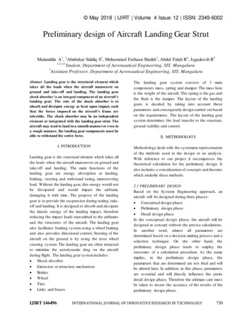
2.SENSORS DEMONSTRATION TASKThis section of the final report describes the work performed during the sensors flightdemonstration task consisting of two flights on the New Shepard launch vehicle with NASA andcommercial sensor payloads. We begin with an overview of the task followed by the results of theflight demonstrations. The overview describes the design development and key decisions regardingwhich sensor payloads ultimately made it to the flights. Both flights successfully demonstrated theutility of the New Shepard system. The flight profiles began from the ground, continued toapproximately 100 km altitude, and then returned for a propulsive landing of the Propulsion Module(PM) and a parachute landing of the Crew Capsule (CC). The tests expanded the flight envelope foreach DDL sensor beyond previous airborne tests (generally 1 km) and captured their full range ofoperation. We close with task level conclusions and recommendations. Additional details areavailable in References 2, 3, 5, and 7.Task OverviewAs seen in Figure 1, the original proposal proposed flight demonstration of NASA Langley’s NDL andLRA along with JPL’s LVS. All three were proposed as environmentally hardened versions of sensorspreviously flown on ALHAT or COBALT programs. These were ruggedized versions of the earlyCommercial Off the Shelf (COTS) hardware prototypes. Following award and during negotiation wewere able to take advantage of the developments under the NASA SPLICE program and adjusted theplanned sensors. We baselined for flight the next generation of the NDL in development at that timeat NASA Langley, preserved the ruggedized COTS LVS scope, and then added NASA JSC’s DescentLanding Computer (DLC) to the flight plan. We also decided to include at least preliminary designintegration of NASA Goddard’s Hazard Detection LiDAR. It is important to note none of these sensorshad yet been built and all required extensive design work to be performed in parallel to theintegration activity and preparation of the New Shepard Propulsion Module for the payloads.However, including these changes offered a substantial increase in the technology learning andpartnership between Blue Origin and NASA. The contract Authority To Proceed was 22-April-2019with a virtual kickoff held shortly thereafter.We performed a System Requirements Review (SRR) on 22-23-May-2019 which covered the sensorand launch vehicle interface requirements. The review was held in person at Blue Origin facilities inKent WA. Figure 2 shows the snapshot of the different sensors and the integration options beingconsidered at the time of the SRR. Extensive collaborative design work was performed over the nextfew months leading to the Preliminary Design Review 30-July-2019. The full day technical reviewheld at NASA Langley facilities in Hampton VA included defined expectations and was led by acombined Blue Origin/NASA technical evaluation committee. The purpose of the PDR was to confirmthe following activities had been completed to the appropriate level of maturity:1.2.3.4.Finalize locations for the NASA sensor elements on the PM4 vehicleDefine sensor interfaces to the level of maturity needed to achieve the program goals ofrecording integrated vehicle and sensor flight data setsPresent the high-level test scope for all program activities including the sensordemonstration effort and the ground demonstration taskPresent PDR-level maturation of the Hazard Detection LiDAR (HDL) and provide arecommendation on continuing integration and flight test within the programThe configuration at PDR is shown in Figure 3. We achieved the expectations of the PDR with somegating actions which were subsequently closed. A major decision was to remove the HDL fromfurther consideration. Another major accomplishment was finding feasible locations for the sensorPage 8 of 32
chassis and sensor heads on the PM using the transition tunnels and forward section. Work thenproceeded to detailed design.Figure 2: Sensors and integration options being considered at the System Requirements Review.Figure 3: Maturity at the Preliminary Design Review showing feasible locations for all the sensors.Page 9 of 32
The Critical Design Review (CDR) took place on 30-October-2019 at Blue Origin facilities in Kent WA.A combined Blue Origin/NASA Technical Evaluation Committee was formed to ensure thecoordinated set of review expectations were met. We reviewed the detailed design of the structuraland avionics accommodations on the New Shepard Propulsion Module along with the critical designmaturity of the NASA payload sensors. The build, operations, and test plans were also reviewed. Theexpectations were met and gated the program activity to build the flight hardware. Shortly after thereview, however, it became clear that ruggedizing the COTS hardware prototype of the LVS couldnot be made ready for flight on New Shepard. Note that this COTS hardware prototype wassignificantly different from the Mars 2020 LVS Vision Compute Element. A contract modificationexecuted on 13-December-2019 removed the LVS from flight and added replay of the DLC recordedIMU and camera imagery through the JPL software instead. This still supported the objective ofevaluating two different Terrain Relative Navigation applications now using a single common dataset. This also freed up a payload location on the Propulsion Module that was already past CDRmaturity and in build. Fortunately, Blue Origin had separately procured a commercial Doppler LiDARfrom Optical Air Data Systems (OADS) called the Optical Moon Proximity Sensors (OMPS) that couldbe qualified and installed in time for the flights. A rapid design cycle was able to update the designof the sensor chassis location and particularly the sensor head location.The sensor chassis and the supporting items such as batteries, payload controller, and switcheswere built-up in three separate assemblies. The three assemblies are shown in Figure 4 in thebenchtop testing configuration. The benchtop testing was performed to confirm the function of theelements and compliance with the interface definitions. Non-flight sensor heads were used asneeded for interface and functional verification as the flight versions and associated harnesseswere being installed on the vehicle in parallel to the benchtop testing. The testing also exercised theoperational procedures and was successfully completed 23-August-2020. The subassemblies andthe sensor head assemblies were installed on the PM for the integrated system testing and for thetwo flights. Each unit consists of a chassis located under the PM “table-top” and a sensor headlocated in the transition tunnel/ring fin support to provide view to the ground during launch anddescent. Figure 5 shows these installations in a CAD view and Figure 6 shows photos of them asinstalled. Also shown in the CAD view is the BlueNav IMU and navigator which provided the “truth”data and are located between the two sensor head assemblies. The installation included metrologyof the as-installed sensor head assemblies and a camera calibration and LiDAR beam findingactivity. These preparations ensured the highest possible accuracy and knowledge of the installedsensors. All integration and pre-launch test activities were completed 16-September-2020 and thesystem was ready for flight.Figure 4:The DDL Sensor payload chassis and supporting payload services subassemblies.Page 10 of 32
Figure 5: Locations of the DDL payload components on the PM.Figure 6: PM installation of the DDL Sensor payload chassis and sensor heads.Page 11 of 32
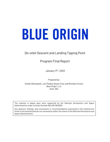
Summary of Sensor Flight DemonstrationsTwo flights of New Shepard with landing sensors installed were performed under the DDL TippingPoint collaboration. The first took place on 13-October-2020 and the second on 26-August-2021. Inbetween these dates significant updates and modifications were made to the NASA sensors recoverfrom anomalies or to enhance the quality and quantity of data obtained. No changes were made tothe vehicle side installations or software.Flight 1: 13-October-2020The first flight was successfully completed on 13-October-2020 at Blue Origin facilities in WestTexas. A first attempt of the flight was performed 24-September-2020 and the sensor payloadswere operated through their first power cycle prior to the scrub for reasons not related to the DDLpayloads. This attempt gave the team valuable practice in the launch operations, displays, andprocedures. Between the first attempt and the flight no changes were made to the DDL payloads;however, additional situational awareness aids specifically for the NASA personnel were madeavailable. One DDL payload specific constraint – requiring less than 30% cloud cover – was a concernduring the countdown and lead to a waiver. Blue Origin was responsible for providing the flightopportunity and delivering the associated trajectory truth data. These data included timing and keyevents, coordinate frames, and flight trajectory and attitude. These data and other aspects of themission are described in more detail in Reference 2. Blue Origin also provided the required interfacesand data needed to successfully operate the payloads throughout the flight. Blue Origin included inits scope data gathering from an additional commercial landing sensor, a Doppler LiDAR systemfrom Optical Air Data Systems. Based on analysis of the flight trajectory data, the PM met the missionrequirements and performed as expected. The detailed trajectory time histories are shown in Figure7. The PM achieved the 100km altitude objective and performed a propulsive landing.Figure 7: Vehicle altitude and velocity from Flight 1.The vehicle data was transmitted real-time and logged for detailed post-processing. The estimatederrors in the truth position are generally sub 0.1 m, 1-sigma for instance for the descent. Based onanalyses of the interface data, the PM met the expected mission environments for thermal andPage 12 of 32
power. The thermal environment was within the predicted range albeit on the colder side. The DLCand OMPS were not adversely affected; however, the NDL did experience issues. A clear field of viewfor the camera and LiDARs was provided during the flight and most critically on descent. Some dustwas observed in both ascent and descent recorded data for the commercial LiDAR. On ascent, lensflare was observed in the DLC camera images. The sensor payloads were successfully operatedduring the mission. NASA technical personnel were on-site and able to perform real-time monitoringof the payloads. In addition, the NASA Contracting Officer Representative (COR) was on-site and ableto make consolidated recommendations and review waivers as required. The post-flight data reviewand assessment indicates the sensors received the expected commands and were successfullyoperated. The NASA provided payloads included a large number of steps and checks that wererequired to operate them successfully. The commercial LIDAR from OADS called the Optical MoonProximity Sensor (OMPS) provided range and speed measurements using four telescopes. Collectedmeasurements were compared against a sensor model and the differences seen betweenmeasurements and predictions were within expectations.Reference 2 provides a detailed report of the NASA JSC findings from Flight 1. The DLC and sensorswere expected to process 400 Hz IMU data, 20 Hz NDL data, and 2 HZ TRN camera images. The IMUand NDL data were successfully processed at the expected rate. However, the camera image ratefor flight was 1Hz due to a firmware issue with the camera. The hardware performed throughout theflight and was robust to the thermal, vibration, and shock environments. The DLC included the coreflight executive software as well as multiple other applications. The software successfully achievedthe primary objective of interfacing with the camera, IMU, NDL, and host vehicle and recording thedata during flight. Issues with the timestamping were identified and the recorded data wascorrected. Changes were proposed for Flight 2 to correct the real-time performance of this primaryobjective. Due to the timing issue, the TRN, navigation, and guidance algorithms hosted on the DLCdid not perform as expected. Post-flight replay of the data through the software was, however, ableto show the expected performance, as detailed in Reference 2.Reference 2 provides the detailed assessment of Flight 1 by NASA Langley Research Center for theNDL. While NDL operated throughout the flight, the data quality was compromised by elevatedbackground levels which significantly limited the amount of valid range or Doppler speed datacollected. The elevated background levels resulted from the operational temperatures being morethan 20 C lower than those at which the background was gathered. Approximately fifteen secondsof navigation data during landing and a few seconds during ascent were valid. It was expected tocollect about 70 seconds of navigation data in this flight. Reference 2 provides detail on theoperational anomalies observed during the flight, presents the valid flight data, and identifies thecorrective actions that were pursued for Flight 2.Reference 2 documents the work performed by JPL to post-process the recorded DLC camera andIMU data through its pro
The NASA/Blue Origin 2018 De-orbit Descent and Landing (DDL) Tipping Point Program includes integration of NASA developed technology into a Blue Origin, LLC state-of-the-art launch vehicle, New Shepard, providing opportunities to mature critical sensor technology and algorithms that enable precision and soft landing. .