Transcription
PROCEDURESControl your Speed During Descent, Approach and LandingControl your Speed During Descent,Approach and LandingThis article is the conclusion of our theme of speed managementduring a flight, which began in Safety first Issue #18. We areentering into the descent phase. Our objective is to coverdescent from cruise altitude down toward the destination airportand prepare the aircraft for its approach and landing.This article aims to highlight how the reference, limit and operatingspeeds are useful during descent, approach and landing.It also provides a description of the tools that are available andoperational recommendations on how to manage the aircraftenergy during the last phases of flight.
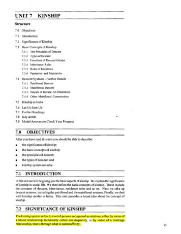
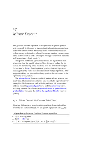
Safety First #24 July 2017Energy management, and as a consequence speed management,is critical during descent, approach and landing phases. An aircraftflying at cruise altitude, and at its cruise speed, has a lot of energyto dissipate before reaching its destination airport and to landwith an appropriate speed. Incorrect management of the speedin descent can result in excess-energy in final approach phase.This is shown to be a major cause of runway overrun events.MANAGING YOUR DESCENT,APPROACH AND LANDING:UNDERSTAND SPEEDSManeuvering speedsGreen dot isthe managed speedtarget in CONFCLEAN when theFMS approach phaseis activated.As for the previous flight phases, Green Dot, S and F speeds guide the flight crewduring descent and approach phases.Green Dot (GD) speed DefinitionGD speed (fig.1) is the engine-out operating speed in clean configuration.It provides an estimate of the speed for best lift-to-drag ratio.GD speed is the managed speed target in CONF CLEAN when the FMSapproach phase is activated. It is also the recommended speed to extendflaps to CONF 1 and for a holding in clean configuration.How is GD speed determined?Green Dot SpeedThe Auto Flight System (AFS) computes GD speed using the aircraft weight,based on the Zero Fuel Weight (ZFW) entered in the FMS during flight preparation,and the pressure altitude. The GD formula has been set up so that the resultingairspeed provides the best lift-to-drag ratio for a given altitude and aircraft weight,in clean configuration with one engine out.In some phases of flight, GD is computed to minimize drag and thus, the fuelconsumption (for example during the HOLD phase).(fig.1)Green Dot speed on the PFD speed scale007
PROCEDURESControl your Speed During Descent, Approach and LandingS and F speeds DefinitionS speed:In approach phase, S speed is the managed speed target, when in CONF 1 or 1 F.It is the recommended speed to select CONF 2.S SpeedIt is displayed as a green ‘‘S’’ on the PFD airspeed scale (fig. 2) and shown onlywhen the Slats/Flaps control lever is on position 1 (CONF 1 or 1 F).F speed:In approach phase, F speed is the managed speed target, when in CONF 2 or 3.It is the recommended speed to select CONF 3 when in CONF 2, and to selectCONF FULL when in CONF 3.(fig.2)S speed on the PFD speed scaleIt is displayed as a green ‘‘F’’ on the PFD airspeed scale (fig. 3) and shown onlywhen the Slats/Flaps control lever is in CONF 2 or 3 during the approach phaseand go-around.How are S and F speeds determined?S and F speeds are obtained using the Stall speed of the corresponding configuration(Vs1g) demonstrated during flight tests multiplied by a specific factor depending onthe aircraft type. Margins are kept with the Minimum Control speed at Landing (VMCL)determined during flight tests, and with the maximum speed with Flaps Extendedof the next configuration (VFE NEXT):S or F VS1G x factorF SpeedS k x VS1G CLEAN with 1.21 k 1.23FCONF2 k x VS1G CONF 2 with 1.38 k 1.47FCONF3 k x VS1G CONF 3 with 1.32 k 1.36(fig.3)F speed on the PFD speed scaleLimit SpeedsVDuring descent, approach and landing, the operation of the aircraft is also framedwithin limit speeds. Their indication on the PFD or on a placard enables the flightcrew to easily identify the aircraft speed envelope.VMAX: Maximum speed DefinitionVMAX is the maximum speed defining the aircraft’s flight envelope. VMAX is equal to:- VMO/MMO in clean configuration with landing gears up.- VFE in high lift configurations with landing gears up.- VLE/MLE in clean configuration with landing gears down.- The minimum of VFE and VLE/MLE in high lift configurations with landing gearsdown.(fig.4)Vspeed on the PFD speed scaleOn the PFD airspeed scale, it corresponds to the lower end of the red andblack strip (fig.4).
Safety First #24 July 2017VMO/MMO: Maximum Operating speed/Mach numberV V DefinitionIn CONF CLEAN, VMO/MMO is the higher limit of the aircraft speed envelope.How is VMO /MMO determined?VMO/MMO is derived from the design limit Mach/speed VD/MD by applying a marginrelated to aircraft dive characteristics. For more details on VMO /MMO determination,refer to the Safety first issue 21 dated January 2016.VFE: maximum speed with the Slats/Flaps extended Definition(fig.5)VFE is the maximum speed with the slats or flaps extended.V speed on the PFD speed scaleThere is one VFE per configuration.The VFE is displayed on the airspeed scale of the PFD as the VMAX (fig. 5) whenthe Slats/Flaps are extended, based either on the Slats/Flaps lever positionor the actual Slats/Flaps position.AircraftVFE PFDdisplaybased 600ActualSlats/FlapspositionA350/A380(fig.6)Table showing source of informationfor V display on PFDFor retraction:ActualSlats/FlapspositionFor extension:Slats/Flaps leverposition* A340-200/300.The VFE of each Slats/Flaps configuration is also available on the speeds placardin the cockpit.How is VFE determined?The VFE is based on the structural limit speed of the Slats/Flaps configuration plusa margin. It is a fixed value associated to the aircraft model.VFE NEXTV DefinitionThe aim of the VFE NEXT is to remind the flight crew the maximum speed at whichthey can extend the next Slats/Flaps configuration during approach.VFE NEXT is displayed on the airspeed scale of the PFD (fig. 7).VFE NEXT is displayed in flight, below FL200 (FL220 on A350).How is VFE determined?VFE NEXT is the VFE of the next Slats/Flaps configuration.(fig.7)Vspeed on the PFD speed scale009
PROCEDURESControl your Speed During Descent, Approach and LandingVLE /MLE: Landing gear Extended speed/Mach DefinitionVLE/MLE is the maximum speed/Mach at which the aircraft can fly with the landinggear extended.VLE /MLE is displayed on the airspeed scale of the PFD as the VMAX when thelanding gear is extended as long as VLE /MLE is lower than VFE. It is also availableon the speeds placard in the cockpit (fig. 8).How is VLE determined?VLE is determined to provide sufficient flight domain with landing gear extended, takinginto account the structural limitation of the landing gear and landing gear doors.(fig.8)Example of speed placard on the A380VLO /MLO: Landing gear Operating speed/Mach DefinitionVLO /MLO is the maximum speed/Mach to operate (both extend and retract)the landing gear.VLO /MLO is not displayed on the PFD; it is available on the speeds placardin the cockpit (fig. 8).How is VLO /MLO determined?SinceSpeedbrakesextensionincreases Vs1g,VLS increases whenthe speedbrakesare extended.VLO/MLO is determined to provide sufficient flight domain for landing gearextension/retraction, taking into account the structural limitation of the landinggear and landing gear doors.VLS: Lowest Selectable Speed DefinitionVLS is the lowest selectable speed for the autopilot and the autothrust. Even if theselected target speed is below VLS, the A/THR will maintain VLS as a minimum. VLSis indicated by the top of the amber strip on the PFD airspeed scale (fig. 9).VLS (of selected landing configuration: CONF 3 or FULL), is also displayed onthe FMS APPR page.How is VLS determined in descent and approach?For descent and approach flight phases, VLS of Fly-By-Wire aircraft is obtainedusing the Stall speed demonstrated during flight tests (VS1G) of the correspondingconfiguration, multiplied by a factor of 1.23. On A320 family aircraft, the factor maybe increased for some Slats/Flaps configurations for manoeuvrability improvementand/or to increase margins with protection speeds. VLS is always greater or equalto the Minimum Control Speed at Landing (VMCL).VFBW aircraft (except A320 family): VLS 1.23 x VS1GA320 family: VLS k x VS1G with 1.23 k 1.28VLS VMCL(fig.9)V speed on the PFD speed scaleSince Speedbrakes extension increases Vs1g, VLS increases when the speedbrakesare extended.
Safety First #24 July 2017Operating SpeedsECON DES speed/Mach DefinitionECON DES speed/Mach is the optimum descent speed/Mach to lower the directoperating costs of the descent.How is ECON DES speed/Mach determined?ECON DESspeed/Mach is theoptimum descentspeed/Mach tolower the directoperating costs ofthe descent.ECON DES speed/Mach is computed by the FMS based on the Cost Index(CI), cruise FL and on the aircraft weight.VAPP: Approach speed DefinitionVAPP is the final approach speed when the Slats/Flaps are in landing configurationand the landing gears are extended.VAPP is displayed in the FMS PERF APPROACH page.How is VAPP determined?The VAPP can be computed by the AFS or inserted manually by the pilot throughthe FMS PERF Page.VAPP is based on the VLS of the landing configuration. For Airbus aircraft, in normaloperations, the VAPP is defined by:VAPP VLS Landing CONF APPR CORAFS Computation of VAPPWhen computed by the AFS, the APPRoach CORrection (APPR COR) usedby the AFS isAPPR COR 1/3 Headwind with 5kt APPR COR 15 ktExcepted on some older A320 aircraft where the APPR COR used by the AFSis 1/3 Headwind 5kt, limited at 15kt.VAPP Computation by the Flight CrewThe flight crew can chose to insert any VAPP by computing its own APPR CORRas follows:APPR COR highest of: 5kt if A/THR is ON 5kt if ice accretion (10kt instead of 5kton A320 family when in CONF 3) 1/3 Headwind excluding gust Flight crew speed increment (*)with APPR COR 15 ktDuring autoland or when A/THR is ON or in case of ice accretion or gustycrosswind greater than 20kt, VAPP must not be lower than VLS 5kt.(*) In some situations (e.g. gusty conditions orstrong crosswind), the flight crew may choose athan the AFS computation as goodhigher Vairmanship.011
PROCEDURESControl your Speed During Descent, Approach and LandingVAPP in the case of a system failureIn the case of a system failure during flight, the flight crew computes a newVAPP value:VAPP System Failure VREF DVREF APPR CORWith VREF VLS CONF FULLDVREF is the speed increment related to the failure to counter associated handlingqualities issues and/or increased stall speed.APPR COR depends on the DVREF, the ice accretion, the headwind valueand the use of autothrust.For more information on the determination of VAPP with failure by the flight crew,refer to the Flight Crew Techniques Manual (FCTM).The FMS cancompute an accurateand optimizeddescent profile,provided the descentwinds have beenentered in the FMSduring the descentpreparation, andprovided the PERFand IDLE factors aretuned according tothe actual aircraftperformance.MANAGING SPEED DURINGDESCENTThe descent profile computed by the Flight Management System (FMS) is a veryefficient and useful tool to help the flight crew in managing the aircraft energyduring the descent and approach phases.Descent Profile ComputationThe FMS can compute an accurate and optimized descent profile, provided thedescent winds have been entered in the FMS during the descent preparation,and provided the PERF and IDLE factors are tuned according to the actualaircraft performance.To locate the Top of Descent (T/D), the FMS computes the descent profilebackwards from the Missed Approach Point (MAP) , assuming the aircraftis stabilized at its VAPP 1000ft above the runway elevation, up to the T/D.
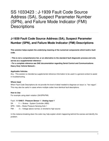
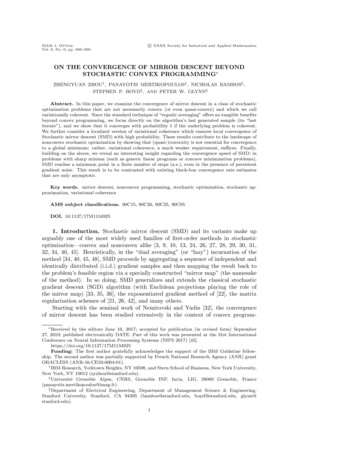
Safety First #24 July 2017The FMS assumes the use of managed speed and accounts for all the speedsand altitude constraints coded on the FMS flight plan. Refer to (fig.10).During the descent, approach and landing the managed speed is equal to either:- ECON DES speed or the descent speed manually entered in the PERF DESpage of the FMS, or- The speed constraint, or- The manoeuvring speed of the current aircraft configuration, or- VAPP.(fig.10)Top ofDescent(T/D)Typical managed descent profile(without Continuous Descent Approach(CDA) function)Cruise Altitude“AT or BELOW”Altitude“AT”Constraint FL100DecelPointDTargetSpeedActualspeedECON DESMACHFinalDescentPointFinal Capture AltitudeL/GDownECON DES SPDVAPP at 1000ft AGLUP1000ft250DOWNSVAPPFFLAPS123FLAPS FULL013
PROCEDURESControl your Speed During Descent, Approach and LandingIMPACT OF THE WIND ON THE DESCENT PATHThe descent path computed by the FMS uses theforecasted wind entered in the DESCENT WIND page.However, in flight, actual conditions may vary fromthe predicted ones. As a consequence, the differencebetween the predicted descent wind and the actualwind (Δwind) affects the aircraft’s behavior. If the speedtarget is maintained (as in OP DES mode), the aircrafttends to leave the FMS computed idle path (fig.11).FMS WindActual Wind windFMS wind(fig.11)Impact of the wind on the aircraft pathComputed PathFMS WindActual Wind
Safety First #24 July 2017Managed Descent (DES)The managed descent mode guides the aircraft along the FMS computedvertical flight path. The DES mode is preferred when conditions permit sinceit ensures the management of altitude constraints and reduces the operatingcost when flying at ECON DES speed.The DES mode is only available when the aircraft flies on the FMS lateral flightplan, i.e. when the aircraft uses the NAV horizontal guidance mode.(fig.12)Speed range principle during the idlesegment of a managed descent. wind (FMS wind vs Actual wind)Less Headwindor More TailwindMore Headwindor less TailwindInterceptPoint(on ND)PFDSpeedScaleOn idle segmentIn DES mode with managed speed the elevators adjust the pitch to enablethe aircraft to stay on the computed path and the A/THR commands idle thrust.The AFS allows the aircraft speed to vary in a range of /- 20 knots aroundthe managed speed target ( 5 kt or -20 kt in the case of a speed constraint),limited to VMAX -5kt to stay on path:- If the speed decreases down to its lower limit, the A/THR will increase the thrust- If the speed reaches its upper limit, the aircraft will leave the path to maintainthe upper limit speed.015
PROCEDURESControl your Speed During Descent, Approach and LandingOn geometric segmentOn the geometric segment, the A/THR adapts thrust to maintain the managedspeed target.Use of speedbrakes in DES modeThe use of speedbrakes in DES mode must be limited to the situation where thereis either a strong tailwind or much less tailwind than expected, and the aircraftdiverges from the profile. The flight crew should increase drag by extending thespeed brakes (fig.12).As a visual clue the ND displays the intercept point at which the aircraft will reachthe profile with half speed brakes extended. If the flight crew does not extend thespeed brakes the interception point will continuously move forward along the flightplan. If the interception point gets closer to an altitude constraint, a ‘‘MORE DRAG’’or EXTEND SPD BRK’’ message is displayed on the FMA and on the MCDUscratchpad/MFD.Note: The speed range does not apply below FL 100 for A350 and A330 equippedwith HONEYWELL P5 FMS 2 release 2. In this case, the aircraft stays on the pathand the flight crew must monitor the speed and use speedbrakes when appropriate.In OP DESmode, the A/THRcommands idle thrustand the elevatorsadjust the pitch tomaintain the targetspeed.Selected Descent (OP DES and V/S)In OP DES mode, the AFS commands idle thrust and the elevators adjust the pitchto maintain the target speed (managed or selected).(fig.13)Adjustment of the selected speed to modifythe descent path.The OP DES mode can be used to increase or reduce the descent slope. In OPDES, the flight crew adjusts the target speed to modify the descent path (fig.13).Selected Speed Increase Descent Slope Increase
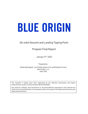
Safety First #24 July 2017The flight crew can use the V/S mode during descent to get accurate guidanceto recover the intended flight path by adjusting the V/S using the V/S selector.In V/S mode, the AFS adjusts pitch and thrust to maintain the selected verticalspeed and the target speed.Tools for Energy Management during DescentV/DEV IndicationWhen in NAV lateral mode, the flight crew uses the ‘‘yoyo’’ indication to estimateits position relative to the FMS computed path. The Vertical deviation (V/DEV) valueis provided on the FMS PROG page (A320/A330/A340) (fig.14) or PERF DESpage (A380/A350).(fig.14)example of V/DEV indication on the PFD andon the FMS PROG page (A320)V/DEV or "yoyo"Energy CircleWhen in HDG or TRK lateral mode, the ND displays the energy circle, and whenthe aircraft is within 180 NM of its destination. It provides a visual cue of theminimum required distance to land, i.e. the distance required to descend in astraight line from the current aircraft position at its current speed down to thealtitude of the destination airport at approach speed. The descent profile used tocompute the distance takes into account speed limits, the wind, a decelerationlevel off segment and a 3 final approach segment (fig.15). In other words, ifthe destination airport is inside the energy circle, the flight crew needs to losesome energy by extending the speed brakes and/or modifying the aircraft’strajectory, and/or increasing speed during descent.In HDG orTRK lateral mode,the Energy Circleprovides a visualcue of the minimumrequired distance toland.017
PROCEDURESControl your Speed During Descent, Approach and Landing(fig.15)Energy Circle Computation PrincipleCurrentAircraft AltitudeDestinationAirport AltitudeDescent fromCurrent Altitude3 FinalDecelerationApproachLevel-offSlopeRequired Distance to LandLevel-off ArrowAnother useful tool to use during descent is the level-off arrow provided by the FMS.It provides an indication to the flight crew of where the aircraft will reach the altitudeselected on the FCU (fig.16). A blending of actual wind conditions and the valuesfor winds entered in the FMS are used to improve the accuracy of the computation.If in selected descent, the flight crew can adjust the speed of the aircraft to adaptthe descent path or V/S to the situation.(fig.16)Level-off Arrow Computation PrincipleCurrentAircraft AltitudeFCU AltitudeRequired distance to reach FCU Altitude
Safety First #24 July 2017Overspeed Avoidance during DescentManual Flight at Crossover AltitudeWhen in descent close to MMO, if in manual flight (AP off), the risk of exceedanceof the VMO at the crossover altitude is high. In this situation, the flight crew shouldknow its crossover altitude and anticipate the switch to speed by reducingthe aircraft pitch on approaching the crossover altitude.Impact of Wind DirectionFlight crews should pay particular attention monitoring their speed in descentclose to VMO/MMO and when flying close to the wind direction (fig.17). The impactof a wind gradient can be significant and bring the aircraft beyond VMO/MMO.(fig.17)Impact of wind directionWindWindHeadwindComponentFlying close to the wind direction Strong impact of potentialwind gradients on aircraft speedHeadwindComponentFlying far from the wind direction Limited impact of potentialwind gradients on aircraft speed019
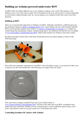
PROCEDURESControl your Speed During Descent, Approach and LandingMANAGING SPEED DURINGAPPROACH AND LANDINGInitial Approach(fig.18)Example of decelerated approachWhen reaching the Initial Approach Fix (IAF) the flight crew should have adefined approach strategy based on the selected type of approach: a choiceof the guidance mode that will be used and the associated approach technique(decelerated approach or early stabilized approach). The flight crew is thenready to start the key phase of the approach in terms of speed management:the Intermediate Approach phase.DECELERATED APPROACH (WITHOUT CDA FUNCTION)The decelerated approach is the default strategy usedby the FMS to compute the descent and approach path.It is the recommended strategy for approaches usingmanaged vertical guidance: ILS, GLS, SLS, MLS, FLSand FINAL APP.In a decelerated approach, the aircraft is deceleratingduring its final approach segment to be stabilized at VAPPat 1000ft above the airport elevation. In mostcases, it reaches the Final Descent Point(FDP) in CONF1 at S speed. However,DecelPointDin some cases, when the deceleration capabilities are low(e.g. heavy aircraft, a high elevation airport or tailwind),or for particular approaches with a deceleration segmentlocated at low height, the flight crew should select CONF2 before the FDP. The FCOM recommends to selectCONF 2 before the FDP when the interception of the finalapproach segment is below 2000ft AGL (A320) or 2500ftAGL (A330/A340, A350 and A380). In this case, for ILS,MLS or GLS approaches, or when using FLS guidance, itis good practice to select FLAPS 2 when one dot belowthe glideslope on the PFD deviation scale.FinalDescentPointTargetSpeedActualspeedVAPP at 1000ft AGLL/GDownUP1000ft250DOWNSVAPPFFLAPS123FLAPS FULL
Safety First #24 July 2017Intermediate ApproachThe Intermediate Approach phase starts at the deceleration point or earlier,if the flight crew activates manually the approach phase of the FMS.The aircraft reduces speed from its last descent speed, generally 250kt,corresponding to the speed limit below FL100. The aircraft slows down to greendot speed and then slows further to the manoeuvring speed for the various Slats/Flaps configurations. It finally ends up at VAPP at or before the stabilization point(decelerated approach) or at or before the Final Descent Point (early stabilizedapproach) depending on the approach strategy.Airbus recommends using A/THR in managed speed to reduce crew workload. Ifthe flight crew needs to use selected speed, they should revert to managed speedwhen out of the ATC speed constraint because it will ease the deceleration handling.(fig.19)Typical early stabilized approachEARLY STABILIZED APPROACH (WITHOUT CDA FUNCTION)The early stabilized approach is the recommendedtechnique for approach using selected FPA verticalguidance. When the interception height of the finaldescent segment is low (below 2000ft for A320 or2500ft for A330, A340, A350 and A380), it may also beused as an alternative to the decelerated approach toreduce flight crew workload. Early stabilized approachcan also be used when the weather conditions make ittoo difficult to use the decelerated approach. During anearly stabilized approach, the aircraft reaches the FDP atVAPP and in its landing configuration. To do so, the flightcrew enters a speed constraint at the FDP in the FMSflight plan to enable the FMS to compute an associateddeceleration point.FinalDescentPointDecelPointDVAPP at the FinalDescent LAPS123FLAPS FULL021
PROCEDURESControl your Speed During Descent, Approach and LandingThe deceleration rate of the aircraft varies with its weight. A heavy aircraft willnot decelerate as quickly as a lighter aircraft.Whatever the Approach technique chosen by the flight crew (decelerated orearly-stabilized approach), respecting stabilization criteria is key for a successfullanding. Refer to the Flight Crew Operating Manual FCOM/PRO-NOR-SOP-18-AStabilization Criteria.(fig.20)Typical CDA approachCONTINUOUS DESCENT APPROACH (CDA) FUNCTIONThe CDA function removes the deceleration level-offsegment for fuel economy and noise reduction purposes.The function displays pseudo waypoints on the ND toindicate where to extend the flaps at the latest to reachthe stabilization point (VAPP at 1000ft AGL for deceleratedDecelPointDapproaches and Vapp at the FDP for early stabilizedapproached). CDA is basic on A350 aircraft and will beavailable as an option on A320 and A330 aircraft familieson aircraft equipped with Release2 FMS standards fromHoneywell.FLAPS 2FLAPS 1Pseudo WaypointPseudo Waypoint12FinalDescentPointNo level-offDeceleration segmentTargetSpeedActualspeedVAPP at 1000ft AGLL/GDownUP1000ft250DOWNSVAPPFFLAPS123FLAPS FULLBESTPRACTICEIf needed and below VLO/VLE, early extension of the landing gear can help the aircraft to decelerate. The additional drag ofthe landing gear has a strong effect on the aircraft deceleration rate.
Safety First #24 July 2017Final approach and landingSpeed Monitoring during approach and landingWhen close to the ground, the wind can change, especially when in gusty conditions,and have a direct impact on the aircraft speed. As a consequence, monitoringof airspeed is crucial during final approach and landing to avoid:- Runway undershoot, hard landing or tail strike if the aircraft speed becomestoo low, or- Runway overrun if the speed becomes too high.If gusty conditions are expected at the destination airport, the flight crew can addan appropriate margin to the VAPP and manually enter the new VAPP in the FMSPERF APPR page.Airbus recommends the use of autothrust during final approach to reduce crewworkload and benefit from the Ground Speed Mini function (GS mini).Monitoring ofairspeed is crucialduring final approachand landing.023
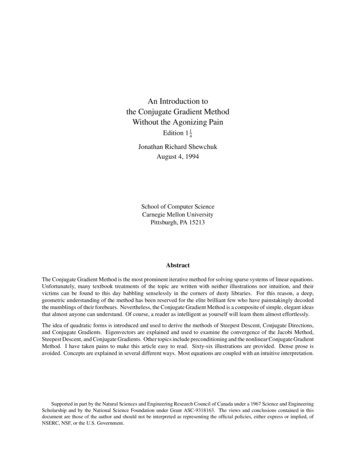
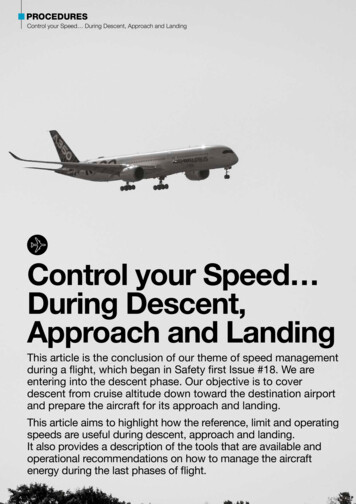
PROCEDURESControl your Speed During Descent, Approach and LandingWHAT IS THE GROUND SPEED MINI FUNCTION?Significant headwind changes can be caused by theboundary layer effect when the aircraft is getting closer to theground. Ground speed mini function ensures that the aircraftspeed remains at least at VAPP if a stronger than expectedheadwind were to suddenly drop to the tower wind value orbelow. The GS mini function is only available when the flightcrew uses the managed SPEED mode.- The approach speed (VAPP computed by the AFS ormanually entered in the FMS),- The tower headwind component from the tower wind valueentered by the flight crew in the PERF APPR page of theFMS, and- The current wind measured by the ADIRS.As a consequence, the flight crew must ensure that the towerheadwind value has been correctly entered in the FMS, evenif it does not increase the VAPP (i.e. headwind 15kts).The AFS constantly computes and displays a target IndicatedAirspeed (IAS) using:(fig.21)Ground speed mini functionk x HeadwindMax(1/3 TowerHeadwind; 5kt)VLSVAPPTargetIAS VAPPMax(1/3 TowerHeadwind; 5kt)VLSVAPPTargetIAS VAPP kx HeadwindCurrent Headwind Tower HeadwindCurrent Headwind Tower HeadwindTarget IAS VAPPTarget IAS VAPP k HeadwindAircraft typeA320ceoA320neoA330/A340Above 400ftk10.331ReducingA330/A340fromBelow 400ft 1 to 0.33in 25sA3500.33A3800.33With Headwind Current Headwind - Tower HeadwindWhy is there a different ‘k’ factor for ground speed mini depending on the aircraft model?The factor of 1 used on A320ceo aircraft could not beused for the other aircraft models due to differences oftheir deceleration capability. The A320ceo has a strongerdeceleration capability when compared to A320neo,A330/A340 family aircraft, A350 and A380 aircraft.In the case of a strong ground effect, a lower decelerationcapability may lead to an excessive speed at flare. Forexample, a 20kt headwind at 200ft that reduces to 5kton ground (corresponding to the 5kt tower headwindinserted in FMS PERF APPR page), a factor of 1 requiresa deceleration of 15kt to reach VAPP. With a k value of0.33, the aircraft only needs to decelerate by 5kt tocompensate its lower deceleration capability. It reducesthe risk of excessive speed at flare. The drawback isthat there is a slight increase in thrust variations ingusty conditions, since the speed increment will not besufficient to counteract the IAS increase due to a gust.The best overall compromise was demonstrated to bea 0.33 factor.
Safety First #24 July 2017Manual LandingIn Normal or alternate law, the flight controls maintain the aircraft load factor demand(flight mode), if there is a wind change, the aircraft will maintain its path causing thespeed to increase or decrease. This cannot be perceived by a pilot while lookingoutside, as the trajectory will not change (the aiming point will not move). Therefore,with autothrust disengaged, the flight crew must carefully monitor the speed as todetect any speed change. The role of the Pilot monitoring (PM) is key in this situation,especially when close to the ground.Stabilisation criteriaFlight crewsmust respectthe stabilisationcriteria providedin the FCOMStandard OperatingProcedures.Flight crews must respect the stabilisation criteria provided in the FCOM StandardOperating Procedures (SOPs). These criteria ensure a safe approach and landing.The aircraft must be at approach speed with stabilized thrust at the stabilisationheight (1000 ft AGL in IMC, 500 ft in VMC or according to airline’s policy) If it isnot the case, the PM should make a callout and a go around must be initiatedif the flight crew assesses that the stabilisation can’t be obtained prior landing.CONTRIBUTORS:Philippe CASTAIGNSExperimental Test PilotLorraine DE-BAUDUSFlight Operations Standards& Safety managementThe aircraft can be in either an over energy or low-energy situation atlanding if the crew does not manage the aircraft’s speed correctly from topof decent, through approach and down to the flare. The consequencesupon landing are increased risk of runway excursion, tail strike, hardlanding or runway undershoot.Whatever the level of automation chosen during descent, approachand landing, the flight crew should be aware of its capabilities, take fulladvantage of the tools available on airbus aircraft and apply the proceduresand techniques provided in the FCOM/QRH and FCTM.025
Energy management, and as a consequence speed management, is critical during descent, approach and landing phases. An aircraft . FE of the next Slats/Flaps configuration. Aircraft A320 A330/A340* A340-500/600 A350/A380 V FE PFD display based on: Slats/Flaps lever position Actual Slats/Flaps position For retraction: Actual Slats/Flaps