Transcription
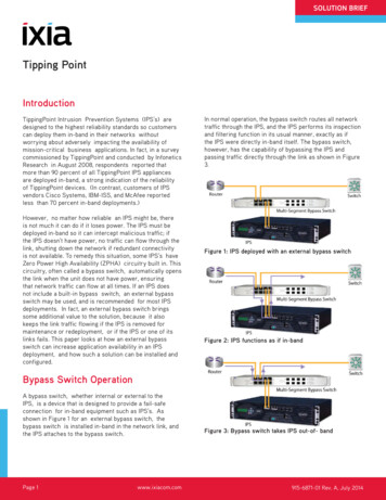
SOLUTION BRIEFTipping PointIntroductionTippingPoint Intrusion Prevention Systems (IPS’s) aredesigned to the highest reliability standards so customerscan deploy them in-band in their networks withoutworrying about adversely impacting the availability ofmission-critical business applications. In fact, in a surveycommissioned by TippingPoint and conducted by InfoneticsResearch in August 2008, respondents reported thatmore than 90 percent of all TippingPoint IPS appliancesare deployed in-band, a strong indication of the reliabilityof TippingPoint devices. (In contrast, customers of IPSvendors Cisco Systems, IBM-ISS, and McAfee reportedless than 70 percent in-band deployments.)However, no matter how reliable an IPS might be, thereis not much it can do if it loses power. The IPS must bedeployed in-band so it can intercept malicious traffic; ifthe IPS doesn’t have power, no traffic can flow through thelink, shutting down the network if redundant connectivityis not available. To remedy this situation, some IPS’s haveZero Power High Availability (ZPHA) circuitry built in. Thiscircuitry, often called a bypass switch, automatically opensthe link when the unit does not have power, ensuringthat network traffic can flow at all times. If an IPS doesnot include a built-in bypass switch, an external bypassswitch may be used, and is recommended for most IPSdeployments. In fact, an external bypass switch bringssome additional value to the solution, because it alsokeeps the link traffic flowing if the IPS is removed formaintenance or redeployment, or if the IPS or one of itslinks fails. This paper looks at how an external bypassswitch can increase application availability in an IPSdeployment, and how such a solution can be installed andconfigured.In normal operation, the bypass switch routes all networktraffic through the IPS, and the IPS performs its inspectionand filtering function in its usual manner, exactly as ifthe IPS were directly in-band itself. The bypass switch,however, has the capability of bypassing the IPS andpassing traffic directly through the link as shown in Figure3.Figure 1: IPS deployed with an external bypass switchFigure 2: IPS functions as if in-bandBypass Switch OperationA bypass switch, whether internal or external to theIPS, is a device that is designed to provide a fail-safeconnection for in-band equipment such as IPS’s. Asshown in Figure 1 for an external bypass switch, thebypass switch is installed in-band in the network link, andthe IPS attaches to the bypass switch.Page 1www.ixiacom.comFigure 3: Bypass switch takes IPS out-of- band915-6871-01 Rev. A, July 2014
SOLUTION BRIEFA Real-World ExampleFigure 4: TippingPoint 5000E IPS paired with a Net OpticsMulti-Segment Bypass SwitchOne scenario in which the bypass switch will take the IPSout-of-band is if the IPS loses power, and therefore cannotprocess network traffic. For this reason, an external bypassswitch is recommended if the IPS is not equipped withone internally. In addition, when an IPS is paired with anexternal bypass switch, the IPS can be removed from thelink at any time; the bypass switch senses the absence ofthe IPS and instantly opens the network link to traffic flow.While the benefits of a bypass switch are evident, you maywonder whether you are simply replacing one risk withanother, because the bypass switch is subject to failure aswell. However, having a bypass switch in-band instead ofthe IPS itself has several advantages: The bypass switch, whether internal or external,ensures that link traffic continues to flow when nopower is available A bypass switch is a much simpler device than an IPS,so it is much less likely to fail A bypass switch passes 100 percent of the networktraffic, no matter how busy the link is; it never runs outof bandwidth and therefore never needs to be upgraded External bypass switches are often installed incritical links as permanent parts of the networkinfrastructure, so they never need to be removed fromlinks, even when the security strategy or the networkconfiguration changesA perfect companion bypass switch for TippingPoint5000E and 2400E IPS’s (which do not have internal bypassswitches) is a Net Optics Four- Station Multi-SegmentBypass Switch. Both devices support four network links,and both can be ordered in configurations with all copper,all fiber, or half copper and half fiber ports. Both SX andLX fiber are supported. The two devices can be paired asshown in Figure 4.This configuration protects four critical network segmentsand occupies only 3U of rack space, 2U for the IPS and 1Ufor the Bypass Switch.For example, a TippingPoint 2400E appliance is often agood choice to protect four 1-gigabit-per-second networklinks if the links are less than 50 percent utilized. However,suppose that over time network usage grows and the2-gigabit-per-second aggregate throughput capability of the2400E becomes a bottleneck on the network. A properlymanaged network may function well at utilizations of 80percent or more, so it may be possible to continue to meetservice- level agreements without upgrading the network—except that the IPS no longer has the bandwidth to handleall of the traffic. The most cost-effective solution maybe to upgrade from a 2400E to a 5000E, which supports5 gigabits per second of throughput. If the 2400E wasdeployed with a Multi-Station Bypass Switch, upgrading isa cinch. The cables are simply unplugged from the 2400E(the Bypass Switch automatically and transparently keepsthe network traffic flowing), the 5000E is swapped forthe 2400E in the rack, and the cables are plugged intothe 5000E. As soon as the 5000E is powered up and iscapable of passing traffic, the Bypass Switch automaticallyswitches it in-band and the network is protected. There isno need to wait for a maintenance window or worry aboutimpacting application traffic.Failover OperationLet’s take closer look at how an external bypass switchkeeps the traffic flowing.Ixia Worldwide Headquarters26601 Agoura Rd.Calabasas, CA 91302(Toll Free North America)1.877.367.4942(Outside North America) 1.818.871.1800(Fax) 818.871.1805Ixia European HeadquartersIxia Technologies Europe LtdClarion House, Norreys DriveMaidenhead SL6 4FLUnited KingdomSales 44 1628 408750(Fax) 44 1628 639916Ixia Asia Pacific Headquarters21 Serangoon North Avenue 5#04-01Singapore 554864Sales 65.6332.0125Fax 65.6332.0127www.ixiacom.comPage 2www.ixiacom.com915-6871-01 Rev. A, July 2014
SOLUTION BRIEFThe Net Optics Multi-Station Bypass Switch has threemechanisms for triggering a bypass, that is, for takingthe IPS out-of-band. The mechanisms are power lossdetection, link loss detection, and Heartbeat packet.Each of these mechanisms is described in the followingsections.Power Loss DetectionThe Multi-Station Bypass Switch has dual redundant powersupplies and ZPHA circuitry that detects loss of power.When the dual redundant power supplies are connectedto independent power sources, total loss of power shouldbe rare, because either power supply alone can power theunit. However, when both power sources fail, the ZPHAcircuitry ensures that the Bypass Switch creates an openchannel that enables network traffic to keep flowing whilethe Bypass Switch has no power. When power is restored,the Bypass Switch automatically comes back on-line and, ifthe IPS is detected to be present and functioning, restoresthe flow of network traffic through the IPS.The Tolly Group conducted independent tests on a NetOptics Bypass Switch (10/100/1000 copper model) in April2008. They reported the time from a power fail conditionon the Bypass Switch to when the network connectionwas re-established and traffic resumed flowing to be 0.82seconds.Link Loss DetectionThe Multi-Station Bypass Switch monitors the linksbetween its ports and the IPS. If a link is dropped, theswitch immediately enters “bypass on” mode taking theIPS out-of- band and enabling traffic to flow unimpededthrough the link. The Tolly Group induced this condition byunplugging one of the cables that connected the BypassSwitch to the IPS, and measured a failover time of 0.76seconds. This test reflects the real-world scenario whereinthe IPS is removed from the network for any reason, anddemonstrates that application traffic keeps flowing whenthe IPS is simply unplugged and removed.powered and the links to the IPS remain up. An example ofthis scenario is when the traffic exceeds the capacity of theIPS, so that latencies through the IPSstart to increase. To detect this type of condition, theBypass Switch periodically sends small Heartbeat packetsthrough the IPS to confirm that it is operational. TheHeartbeat packets are sent out one port to the IPS, and theBypass Switch expects to see the packet returned on theother port within a certain amount of time. If the packetdoes not arrive within the expected time window, theBypass Switch assumes the IPS is having a problem andtakes it out-of-band. (The Heartbeat packet is received bythe Bypass Switch but it is never passed to the externalnetwork link.)The Tolly Group tested the Heartbeat packet mechanismby programming the IPS to filter the Heartbeat packet,so it would not be returned to the Bypass Switch. Theydetermined that in this scenario, the failover time was lessthan one millisecond.Device ManagementTippingPoint IPS’s are quick and easy to deploy. Fortytwo percent of TippingPoint customers in the previouslyreferenced Infonetics Research survey reported installingthe IPS in less than 30 minutes, and 76 percent in less thantwo hours. (For comparison, only 17 percent of IBM- ISScustomers reported a two-hour or less set-up time.) Inaddition, two- thirds of TippingPoint customers said thatonly a light effort was required to configure the IPS filters,and only three percent said it took significant effort.Some customers may wish to adjust some of the BypassSwitch’s configurable features for their application.Bypass Switch configuration is easily accomplishedwith a command-line interface (CLI) operating over anRS232 serial port. The Multi-Segment Bypass Switchhas a separate RS232 port for each of the four segments,because the Bypass Switches that control the segmentsare completely independent from each other for addedreliability and security.A third method of triggering a “bypass on” condition isrequired for cases when the Bypass Switch remainsIxia Worldwide Headquarters26601 Agoura Rd.Calabasas, CA 91302(Toll Free North America)1.877.367.4942(Outside North America) 1.818.871.1800(Fax) 818.871.1805Ixia European HeadquartersIxia Technologies Europe LtdClarion House, Norreys DriveMaidenhead SL6 4FLUnited KingdomSales 44 1628 408750(Fax) 44 1628 639916Ixia Asia Pacific Headquarters21 Serangoon North Avenue 5#04-01Singapore 554864Sales 65.6332.0125Fax 65.6332.0127www.ixiacom.comPage 3www.ixiacom.com915-6871-01 Rev. A, July 2014
SOLUTION BRIEFThe configurable features of the Bypass Switch include thefollowing: Link Fault Detect (LFD) – disables the remaining sideof a full-duplex link when one side of the link fails,ensuring that the network can failover to an alternatepath (if available) in a timely manner; the defaultsetting for LFD is On Bypass Detect – when in “bypass on” mode, BypassDetect cycles the monitor ports through five secondsoff followed by ten seconds on; the resultingalternating link status can trigger the attached IPS tosend an alarm to a management system; Bypass Detectactivates when the Heartbeat packet is not returnedfrom the IPS device; the default setting of BypassDetect is Off Fail Mode – When the Fail Mode setting is “open,” the“bypass on” state of the switch is to open the networklink and permit traffic to flow, as discussed previously;when the setting is “closed,” the “bypass on” statecloses the network link so no traffic flows, enablingfailover network settings to take effect; the defaultsetting for Fail Mode is OpenFigure 6: Bypass triggered by loss of link between the IPSand the Bypass SwitchFigure 7: Operation of the Bypass Switch Heartbeat packetFigure 8: Net Optics Multi-Segment Bypass Switch FrontPanelFigure 5: Bypass triggered by loss of power to the BypassSwitchIn addition, 10/100/1000 copper-media ports can beconfigured to a fixed speed of 10, 100, or 1,000 megabitsper second, and to full or half duplex mode. The defaultsettings are automatic negotiation of link speed, and fullduplex mode.The Bypass Switch’s Heartbeat packet is also configurable.Besides the actual packet content, the interval betweenHeartbeat packets and the retry count may be configured.The default interval between Heartbeat packets is onesecond; it can be set from 1 to 254 seconds. The defaultretry count is three, meaning that the Bypass Switch takesthe IPS out-of-band when three Heartbeat packets havefailed to be returned. The retry count can be set from 1 to254. The default Heartbeat packet configuration works wellwith Tipping Point 5000E and 2400E IPS’s.Ixia Worldwide Headquarters26601 Agoura Rd.Calabasas, CA 91302(Toll Free North America)1.877.367.4942(Outside North America) 1.818.871.1800(Fax) 818.871.1805Ixia European HeadquartersIxia Technologies Europe LtdClarion House, Norreys DriveMaidenhead SL6 4FLUnited KingdomSales 44 1628 408750(Fax) 44 1628 639916Ixia Asia Pacific Headquarters21 Serangoon North Avenue 5#04-01Singapore 554864Sales 65.6332.0125Fax 65.6332.0127www.ixiacom.comPage 4www.ixiacom.com915-6871-01 Rev. A, July 2014
SOLUTION BRIEFThe status of the links and the bypass state of the MultiSegment Bypass Switch can be viewed through the CLI. Itis also shown with LEDs on the device’s front panel. Eachof the four independent switches has a pair of LEDs thatshow whether the state is “bypass on” (IPS out-of-band) or“bypass off” (IPS in-band). In addition, each port has twoLEDs displaying the link state: a Link LED that indicateswhether the link is present or not, and an Activity LEDthat flashes when data is passing through the port. For10/100/1000 ports, the color of the Link LED also indicatesthe link speed, amber for 10 megabits per second, yellowfor 100 megabits per second, and green for 1,000 megabitsper second, as clearly explained with a key silkscreened onthe panel. Finally, each of the four switches has a pair ofLEDs indicating whether the two redundant power suppliesare active or off.If remote management of the Multi- Segment BypassSwitch is desired, an inexpensive four-port RS232 terminalserver can be obtained from any of a number of sources toenable access to the management ports over a network orover the Internet.Ixia Worldwide Headquarters26601 Agoura Rd.Calabasas, CA 91302(Toll Free North America)1.877.367.4942(Outside North America) 1.818.871.1800(Fax) 818.871.1805ConclusionTippingPoint IPS’s are designed for maximum reliability,with features such redundant configurability, link downsynchronization, and hardware watchdogs. However,availability of business-critical applications can still beaffected when an IPS loses power, of if it needs to beremoved from a network link or upgraded to a new model.An external ZPHA or bypass switch ensures a higherlevel of application availability by guaranteeing that linktraffic keeps flowing in all of these scenarios. A NetOptics Four- Station Multi-Segment Bypass Switch is anideal companion for TippingPoint 5000E and 2400E IPS’sbecause together they can protect four critical networklinks with as much as 5 gigabits per second of total traffic,with high reliability and the flexibility of being able toremove or upgrade the IPS’s at any time, without riskingthe availability of critical business applications.Ixia European HeadquartersIxia Technologies Europe LtdClarion House, Norreys DriveMaidenhead SL6 4FLUnited KingdomSales 44 1628 408750(Fax) 44 1628 639916Ixia Asia Pacific Headquarters21 Serangoon North Avenue 5#04-01Singapore 554864Sales 65.6332.0125Fax 65.6332.0127www.ixiacom.comPage 5www.ixiacom.com915-6871-01 Rev. A, July 2014
Tipping Point In normal operation, the bypass switch routes all network traffic through the IPS, and the IPS performs its inspection and filtering function in its usual manner, exactly as if the IPS were directly in-band itself. The bypass switch, however, has the capability of bypassing the IPS and