Transcription
Aircraft DesignLecture 9:Stability and ControlG. DimitriadisIntroduction to Aircraft Design
Stability and ControlH Aircraft stability deals with the ability tokeep an aircraft in the air in the chosenflight attitude.H Aircraft control deals with the ability tochange the flight direction and attitudeof an aircraft.H Both these issues must be investigatedduring the preliminary design process.Introduction to Aircraft Design
Design criteria?H Stability and control are not design criteriaH In other words, civil aircraft are notdesigned specifically for stability andcontrolH They are designed for performance.H Once a preliminary design that meets theperformance criteria is created, then itsstability is assessed and its control isdesigned.Introduction to Aircraft Design
Flight MechanicsH Stability and control are collectivelyreferred to as flight mechanicsH The study of the mechanics and dynamicsof flight is the means by which :– We can design an airplane to accomplishefficiently a specific task– We can make the task of the pilot easier byensuring good handling qualities– We can avoid unwanted or unexpectedphenomena that can be encountered in flightIntroduction to Aircraft Design
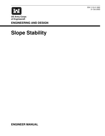
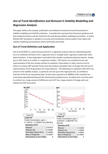
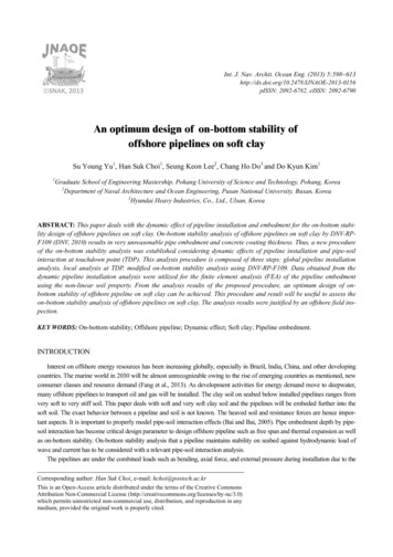
Aircraft descriptionPilotFlight ControlSystemAirplaneResponseTaskThe pilot has direct control only of the Flight ControlSystem. However, he can tailor his inputs to the FCS byobserving the airplane’s response while always keeping aneye on the task at hand.Introduction to Aircraft Design
Control SurfacesH Aircraft control is accomplished throughcontrol surfaces and power––––AileronsElevatorsRudderThrottleH Control deflections were first developed bythe Wright brothers from watching birdsIntroduction to Aircraft Design
Modern control surfacesRudderElevatorIntroduction to Aircraft DesignAileronRudderon(rudder aileron)Elevon(elevator aileron)
Other devicesFlapsAirbreakSpoilersHCombinations of control surfaces and other devices: flaperons,spoilerons, decelerons (aileron and airbrake)HVectoredthrustIntroduction to Aircraft Design
Aircraft degrees of freedomSix degrees offreedom:3 displacementsx: horizontal motiony: side motionvz: vertical motion3 rotationsx: rolly: pitchωcgxzyz: yawv: resultant linear velocity, cg: centre of gravityangular velocityω: resultantIntroductionto Aircraft Design
Airplane geometrycs b /2c /4cgc /4lTltIntroduction to Aircraft Designc(y)cy
Airplane references (1)H Standard meanchord(smc)ssc c ( y )dy / dy s sssH Mean aerodynamic chord (mac)c c ( y )dy / c ( y )dy2 sH Wing areaS bcH Aspect RatioAR b 2 /SIntroduction to Aircraft Design s
Airplane references (2)HHHHCentre of gravity (cg)Tailplane area (ST)Tail moment arm (lT)Tail volume ratio: A measure of theaerodynamic effectiveness of thetailplaneST lTVT ScIntroduction to Aircraft Design
Airplane references (3)cgc /4c /4lFlfH Fin moment arm (lF)SF lFH Fin volume ratio VF ScIntroduction to Aircraft Design
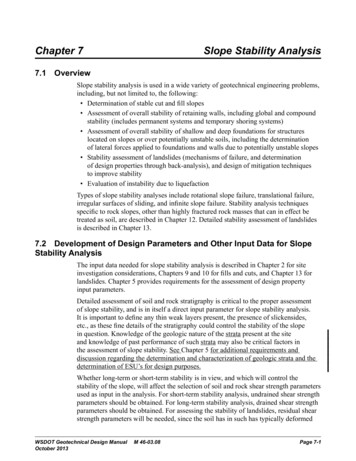
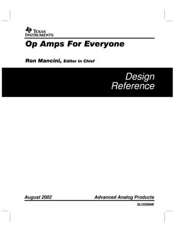
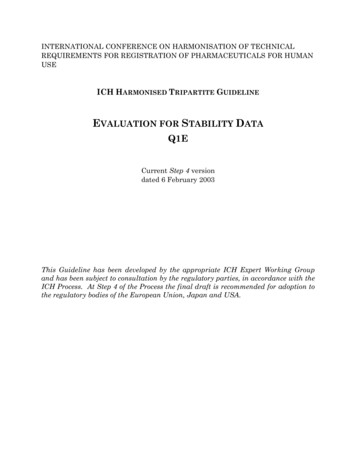
Aerodynamic Reference CentresH Centre of pressure (cp): The point at whichthe resultant aerodynamic force F acts. Thereis no aerodynamic moment around the cp.H Half-chord: The point at which theaerodynamic force due to camber, Fc, actsH Quarter-chord (or aerodynamic centre): Thepoint at which the aerodynamic force due toangle of attack, Fa, acts. The aerodynamicmoment around the quarter-chord, M0, isconstant with angle of attackIntroduction to Aircraft Design
By placing all ofthe lift and dragon theaerodynamiccentre we movethe lift and dragdue to camberfrom the halfchord to thequarter chord.This isbalanced by themoment M0Introduction to Aircraft DesignAirfoil with centresLcFcpFcDDcLaLCamber lineFaDaacV0LM0Dc /2chn cc /4
Static StabilityH Most aircraft (apart from high performancefighters) are statically stableH Static stability implies:– All the forces and moments around the aircraft’scg at a fixed flight condition and attitude arebalanced– After any small perturbation in flight attitude theaircraft returns to its equilibrium positionH The equilibrium position is usually called thetrim position and is adjusted using the trimtabsIntroduction to Aircraft Design
Pitching moment equationLTacLwcgMTM0lTmghch denotes the cgpositionch 0cIntroduction to Aircraft Design
Equilibrium equationsH Steady level flight is assumedH Thrust balances drag and they bothpass by the cgH Force equilibrium:Lw LT mg 0H Pitching moment around cg equilibrium:M M 0 Lw (h h0 )c LT lT MT 0(nose up moment is taken to be positive)Introduction to Aircraft Design
Stable or Unstable?H An equilibrium point can be stable,unstable or neutrally stableH A stable equilibrium point ischaracterized byM 0 anddM 0dαH A more general condition (takes intoaccount compressibility effects) isdMM 0 and 0dLIntroduction to Aircraft DesignordC mCm 0 and 0dCL
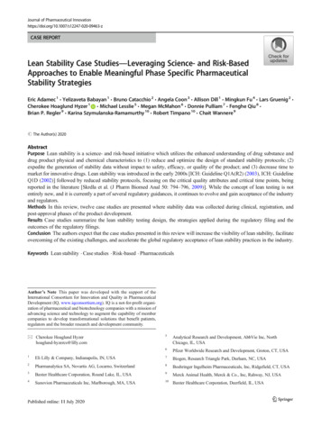
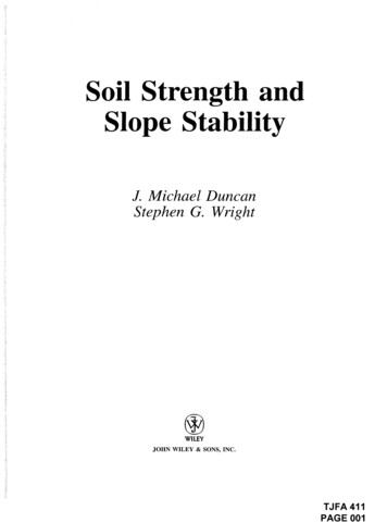
Degree of stabilityCm1234Trim point1: Very stable2: Stable3: Neutrally stable4: UnstableIntroduction to Aircraft Designα
Pitching moment stability (1)H The pitching moment equation can bewritten asCm Cm CL (h h0 ) CL VT 00H WhereCm M1ρV02 Sc2w, CL w TLw1ρV02 S2, CL T LT1ρV02 ST2H And the tailplane is assumed to besymmetric so that MT 0Introduction to Aircraft Design
Pitching moment stability (2)H For static stability dC m /dCL 0 or,approximately, dC m /dCL w 0H ThendCm /dCL (h h0 ) VT dCL /dCLwTwH Since M0 is a constant.H Unfortunately, the derivative of the taillift with respect to the wing lift isunknownIntroduction to Aircraft Design
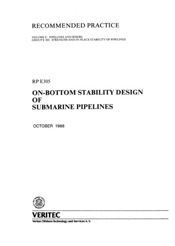
Wing-tail flow geometryH The downwash effect of the wing deflects thefree stream flow seen by the tailplane by anangle ε.H Total angle of attack of tail: αT α-ε ηTTailplaneηβηElevatorWingηTαεαTV0Trim tabH The total lift on the tailplane is given by:CLT α 0 a1α T a2η a3βηIntroduction to Aircraft DesignαV0
Pitching moment stability (3)H For small disturbances the downwashangle is a linear function of wingincidence α:dεε αdαH Wing lift is also a linear function of α:CL aα or α CL /awH So thatIntroduction to Aircraft DesignwCLw % dε (αT * ηT'1 a & dα )
Pitching moment stability (4)H The tail lift coefficient can then bewritten as a1 % dε (CL T CL w* a1ηT a2η a3βη'1 a & dα )H And the derivative of the pitchingmoment coefficient becomes% a % dε (dβ ηdηdCm1 (h h0 ) VT '' '1 a3* a2dCLwdCLwdCLw& a & dα )H since ηT is a constantIntroduction to Aircraft Design(**)
Controls fixed stabilityH Assume that the aircraft has reachedtrim position and the controls are lockedH What will happen if there is a smallperturbation to the aircraft’s position(due to a gust, say)?H The pitching moment equation becomesa1 % dε (dCm (h h0 ) VT '1 *dCLwa & dα )Introduction to Aircraft Design
Stability marginH Define the controls fixed stability margin asKn dCmdCLwH And the controls fixed neutral point asa1 % dε (K n hn h, so that hn h0 VT '1 *&adα )H A stable aircraft has positive stability margin.The more positive, the more stable.H If the cg position (h) is ahead of the neutralpoint (hn) the aircraft will by definition bestableH Too much stability can be a bad thing!Introduction to Aircraft Design
Stability marginH Certification authorities specify thatK n 0.05at all timesH Of course, the stability margin can change:– If fuel is used up– If payload is released:HHHHHBombsMissilesExternal fuel tanksParatroopersAnything else you can dump from a planeIntroduction to Aircraft Design
Controls Free StabilityH Pilots don’t want to hold the controlsthroughout the flight.H The trim tab can be adjusted such that, if theelevator is allowed to float freely, it will at anangle corresponding to the desired trimcondition.H This is sometimes called a hands-off trimcondition.H Therefore the pilot can take his hands off theelevator control and the aircraft will remain intrim.Introduction to Aircraft Design
Controls Free Stability MarginH This is an expression for η that can besubstituted into the pitching momentequation.H Differentiating the latter with respect to winglift coefficient givesa1 % dε (% a2b1 (dCm ( h h0 ) VT '1 *'1 *dCLwa & dα )& a1b2 )H Where b1, b2 and b3 define the elevator hingemoment coefficientC H b1α T b2η b3βηTailplaneElevator hinge HηIntroduction to Aircraft DesignβηElevatorTrim tabηTα αΤVε 0
Controls Free Neutral PointH Define the Controls Free StabilityMargin, K'n, such thatdCm hn! hK n! dC LwH The controls free neutral point is thena1 & dε )& a2b1 )hn" h0 VT (1 (1 a ' dα *' a1b2 *a2b1 & dε (1 or hn" hn VT'ab2dα )Introduction to Aircraft Design
DiscussionH As with the controls fixed stability margin, thecontrols free stability margin is positive whenthe aircraft is stable.H Similarly, the centre of gravity position mustbe ahead of the controls free neutral point ifthe aircraft is to be stable.H Usually, the constants of the elevator and tabare such that h'n hn.H An aircraft that is stable controls fixed willusually be also stable controls freeIntroduction to Aircraft Design
Summary of LongitudinalStabilityK n" cK nccg ach0chchn chn" ccIntroduction to Aircraft Design
Lateral stabilityH There are two types of lateral motion foran aircraft:– Roll– YawH The aircraft must be stable in both ofthese directions of motionIntroduction to Aircraft Design
Roll Stability MechanismH There is no active stabilizing mechanism forlateral stability (e.g. tail for longitudinalstability, rudder for yaw stability)H Wing dihedral, Γ, is the only stabilizingmechanismH The higher the dihedral angle, the morestable the aircraftH As usual, too much stability can be a badthingIntroduction to Aircraft Design
Roll MotionLLcosφLLsinφφ’mgSteady level flight: L mgv φymgWhen at a roll angle φ, the lift L is still equalzto mg.However, Lcosφ mg and there is a sideslip force Lsinφ.Therefore the aircraft is moving to the side and down, withspeed v.Introduction to Aircraft Design36
Sideslip angleH Using trigonometry it can be shown that,the angle φ’ between the sideslip vectorv and the horizontal is always φ/2.LcosφLLsinφφ’vφymgIntroduction to Aircraft Designz37
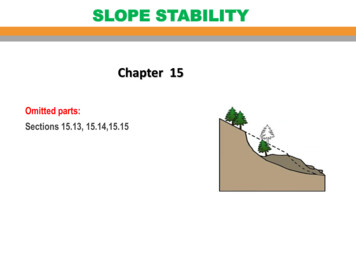
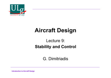
High-wing aircraftLCPCGThe mgsinφ componentcauses a restoringmoment around thecentre of pressuremgCP: centre of pressure(point of application oflift vector)CG: centre of gravityLCPCGmgcosφφmgsinφConclusion: high-wingaircraft are inherently stablein rollIntroduction to Aircraft Design
Low-wing aircraftLCGCPThe mgsinφ componentcauses a destabilisingmoment around thecentre of pressuremgLCGmgsinφCPConclusion: low-wingaircraft are inherentlyunstable in rollIntroduction to Aircraft Designmgcosφφ
DihedralHigh-wingaircraft:Dihedralreduces tyIntroduction to Aircraft DesignΓΓ
Restoring momentl leadingStabilising moment, R (Lt Ll ) yt trailingLty-RLl LtvIntroduction to Aircraft DesignΓφ’v’φ41
Roll stabilityH For a stable aircraft in roll, dCR/dφ 0.CRIntroduction to Aircraft Design42
Aircraft with negative dihedralF104 StarfighterC5 GalaxyIntroduction to Aircraft DesignAlpha JetAntonov 22543
Roll ControlH Roll control can be accomplished usingthe aileronsLess lift, less drag‘Adverse yaw’δ2The total aileronangle is given byδa (δ1 δ2)/2Introduction to Aircraft DesignMore lift, more dragδ144
Aileron adverse yawH Increasing the lift also increases thedrag and vice versa.H When deflecting ailerons, there is a netyawing moment in an opposite directionto the rolling moment.– When rolling left (in order to turn left), thereis a yawing moment to the right– This can make turning very difficult,especially for high aspect ratio wingsIntroduction to Aircraft Design45
Roll control by spoilersH Another way of performing roll control isby deforming a spoiler on the wingtowards which we want to turn. To turn‘Proverse yaw’left:The spoilerdecreases lift andincreases drag.Now the yawingmoment is in thesame direction asthe roll.Introduction to Aircraft Design46
Frise AileronsThe idea is to counteract the higher lift induced drag ofthe down wing with higher profile drag on the up wing.Frise ailerons areespecially designed tocreate very highprofile drag whendeflected upwards.When deflecteddownwards the profiledrag is kept low. Thus,they alleviate or, even,eliminate adverse yawIntroduction to Aircraft Design47
Differential Aileron DeflectionH The roll rate of the aircraft depends onthe mean aileron deflection angle. Theindividual deflections δ1 and δ2 do nothave to be equal.Differential deflectionmeans that the upaileron is deflected by alot while the down aileronis deflected by a little.Introduction to Aircraft Design48
Yaw StabilityVxcgVβxyyLFIn this case the flow is symmetric;In this case the vertical stabilizer (fin) is at aThere is no net moment around the z axis positive angle of attack. It produces aIntroduction to Aircraft Designstabilizing moment around the z axis
Fin MomentThe lift coefficient of the fin can beexpressed asCL c1α F c 2δ c1 ( β σ ) c 2δFσαF-βcglFVLFc /4NHRδIntroduction to Aircraft DesignWhere σ is the sidewashvelocity, a local windspeedcomponent induced by theeffect of the fuselage, wingand possibly propellers.SF lFCn CLF VF , where VF Sc
Yaw stabilityH The stability condition for yaw motion isthen dC&dσdδ ) 0, or, VF ( c1 c1 c2 0dβdβdβ *'nH Note that, in this case, it makes nosense to differentiate the yawingmoment by the lift since the two areindependent.H The sidewash factor, dσ/dβ, is verydifficult to estimateIntroduction to Aircraft Design
Sidewash factorH There are three main contributions tosidewash:– Fuselage: It acts as a lifting body when at a yawangle– Wing: The flow over the wing is asymmetric. Theresulting sidewash is more pronounced for lowaspect ratio sweptback wings.– Propeller: The flow behind the propeller is alsoyawed, causing additional asymmetry.H Sidewash factors can be estimated mostaccurately by carefully designed wind tunnelexperiments.Introduction to Aircraft Design
Yaw controlH During most flight conditions the yaw anglemust be zero - this minimizes dragH This is achieved through the deflection of therudder.H Rudder power: Rate of change of fin momentdCLwith rudder angle dCn VF c 2VFdδdδH This quantity must be large enough tomaintain zero yaw even at the most extremeflight conditions.FIntroduction to Aircraft Design
Take off and landing (1)H During cruise, aircraft tend to turn towardsthe wind in order to minimize their drag.Therefore, the objective is to achieve 0oyaw.H At take-off and landing this is not possible.The aircraft must remain aligned with therunway, even in the presence of a verystrong sidewind.H Therefore, the rudder must be able toprovide a moment that can keep theaircraft aligned with the runway.Introduction to Aircraft Design54
Take off and landing (2)βRelative wind, VRunway directionβRelative wind, VRunway directionyyLFUndeflected rudder: fin has a sizeable liftcausing a moment around the c.g.Introduction to Aircraft DesignLF 0Deflected rudder: fin creates 0 lift and 0moment around the c.g.55
Roll-Yaw couplingH Roll and yaw are always coupled.H There are several reasons for thecoupling:––––––Rolling produces sideslipAilerons cause adverse yawDihedral cases additional couplingWingtip vortices cause additional couplingSweepback causes additional couplingThe fin causes additional couplingIntroduction to Aircraft Design
Summary on Control surfacesH Elevators contribute to pitch stability andcontrol pitch angle.H Rudder contributes to yaw stability andcontrols yaw angle.H Ailerons do not contribute to stability.Furthermore, they control the roll rate, not theroll angle. There is no moment to balance theeffect of the ailerons: They provide a constantmoment that causes continuous roll rotation,whose rate also depends on the moment ofinertia of the aircraft.Introduction to Aircraft Design57
More control surfacesH Elevons contribute to stability and control ofboth pitch and roll. They are ailerons that canalso move up or down in unison, just likeelevators.H Flaperons contribute to stability and control ofboth pitch and roll. They are ailerons that canalso move downwards only, just like flaps.H Spoilerons contribute to stability and control ofboth pitch and roll. They are ailerons that canalso move upwards only, just like spoilers.Introduction to Aircraft Design58
Modes of vibration of aircraftH Stability must also be investigated in adynamic senseH Aircraft have several modes of vibration:– Longitudinal modes:H Short Period OscillationH Phugoid– Lateral modes:H Spiral modeH Roll subsidenceH Dutch rollIntroduction to Aircraft Design
Phugoid oscillationsH Phugoids are long period oscillations that occuronly in the longitudinal direction.H The angle of attack is constant; the aircraft climbsand descends in an oscillatory manner.H Phugoids are also very lightly damped.H Phugoid periods:– Microlight aircraft: 15-25s– Light aircraft: over 30s– Jet aircraft: minutesH Phugoids are neutralized by re-trimming theaircraft in the new flight condition.Introduction to Aircraft Design
Phugoid VideosIntroduction to Aircraft Design
Phugoid approximationH The Lanchester approximation states that thephugoid damping ratio and frequency are givenby:gCDg 2ζ pω p , ωp CLV0V0Introduction to Aircraft Design
More about PhugoidsH Phugoid periodincreases withairspeed. Phugoiddamping increaseswith airspeed.H Compressibility effectsH Period and dampingfor a Boeing 747 atseveral altitudes andMach numbersNhalf number of periods until theamplitude is halvedIntroduction to Aircraft Design
Short period oscillationsH Short period oscillations have a much higherfrequency than Phugoids.H They are driven by the angle of attack (infrench they are called oscillationsd’incidence).H Speed changes are negligibleH They occur after abrupt input changes.Slower input changes do not cause significantshort period oscillationsIntroduction to Aircraft Design
Short Period DependenciesH The period generallydecreases withairspeed. Thedamping can eitherdecrease or increaseH Compressibility effectsH Period and dampingfor a Boeing 747 atseveral altitudes andMach numbersIntroduction to Aircraft Design
Spiral modeH This mode is quite visible in the impulseresponse of the lateral equationsH It is the non-oscillatory mode with large timeconstantH It is mainly a yaw movement with a little rollH This mode can be stable or unstable. It isunstable quite often but that is not a problembecause of its large time constantH The typical half-life of a spiral mode is of theorder of a minute.H The spiral movement is usually stopped by acorrective control inputIntroduction to Aircraft Design
Spiral Mode VideoIntroduction to Aircraft Design
Roll subsidenceH An impulse aileron input will start the aircraftrolling.H In general, the aircraft will stop rolling withtime (i.e. the roll rate becomes zero aftersufficient time)H The aircraft will find itself at a roll angle whichdepends on how fast the roll rate tends tozero.H This phenomenon is called roll subsidence.Introduction to Aircraft Design
Roll Subsidence VideoIntroduction to Aircraft Design
Dutch RollH The name Dutch Roll is due to the fact that thephenomenon resembles an ice skating figurecalled Dutch Roll.H The centre of gravity remains on a straighttrajectory while the roll and yaw angles oscillate.H The roll velocity also oscillates but the yawvelocity is very low.H The Dutch roll damping increases with airspeedwhile its period first increases and thendecreases with airspeed.H The typical period of a Dutch roll is in the order of5 to 10 seconds.Introduction to Aircraft Design
Dutch Roll VideosIntroduction to Aircraft Design
Lateral Modes of Boeing ntroduction to Aircraft DesignMach0.450.650.50.650.80.70.80.9SpiralDutch 1.331.121.933.151.18
Introduction to Aircraft Design Flight Mechanics HStability and control are collectively referred to as flight mechanics HThe study of the mechanics and dynamics of flight is the means by which : – We can design an airplane to accomplish efficiently a sp