Transcription
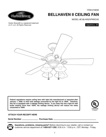
ITEM #18039BELLHAVEN II CEILING FANMODEL #E-BLHII52VPW5C4SHarbor Breeze is a registered trademarkof LF, LLC. All Rights Reserved.español p. 20Federal regulations require ceiling fans with light kits manufactured or imported afterJanuary 1, 2009, to limit total wattage consumed by the light kit to 190W. Therefore,this fan is equipped with a wattage limiting device. If you lamp this fan's light kit withbulbs totaling more than 190W, the wattage limiting device will reduce the wattsconsumed to 190W.E192641ATTACH YOUR RECEIPT HERESerial NumberPurchase DateQuestions, problems, missing parts? Before returning to your retailer, call or contact ourcustomer service department at 1-800-527-1292, 8:30 a.m. - 5:00 p.m., CST, Monday - Friday.1
TABLE OF CONTENTSSafety Information . . .2 - 3Package Contents . . . .4Hardware Contents.5Preparation. . . . . .5Initial InstallationFan MountingWiring. . .6 - 7. .7 - 9. . .9 - 11Final Installation . . . . .11 - 14Operation Instructions. .15 - 16Care and Maintenance . .16TroubleshootingWarranty. . . . .17 - 18 . . .18Replacement Parts List.19SAFETY INFORMATIONREAD AND SAVE THESE INSTRUCTIONSPlease read and understand this entire manual before attempting to assemble, install or operate theproduct. If you have any questions regarding the product, please call customer service at1-800-527-1292, 8:30 a.m. - 5:00 p.m., CST, Monday - Friday. Do not discard fan carton or foam inserts. Should this fan need to be returned to the factory forrepairs, it must be shipped in its original packaging to ensure proper protection against damage thatmight exceed the initial cause for return. Make sure that all electrical connections comply with local codes, ordinances, the National ElectricalCode and ANSI/NFPA 70-1999. Hire a qualified electrician or consult a do-it-yourself wiring handbook,available at Lowe's, if you are unfamiliar with installing electrical wiring. Make sure the installation site you choose allows a minimum clearance of 7 feet from the blades tothe floor and at least 30 in. from the end of the blades to any obstruction. After you install the fan, make sure that all connections are secure to prevent the fan from falling. The net weight of this fan including the light kit is: 25 lbs. (11.34 kg).2
SAFETY INFORMATIONWARNINGSTo reduce the risk of fire, electrical shock, or personal injury, mount fan to outlet boxmarked "ACCEPTABLE FOR FAN SUPPORT OF 35 LBS (15.9 KG) OR LESS" and usemounting screws provided with the outlet box. Most outlet boxes commonly used for thesupport of lighting fixtures are not acceptable for fan support and may need to be replaced.Consult a qualified electrician if in doubt.When mounting fan to a ceiling outlet box, use a METAL octagonal outlet box. Secure the outletbox directly to the building structure. The outlet box and its support must be able to support themoving weight of the fan (at least 35 lbs.). Do NOT use a plastic outlet box.To avoid personal injury, the use of gloves may be necessary while handling fan parts withsharp edges.To reduce the risk of fire, electrical shock, or personal injury, wire connectors provided with thisfan are designed to accept only one 12-gauge house wire and two lead wires from the fan. If yourhouse wire is larger than 12-gauge or there is more than one house wire to connect to the two fanlead wires, consult an electrician for the proper size wire connectors to use.To reduce the risk of fire or electrical shock, do not use the fan with any solid state speedcontrol device or control fan speed with a full range dimmer switch.To reduce the risk of fire, electrical shock, or personal injury, do not bend the blade arms wheninstalling them, balancing the blades, or cleaning the fan. Do not insert objects between therotating fan blades.To reduce the risk of personal injury, use only parts provided with this fan. The use of partsOTHER than those provided with this fan will void the warranty.CAUTIONSBefore proceeding, be sure to shut off electricity at main switch or circuit breaker in order to avoidelectrical shock.Read all instructions and safety information before installing your new fan. Review theaccompanying assembly diagrams.3
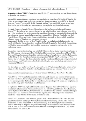
PACKAGE IPTIONDownrodCanopyMounting BracketMotor HousingFitter PlateYoke CoverLight Kit FitterBlade ArmBladeGlass ShadeMotor Screw(preassembled)Lock Y111111155410MCanopy Mounting Screw(preassembled)Pin (preassembled)Clip (preassembledPull Chain ExtensionSocket Ring(preassembled)Finial (preassembled)Candelabra Base BulbCanopy CoverMotor Plate Screw(preassembled)2NOPQRSTU10IMPORTANT REMINDER: You mustuse the parts provided with this fan forproper installation and safety.411241413
HARDWARE CONTENTS (shown actual size)AABBBladeScrewFiberBladeWasherQty. 15CCE3 WireConnectorQty. 15Qty. 4PREPARATIONBefore beginning assembly of product, make sure all parts are present. Compare parts with packagecontents list and hardware contents above. If any part is missing or damaged, do not attempt toassemble the product. Contact customer service for replacement parts.Estimated Assembly Time: 120 minutesTools Required for Assembly (not included): Electrical Tape, Phillips Screwdriver, Pliers, SafetyGlasses, Stepladder and Wire StrippersHelpful Tools (not included): AC Tester Light, Tape Measure, Do-It-Yourself Wiring Handbook(available at Lowe’s) and Wire CuttersBulbs Required (included): 4 candelabra base 40-watt max. bulbsDANGER: When using an existing outlet box, make sure the outlet box is securely attached tothe building structure and can support the full weight of the fan. Failure to do this can result in seriousinjury or death. The stability of the outlet box is essential in minimizing wobble and noise in the fanafter installation is complete.CAUTION: Be sure outlet box is properly grounded and that a ground wire (green or bare) ispresent.After opening top of carton, remove mounting hardware package from foam inserts. Remove motorfrom packing and place on carpet or on foam to avoid damage to finish.CAUTION: Carefully check all screws, bolts and nuts on fan motor assembly to ensure that theyare secured.5
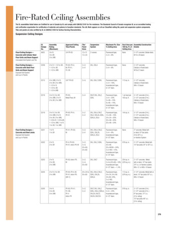
INITIAL INSTALLATION1. Turn off circuit breakers and wall switch to the fansupply line leads. (Fig. 1)1DANGER: Failure to disconnect power supplyprior to installation may result in serious injury ordeath.2. Determine mounting method to use. (Fig. 2)A. Normal mountB. Angle mountImportant: If using the angle mount, check tomake sure the ceiling angle is not steeper than 19 .ONONOFFOFF2AB3. Check to make sure blades (I) are at least 30 in.from any obstruction. Check downrod (A) length toensure blades (I) are at least 7 ft. above the floor.(Fig. 3)330 in.min.I7 ft.min.6
INITIAL INSTALLATION4. Secure mounting bracket (C) to outlet box usingscrews, spring washers, and flat washersprovided with the outlet box. (Fig. 4)*NOTE: It is very important that you use theproper hardware when installing the mountingbracket (C) as this will support the fan.4CIMPORTANT: If using the angle mount, makesure open end of mounting bracket (C) is installedfacing the higher point of the ceiling.5. Remove motor screws (K) and lock washers (L)from underside of motor and save for blade arm(H) attachment later on. [If there are plastic motorblocks installed with the motor screws (K) andlock washers (L), discard the plastic motorblocks.] (Fig. 5)5KLLDFAN MOUNTING1. Remove pin (N) and clip (O) from motor housingyoke at top of motor housing (D) and partiallyloosen set screws. (Fig. 1)*Helpful Hint: Downrod style mounting is bestsuited for ceilings 8 ft. (2.44 m) high or higher.For taller ceilings you may want to use a longerdownrod (not included) than the one provided.Angle style mounting is best suited for angled orvaulted ceilings. A longer downrod is sometimesnecessary to ensure proper blade clearance.1SetScrewODE7N
FAN MOUNTING2. Insert downrod (A) through canopy (B), canopycover (T), and yoke cover (F). [Note: Canopycover (T) must be turned with the shiny sidetoward the motor housing (D).] Thread wiresfrom motor housing (D) through downrod (A).(Fig. 2)2ABTF3. Slip downrod (A) into motor housing yoke, alignholes and re-install pin (N) and clip (O).Re-tighten set screws in motor housing yoke andthen tighten nuts. Slide yoke cover (F) down untilit rests on top of motor housing (D). (Fig. 3)3AFOSet ScrewD4. Depending on the length of downrod (A) youuse, you may need to cut the lead wires back tosimplify the wiring. If you decide to cut back thelead wires, it is suggested that you do so in thefollowing manner:Take the lead wires and make sure that youhave pulled them all the way through the top ofthe downrod (A). Start at the TOP of the ball onthe downrod (A) and measure 8 in. of lead wire,and then cut the excess wire off with wire cutters(not included). (Fig. 4)Note: If you do not cut back the lead wires,Steps 4 and 5 are not necessary and you mayproceed to Step 6 instead.8N4BallA
FAN MOUNTING5. If you decided to cut back the lead wires in Step 4,strip 1/2 in. of insulation from end of white wire.Twist stripped ends of each strand of wire withinthe insulation with pliers (not included). (Fig. 5)Repeat Step 5 for black, blue (if applicable) andgreen wires.6. Install ball end of downrod (A) into mountingbracket (C) opening. Align slot in ball with tab inmounting bracket (C). (Fig. 6)56DANGER: Failure to align slot in ball with tabmay result in serious injury or death.CTabSlotAWIRINGWARNING: To reduce the risk of fire,electrical shock, or personal injury, wireconnectors provided with this fan are designedto accept only one 12-gauge house wire and twolead wires from the fan. If your house wire islarger than 12-gauge or there is more than onehouse wire to connect to the two fan lead wires,consult an electrician for the proper size wireconnectors to use.CAUTION: Be sure outlet box is properlygrounded and that a ground (green or bare) wire ispresent.WARNING: If house wires are differentcolors than referred to in the following steps,stop immediately. A professional electrician isrecommended to determine wiring.9
WIRINGChoose wiring diagram (Fig. 1A, Fig. 1B or Fig.1C) that fits your situation and make appropriatewiring connections as follows: [NOTE: For eachwire connection below, use one of the wireconnectors (CC) provided, making sure to screwwire connector (CC) on in a clockwise direction.]1A. FAN AND LIGHT CONTROLLED BYPULL CHAINS: Connect BLACK and BLUEwire from fan to BLACK wire from ceiling.Connect WHITE wire from fan to WHITE wirefrom ceiling. Connect all GROUND (GREEN)wires together from fan (on downrod (A) andmounting bracket (C)) to BARE/GREEN wirefrom ceiling. (Fig. 1A)FAN AND LIGHT CONTROLLED BY PULL CHAINS1ABLACK120 V PowerFROMCEILINGWHITEGROUND/GREEN (BARE)WHITEGREENBLACKFANBLUEGREENWHITEFROM FAN1B. FAN CONTROLLED BY PULL CHAIN,LIGHT BY WALL SWITCH: If you intend tocontrol the fan light with a separate wallswitch, connect BLACK wire from fan toBLACK wire from ceiling. Connect BLUE wirefrom fan to the BLACK wire from theindependent wall switch for the light. ConnectWHITE wire from fan to WHITE wire fromceiling. Connect all GROUND (GREEN) wirestogether from fan (on downrod (A) andmounting bracket (C)) to BARE/GREEN wirefrom ceiling. (Fig. 1B)FAN CONTROLLED BY PULL CHAIN, LIGHT BYWALL SWITCH41BBLACKBLACK (WALL SWITCH)120 V PowerFROMCEILINGWHITEGROUND/GREEN (BARE)WHITEBLUEGREENBLACKFANGREENFROM FAN1C. FAN AND LIGHT CONTROLLED BYTWO WALL SWITCHES: If you intend tocontrol the fan and light with separate wallswitches, connect BLACK wire from fan toBLACK wire from the independent wall switchfor the fan. Connect BLUE wire from fan to theBLACK wire from the other independent wallswitch for the light. Connect WHITE wire fromfan to WHITE wire from ceiling. Connect allGROUND (GREEN) wires together from fan(on downrod (A) and mounting bracket (C)) toBARE/GREEN wire from ceiling. (Fig. 1C)WHITEFAN AND LIGHT CONTROLLED BY TWO WALLSWITCHES1CBLACK (WALL SWITCH)120 V PowerFROMCEILINGBLACK (WALL SWITCH FOR LIGHT)WHITEGROUND/GREEN (BARE)WHITEBLUEGREENBLACKFANNOTE: Black wire is hot power for fan. Blue wireis hot power for light kit. White wire is commonfor fan and light kit. Green or bare wire is ground.10GREENFROM FANWHITE
WIRING2. Wrap electrical tape (not included) around eachindividual wire connector (CC) down to the wire asshown in Fig. 2.WARNING: Make sure no bare wire or wirestrands are visible after making connections. Placegreen and white connections on opposite side of boxfrom the black and blue (if applicable) connections.2CCCCCCTurn spliced/taped wires upward and gently pushwires and wire connectors (CC) into outlet box.CCHardware UsedCC E3 Wire Connectorx43. IMPORTANT: Using a full range dimmer switch(not included) to control fan speed will cause a loudhumming noise from fan. To reduce the risk of fireor electrical shock, do NOT use a full rangedimmer switch to control fan speed. (Fig. 3)3321DimmerSwitchSpeedSwitchFor illustrative purposes only--notintended to cover all types of controlsFINAL INSTALLATION1. Locate two canopy mounting screws (M) onunderside of mounting bracket (C) and removecanopy mounting screw (M) closest to the open endof of the mounting bracket (C). Partially loosen theother canopy mounting screw (M). Lift canopy (B) tomounting bracket (C). Place rounded part of slottedhole in canopy (B) over loosened canopy mountingscrew (M) in mounting bracket (C) and push up.Twist canopy (B) to lock. Re-insert canopymounting screw (M) that was removed, and thentighten both canopy mounting screws (M) securely.Slide canopy cover (T) up to canopy (B), aligningrounded part of slotted holes in canopy cover (T)with screwheads in bottom of canopy (B). Turncanopy cover (T) to the right (clockwise) until itstops. (Fig. 1)111BAMT
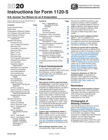
FINAL INSTALLATION2. Partially insert three blade screws (AA), along withthree fiber blade washers (BB), to attach one bladearm (H) to a blade (I). Then, tighten each bladescrew (AA) starting with the one in the middle.(Fig. 2) Repeat with remaining blades (I).2AAIBBHardware UsedAA Blade Screwx15BB Fiber Blade Washerx153. Locate motor screws (K) and lock washers (L) thatwere removed in Step 5 on page 7.H3Insert two motor screws (K), along with lockwashers (L), through one blade arm (H) to attachblade arm (H) to motor. Tighten motor screws (K)securely. (Fig. 3) Repeat with remaining blade arms(H), making sure to completely secure each bladearm (H) before proceeding with the next.LK4. Partially loosen two motor plate screws (U) onunderside of motor and remove the other motorplate screw (U). Align slotted holes in fitter plate(E) with loosened motor plate screws (U) on motorplate, allowing male plug from motor housing (D)to come through square hole in fitter plate (E).Twist fitter plate (E) to lock. Re-insert the motorplate screw (U) that was removed and securelytighten all three motor plate screws (U). (Fig. 4)H4DmotorplateMalePlugEU12
FINAL INSTALLATION5. Remove finial (R) from threaded rod on fitterplate (E). (Fig. 5) Save finial (R) for later use.5ER6. Connect male plug from motor housing (D) tofemale plug from light kit fitter (G), matching upthe colors on the male plug with the colors onthe female plug for correct fit. Make sure plugsare connected completely. (Fig. 6)6DMalePlugFemalePlugG7. Align hole in center of light kit fitter (G) withthreaded rod on fitter plate (E) and push upgently until threaded rod comes through hole.Secure light kit fitter (G) with finial (R) thatwas previously removed. (Fig. 7)7EGR13ThreadedRod
FINAL INSTALLATION8. Remove socket rings (Q) from sockets. Attachglass shades (J) with socket rings (Q). (Fig. 8)8Note: Do not overtighten socket rings (Q) asglass may crack or break.Q9. Install four candelabra base 40-watt max. bulbs(S) included. (Fig. 9)J9Important: When you need to replace bulbs,please allow bulb(s) and glass shade(s) to cooldown before touching them.SS10. The pull chain extensions (P) supplied in one ofthe hardware packs or custom pull chainextensions (not included) may be attached to fanand light pull chains. (Fig. 10)10NOTE: This fan is remote control adaptable(remote control not included).P14
OPERATION INSTRUCTIONS1.The pull chain labeled SPEED has fourpositions to control fan speed. One pull isHIGH, two is MEDIUM, three is LOW and fourturns the fan OFF. (Fig. 1)12. The pull chain labeled LIGHT is used to turn thelights ON or OFF. (Fig. 2)23. Use the fan reverse switch, located on theswitch housing, to optimize your fan forseasonal performance. (Fig. 3) A ceiling fanwill allow you to raise your thermostat settingin summer and lower your thermostat setting inwinter without feeling a difference in yourcomfort.3Note: Wait for fan to stop before moving thereverse switch.15SwitchHousing
OPERATION INSTRUCTIONS3A. In warmer weather, setting the reverse switchin the LEFT position will result in downward airflowcreating a wind chill effect. (Fig. 3A)3A3B3B. In cooler weather, setting the reverse switchin the RIGHT position will result in upward airflowthat can help move stagnant, hot air off the ceilingarea. (Fig. 3B)3C. IMPORTANT: Reverse switch must be seteither completely LEFT or completely RIGHT forfan to function. If the reverse switch is set in themiddle position (Fig. 3C), fan will not operate.3CCARE AND MAINTENANCEAt least twice each year, lower canopy (B) to check downrod (A) assembly, and then tighten all screwson the fan. Clean motor housing (D) with only a soft brush or lint-free cloth to avoid scratching thefinish. Clean blades (I) with a lint-free cloth. You may occasionally apply a light coat of furniture polishto wood blades for added protection.Important: Shut off main power supply before beginning any maintenance. Do not use water or adamp cloth to clean the ceiling fan.16
TROUBLESHOOTINGIf you have any questions regarding the product, please call customer service at 1-800-527-1292,8:30 a.m. - 5 p.m., CST, Monday - Friday. Warning: Before beginning work, shut off the power supply to avoid electrical shock.PROBLEMFan does not move.POSSIBLE CAUSECORRECTIVE ACTION1. Reverse switch not engaged.1. Push switch firmly either left orright.2. Turn power on or check fuse.3. Turn power off. Loosen canopy(B) and check all connections.4. Check that male and femaleplugs in light kit fitter (G) areconnected properly according toinstructions on page 13.2. Power is off or fuse is blown.3. Faulty wire connection.4. Plugs not connected properly.Noisy operation.1. Blades (I) are loose.2. Cracked blade (I).3. Full range dimmer switch.4. Fan is new.Excessive wobbling.1. Blades (I) are loose.2. Blade arms (H) incorrectly attached.3. Unbalanced blades (I).4. Fan not securely mounted.5. Fan too close to vaulted ceiling.6. Set screw(s) on motor housing yokeis (are) not tightened properly.7. Set screw on hanging ball is nottightened properly.Fan operates butlight fails.1. Bulb(s) not installed correctly.2. Wires in canopy (B) not wiredproperly.3. Wall switch to fan is off.4. Plugs not connected properly.171. Tighten all blade screws (AA).2. Replace blade (I).3. Replace with an approvedspeed control device.4. Allow fan a “break in” period of afew days, especially when runningthe fan at Medium and Highspeeds.1. Tighten all blade screws (AA).2. Re-install blade arms (H).3. Switch one blade (I) with a blade(I) from the opposite side.4. Turn power off. Carefully loosencanopy (B) and verify thatmounting bracket (C) is secure.5. Use a longer downrod (A) ormove fan to another location.6. Tighten yoke set screw(s)securely.7. Carefully loosen and lowercanopy (B) and verify that setscrew on hanging ball is tightenedsecurely.1. Re-install bulb(s).2. Check wires in canopy (B) and,if necessary, re-wire according toinstructions on pages 10 and 11.3. Make sure that wall switch to fanis on.4. Check that male and femaleplugs in switch housing areconnected properly according toinstructions on page 13.
TROUBLESHOOTINGPROBLEMLights dim when turningfan and/or lights on.POSSIBLE CAUSE1. Fan is lamped with more than190W and fan was turned off atwall switch, causing the wattagelimiting device to re-set itself.2. Fan is lampled with more than190W causing the wattage limitingdevice in fan to re-set itself due topower outage.Lights appear dimmerthan they should.1.Fan is lamped with more than190W and wattage limitingdevice is reducing the amount ofwattage produced by the light kit.CORRECTIVE ACTION1. No action necessary--fan willautomatically re-set within 5seconds after turning wall switchback on.2. No action necessary--fan willautomatically re-set within 5seconds after turning power backon.Note: In order to avoid thisproblem, fan may be lamped withbulbs totaling no more than 190W.1.Lamp light kit with bulbs that totalno more than 190W.Note: A small amount of "wobble" is normal and should not be considered a defect.WARRANTYLIMITED LIFETIME WARRANTY: Litex Industries warrants this fan to be free from defects inworkmanship and materials present at time of shipment from the factory for Lifetime limited from thedate of purchase. This warranty applies only to the original purchaser. Litex Industries agrees tocorrect any defect at no charge or, at our option, replace the ceiling fan with a comparable or superiormodel.To obtain warranty service, present a copy of your sales receipt as proof of purchase. All cost ofremoval and reinstallation are the express responsibility of the purchaser. Any damage to the ceilingfan by accident, misuse or improper installation, or by using parts not produced by the manufacturerof this fan or affixing accessories not produced by the manufacturer of this fan, are the purchaser'sown responsibility. Litex Industries assumes no responsibility whatsoever for fan installation duringthe limited lifetime warranty. Any service performed by an unauthorized person will render thewarranty invalid.Due to varying climatic conditions, this warranty does not cover changes in brass finish, rusting,pitting, tarnishing, corroding or peeling. Brass finish fans maintain their beauty when protected fromvarying weather conditions. Any glass provided with this fan is not covered by the warranty.Any replacement of defective parts for the ceiling fan must be reported within the first year from thedate of purchase. For the balance of the warranty, call our customer service department (at1-800-527-1292) for return authorization and shipping instructions so that we may repair or replacethe ceiling fan. Any fan or parts returned improperly packaged is/are the sole responsibility of thepurchaser. There is no further express warranty. Litex Industries disclaims any and all impliedwarranties. The duration of any implied warranty which cannot be disclaimed is limited to the limitedlifetime period as specified in our warranty. Litex Industries shall not be liable for incidental,consequential or special damages arising at or in connection with product use or performance exceptas may otherwise be accorded by law. This warranty gives you specific legal rights and you may alsohave other rights which vary from state to state. This warranty supersedes all prior warranties.18
REPLACEMENT PARTS LISTFor replacement parts, call our customer service department at 1-800-527-1292, 8:30 a.m. - 5:00 p.m.,CST, Monday - Friday. When ordering parts, please have the Model # or Item # of the fan available,which can be found on page anopyMounting BracketFitter PlateYoke CoverLight Kit FitterBlade ArmBladeGlass ShadeMotor ScrewLock WasherCanopy Mounting ScrewPinClipPull Chain ExtensionSocket RingFinialCanopy CoverMotor Plate ScrewBlade ScrewFiber Blade WasherE3 Wire ConnectorABCEFGHIJKLMNOPQRTAABBCC19Printed in China
ARTICULO #18039VENTILADOR DE TECHO BELLHAVEN IIMODELO #E-BLHII52VPW5C4SHarbor Breeze es marca registrada de LF,LLC. Reservados todos los derechos.El reglamento federal requiere que un ventilador de techo con juego de luz fabricado oimportado después del 1ro de enero del 2009 limite el vatiaje total que consume el juegode luz a 190W. Por lo tanto, este ventilador tiene un aparato que sirve para limitar elvatiaje. Si pone bombillas en el juego de luz de este ventilador que suman más de190W, el aparato que sirve para limitar el vatiaje reducirá los vatios consumidos a190W.ADJUNTE SU RECIBO AQUINúmero de serieFecha de compraE192641¿Preguntas, problemas, faltan piezas? Antes de regresar a la tienda, llame o póngase encontacto con nuestro departamento de servicio al cliente al 1-800-527-1292, de 8:30 a.m. a5:00 p.m., hora central, de lunes a viernes.20
INDICE DE MATERIAS . . .21 - 22Información de seguridadContenido del paquete . .23Contenido de artículos de ferreteríaPreparación. . . . . . .24Instalación inicial. .25 - 26Montaje del ventilador.26 - 28Conexión de los cablesInstalación final . .28 - 31 . . . . . . .31 - 34Instrucciones de funcionamientoCuidado y mantenimientoLocalización de fallasGarantía.24. .35 - 36. . .36. . . . .37 - 38. . . . .39Lista de piezas de repuestos.40INFORMACION DE SEGURIDADPOR FAVOR LEA Y GUARDE ESTAS INSTRUCCIONESPor favor lea el instructivo entero antes de tratar de ensamblar, instalar o hacer funcionar el producto. Sitiene alguna pregunta acerca del producto, por favor llame al servicio al cliente al 1-800-527-1292, de 8:30a.m. a 5:00 p.m., hora central, de lunes a viernes. No deseche la caja del ventilador ni la goma espuma incluida. Si hay que mandar el ventilador a lafábrica por alguna reparación, se debe enviar en su paquete original para asegurar la protección apropiadacontra daños que podrían exceder la causa inicial por la cual se devolvió. Asegúrese de que todas las conexiones eléctricas cumplen con los códigos y las ordenanzas locales, conel Código Nacional Eléctrico (NEC, por sus siglas en inglés), y ANSI/NFPA 70-1999. Contrate unelectricista calificado o consulte una guía de instalación eléctrica de hágalo usted mismo, disponible enLowe's, si no está familiarizado con la instalación eléctrica. Asegúrese de que el lugar de instalación que usted escogió tiene un mínimo de 2,13 m de desde laspaletas hasta el piso y que la punta de las paletas quede a por lo menos 76,2 cm de cualquier obstrucción. Después de instalar el ventilador, verifique que todas las conexiones estén seguras para que no se caigael ventilador. El peso neto del ventilador con el juego de luz es de: 11,34 kg.21
INFORMACION DE SEGURIDADADVERTENCIASPara reducir el riesgo de incendio, choque eléctrico o daño corporal, sujete el ventiladora una caja de salida marcada "Aceptable para sostener ventilador" ("ACCEPTABLE FORFAN SUPPORT" en inglés) y use los tornillos de montaje proporcionados con la caja desalida. La mayoría de las cajas de salida que se usan comúnmente para sostener aparatos dealumbrado no son aceptables para sostener ventiladores y es posible que sea necesarioreemplazarla. Consulte con un electricista calificado si tiene alguna duda.Al instalar el ventilador a una caja de salida de techo, use una caja de salida de METALoctagonal. Asegure la caja de salida directamente a la estructura del edificio. La caja de salida yel soporte deben ser capaces de sostener el peso móvil del ventilador (por lo menos 15,88 kg).NO use una caja de salida de plástico.Para reducir el riesgo de daño corporal, es posible que sea necesario usar guantes al manejarlas piezas del ventilador que tengan bordes afilados.Para reducir el riesgo de incendio, choque eléctrico o daño corporal, los conectores para cableprovistos con este ventilador son diseñados para aceptar sólo un cable de calibre 12 de la casa ydos cables principales del ventilador. Si el calibre del cable de la casa es superior al 12 o haymás de un cable de la casa para conectar a los cables principales del ventilador, consulte con unelectricista para informarse sobre el tamaño correcto de conectores para cable que se debe usar.Para reducir el riesgo de incendio o un choque eléctrico, no use el ventilador con ningúncontrol de velocidad de estado sólido ni controle la velocidad del ventilador con uninterruptor con reductor de luz de gama completa.Para reducir el riesgo de incendio, choque eléctrico o lesión personal, no doble brazos de laspaletas mientras las esté instalando, ni cuando esté balanceando las paletas ni cuando estélimpiando el ventilador. No inserte objetos entre las paletas giratorias del venti
Questions, problems, missing parts? Before returning to your retailer, call or contact our customer service department at 1-800-527-1292, 8:30 a.m. - 5:00 p.m., CST, Monday - Friday. Harbor Breeze is a registered trademark