Transcription
Rev. July 13, 2020Distributed System Speaker Spacingfor the Integratorby Joe Ging, E.E. 2019 Lowell Manufacturing Company100 Integram Drive, Pacific, Mo. 63069 USA(636) 257-3400 www.lowellmfg.com
INDEX1Introductionpg. 32Speaker Dispersionpg. 43Inverse-Square Lawpg. 54Calculating Distributed Speaker Spacingpg. 75Rule-of-thumb Formulaspg. 86Examplespg. 97Summarypg. 138Appendix Apg. 142 DISTRIBUTED SPEAKER SPACING FOR THE INTEGRATOR
INTRODUCTIONIn this paper, we will discuss how to use simple rule-of-thumb formulas to properly space ceilingspeakers that are shooting straight down at the floor in a distributed speaker system. Before webegin that discussion, it is important to have a clear understanding of a specification that we call“Speaker Dispersion.”DISTRIBUTED SPEAKER SPACING FOR THE INTEGRATOR 3
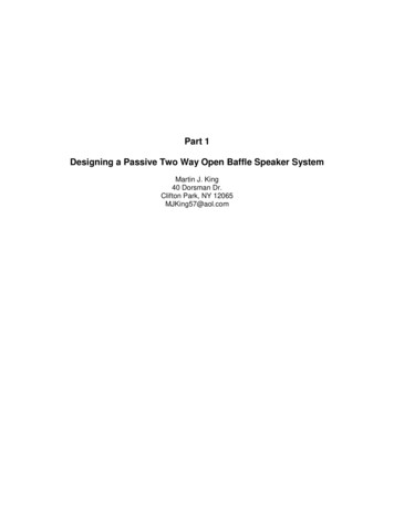
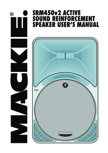
SPEAKER DISPERSIONConical Dispersion: By definition, “Conical Dispersion” is the coverage angle of a speakermeasured at an equal distance from the speaker where the sound pressure level (SPL) at the2kHz octave band (important for speech articulation) is no more than 6dB lower than the SPL onaxis (straight out in front of the speaker). Conical Dispersion is shown on the left in the drawingbelow with the black arrows showing the conical -6dB down points.It is common industry practice for audio manufacturers to give a Conical Dispersion specificationfor loudspeakers. It’s easy to see on the drawing on the left above, that for a wide dispersionspeaker, the conical -6dB measurement points will be up in the air, far above the average listeningheight. Because it is the industry standard, Conical Dispersion is given on Lowell Manufacturingspec sheets so that our speaker specifications can be compared to those of our competition, butit’s obvious from the drawing above that we can’t calculate speaker spacing based onmeasurement points that are up in the air. On the Conical Dispersion drawing shown on the leftabove, the red arrows show that at the average listening height, the actual SPL is more like 12dB. What is really important for speaker spacing is the -6dB points at the average listeningheight where the sound is actually heard by the listeners. At Lowell Manufacturing, we call theangle of dispersion with the -6dB points calculated at the average listening height the “LinearDispersion” as shown on the right in the drawing above. Lowell offers both the Conical Dispersionand the Linear Dispersion on specification sheets.For the remainder of this article, when speaker dispersion “D” is called for in a rule-of-thumbformula, we will always be referring to the Linear Dispersion angle that is listed on the Lowellspecification sheets, not the Conical Dispersion angle.4 DISTRIBUTED SPEAKER SPACING FOR THE INTEGRATOR
Linear Dispersion: The “Linear Dispersion” angle is usually narrower than the “ConicalDispersion” angle. To understand why, we need to look at an acoustic law of Physics called theInverse-Square Law.The Inverse-Square Law is based on the fact that a sound wave emitted by a loudspeaker travelsas a sphere away from the loudspeaker. The formula for the area of a sphere is 4pr2. That meansthat as the distance from the speaker (the radius “r”) doubles, the area of the sphere that thesound from the speaker has to cover is 4 times as large because the radius term in the formulais “squared”.In the formula for sound pressure level, the sound energy from the speaker is divided by the areaof the sphere to find the SPL at a certain point. Note that if X Y/Z, that is the samemathematically as X 1/Z times Y. In math terms, 1/Z is called the inverse. In the sound pressurelevel formula, the sphere area 4pr2 is in the denominator of the formula, so that is mathematicallythe same as an inverse. In other words, the squared radius term is an inverse in the SPL formulaand that’s where the Inverse-Square Law gets its name.Inverse-Square Law: SPL2 SPL1 – 20 log (D2/D1) SPL1 is the sound pressure level at the first location.SPL2 is the sound pressure level at the second location.D1 is the distance from the speaker at the first location.D2 is the distance from the speaker at the second location.The Inverse-Square Law says that every time you double the distance from the speaker, thesound pressure level decreases by 6.02dB (most sound guys just round that off to 6dB).Loudspeakers typically have their highest SPL directly “on-axis” (straight out from the face of thespeaker). “Off-axis” (off to the side), the speaker typically isn’t as loud and the SPL typicallydecreases the farther off-axis the listener moves. In a Conical Dispersion measurement, thedistance from the measuring test microphone to the speaker is always the same so the SPLdecreases only as the off-axis SPL from the speaker decreases.In a Linear Dispersion measurement, the microphone is closest to the speaker when it is on-axis(directly out from the speaker). As the microphone moves at the listening height to the side (offaxis) the distance from the microphone to the speaker increases. In a Linear Dispersionmeasurement, there will still be the SPL decreases because the off-axis SPL from the speakerdecreases compared to the on-axis SPL, but at the same time, as soon as the measurement micmoves away from being directly on-axis, D2 is greater because the distance from the speaker tothe average listening height is farther than D1 (the on-axis distance), so there will also be inversesquare distance losses and they will increase dramatically the farther the Linear Dispersionmeasurement is taken off-axis.One might think if you are using a speaker like the Lowell JR410 with a Conical Dispersion of 170degrees, that one speaker should be able to cover the whole room, but that kind of thinking doesnot take into consideration the inverse-square losses due to distance. At 85 degrees off axis, theJR410 is shooting sound almost sideways, but as we all know, sound doesn’t travel forever. Bythe time that sound at 85 degrees off axis travels far enough to reach the average listening height,the sound pressure level (SPL) has been reduced to the point that it can’t even be heard. Only byusing the Linear Dispersion specification in the formulas to determine speaker spacing will youget an accurate representation of the SPL at the average listening height (where the listener’sears are).DISTRIBUTED SPEAKER SPACING FOR THE INTEGRATOR 5
A few examples can illustrate the importance of the Linear Dispersion specification:Example 1: Consider the Lowell 12P150 driver (12” compression driver coaxial speaker). TheConical Dispersion is a very narrow 70 degrees. The Linear Dispersion, however, is only 60degrees so that is the dispersion specification that should be used in any rule-of-thumb formulasfor distributed speaker spacing.Example 2: Consider the Lowell JR410 driver (4” single cone). The Conical Dispersion is a verywide 170 degrees. The Linear Dispersion, however, is only 100 degrees so that is the dispersionspecification that should be used in any rule-of-thumb formulas for distributed speaker spacing.Many contractors plug the Conical Dispersion angle (given by most manufacturers) into theirspeaker spacing formulas. It’s obvious from the examples given above that using the ConicalDispersion in spacing formulas does not give an accurate result, especially for very widedispersion speakers. Using the Conical Dispersion angle in rule-of-thumb spacing designformulas can result in a speaker system with huge dead spot holes in the speaker coverage.6 DISTRIBUTED SPEAKER SPACING FOR THE INTEGRATOR
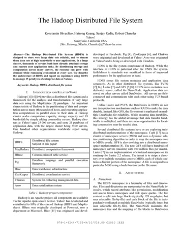
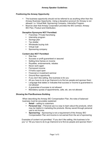
CALCULATING DISTRIBUTED SPEAKER SPACINGWhen sound system designers lay out the speaker spacing for a distributed paging or musicsystem, they should always consider the speaker coverage at the “listening height” which isdefined as the average height of the listener’s ears. For office sound systems it is usually assumedthat the office workers will be seated at their desks, so the average listening height is generallyconsidered to be 4’ above the finished floor. In an application where the listeners will usually bestanding (like in a museum or a ballroom) the average standing listening height is generallyconsidered to be 5’ above the finished floor.Most system designers consider the minimum coverage pattern that is acceptable for a blanketcovered distributed speaker system to be “Edge-to-Edge Coverage” where the edges of thespeaker’s coverage circles (at the listening height) just touch each other.Take for example a recessed ceiling speaker that has a linear dispersion of 90 degrees at the2kHz octave (the octave most important for speech articulation). For this example, we will assumethe office ceiling height is a standard 9’ from the finished floor. The ceiling height is 9’, minus theaverage listening height at 4’, so that means the speaker has a throw of 5’. With a 90 degreelinear dispersion, we can use some basic trigonometry and know that at a throw of 5’ we can drawa dispersion circle with a diameter of 10’ (at the listening height).The diagram below shows that with Edge-to-Edge Coverage the coverage circles of the speakersjust barely touch. Notice that there are large dead spots between 4 speakers whose coveragecircles touch. For most paging and background music applications, Edge-to-Edge Coverage isacceptable.Once we start talking about higher quality foreground music, we want to close those dead spotsso it is wise to consider “Minimum-Overlap Coverage” as shown above. Note that it takes a lotmore speakers to produce Minimum-Overlap Coverage where there are no dead spots betweenspeakers.For extremely high quality pro sound systems, some designers will use “Edge-to-CenterCoverage” where the dispersion circle from one speaker extends to the center of the adjacentspeaker as shown above. The sound pressure level will be very uniform at the listening height,but notice that Edge-to-Center Coverage requires roughly 4 times the number of speakers thatare required for Edge-to-Edge Coverage. It becomes clear why, for cost reasons, Edge-to-EdgeCoverage is what is used most often by integrators for paging and background music systems.DISTRIBUTED SPEAKER SPACING FOR THE INTEGRATOR 7
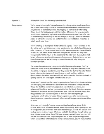
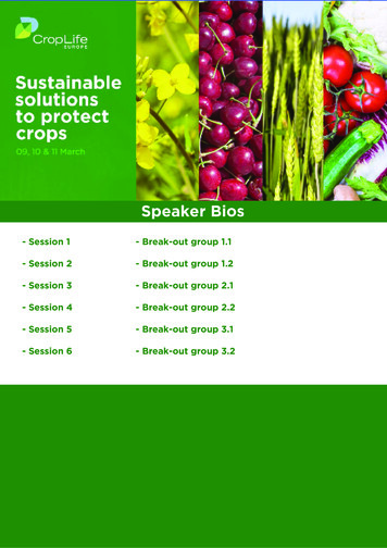
RULE-OF-THUMB FORMULAS for DISTRIBUTED SPEAKER SPACING H Height of the speaker face above the floorL Average listening height (Typically 4’ for seated listeners and 5’ for standing listeners)D Linear dispersion angle of the speaker (The -6db point dispersion angle at listening level)TAN The trigonometric tangent function on your calculatorNote: The rule-of-thumb formulas given above are for square speaker spacing. Hexagonalspeaker spacing formulas are also available, but they are difficult for the contractor to lay out ondrawings and it is even harder for the typical installer to space speakers out in a hexagonal patternin the field, so we are not recommending their use.8 DISTRIBUTED SPEAKER SPACING FOR THE INTEGRATOR
SPEAKER SPACING EXAMPLESExample 1: System will be for paging and background music in an office setting. Finished layin tile ceiling is 9’ from the finished floor. I will design for square Edge-to-Edge spacing. Speaker chosen: Lowell ES-4TConical Dispersion: 175 degrees, Linear Dispersion: 95 degreesEdge-to-Edge speaker spacing 2 (H–L) TAN (1/2 D)H 9’. L 4’ (seated listening height) D 95 degreesEdge-to-Edge speaker spacing 2 (9’–4’) TAN (47.5 degrees) 10.9’For the speakers to fit in the ceiling tiles, I need to either space my speakers on 10’ centers or 12’centers. The application isn’t super critical but I don’t want to offer less than Edge-to-Edgecoverage so I decide to go with 10’ centers. To lay out my speakers, I come in 5’ from the sidewall and 5’ from the rear wall (or as close as possible depending on the layout of the ceiling tile.I put a row with one speaker every 10’. Then I move over 10’ and put a second row with onespeaker every 10’. If that pattern doesn’t fit in the room where I have 5’ to the other side wall, Iwould typically scoot the pattern over so there is a little extra space near the outside walls wheretypically nobody would be sitting.Another option would be that I feel that since the application isn’t super critical I decide that it willbe acceptable to offer slightly less that Edge-to-Edge coverage so I go with 12’ centers. To layout my speakers I come in 6’ from the side wall and 6’ from the rear wall (or as close as possibledepending on the layout of the ceiling tile). I put a row with one speaker every 12’. Then I moveover 12’ and put a second row with one speaker every 12’. If that pattern doesn’t fit in the roomso I have 6’ to the other side wall, I would typically scoot the pattern over so there is a little extraspace near the outside walls where typically nobody would be sitting.Bidding Short-Cut: Often in a bidding situation, the number of speakers for a given area needsto be determined quickly and there is no time to do a complete speaker layout. Using the exampleabove, for square edge-to-edge spacing, if we have determined that we are going to space thespeakers on 10’ center-to-center spacing, that means that every speaker is going to cover asquare area that is 10’ X 10’ (including the dead spots between speakers). That means that everyspeaker will cover 100 square feet. If we are given that the office space is a total of 30,000 sq. ft.,then by dividing 30,000 sq. ft. by 100 sq. ft. approximately 300 speakers are required.DISTRIBUTED SPEAKER SPACING FOR THE INTEGRATOR 9
Example 2: System will be for foreground music in a restaurant setting. Finished lay-in tile ceilingis 12’ from the finished floor. This is a high-end restaurant so I want to have super even coveragewith no dead spots. I will design for square Minimum-Overlap spacing. Speaker chosen: Lowell ES-62TConical Dispersion: 120 degrees, Linear Dispersion: 90 degreesMinimum-Overlap speaker spacing 1.5 (H - L) TAN (1/2 D)H 12’. L 4’ (seated listening height) D 90 degreesMinimum
speaker’s coverage circles (at the listening height) just touch each other. Take for example a recessed ceiling speaker that has a linear dispersion of 90 degrees at the 2kHz octave (the octave most important for speech articulation). For this example, we will assume the office ceiling height is a standard 9’ from the finished floor. The ceiling height is 9’, minus the average listening .