Transcription
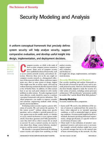
International Journal of Engineering Research & Technology (IJERT)ISSN: 2278-0181Vol. 6 Issue 07, July - 2017Published by :http://www.ijert.orgModeling and Analysis of Cotter JointAshokrao ShindeOmkar Chandrakant Vibhute,Department of Mechanical Engineering,DKTE’S Textile and Engineering Institute,Ichalkaranji.Department of Mechanical Engineering,DKTE’S Textile and Engineering Institute,Ichalkaranji.Abstract: The subject of this project is the modeling andanalysis of cotter joint. Cotter joint is used to connect tworods subjected to axial tensile or compressive loads. Cotterjoint is widely used to connect the piston rod and cross head ofthe steam engine, so as a joint between the piston rod and thetailor pump rod, foundation bolt etc. Failure of cotter jointmay causes accident, so it is necessary to design cotter joint towithstand under tension without failure the effective design ofmechanical device or assembly demand the predictiveknowledge of its behavior in working condition. In this projectwe use theoretical method for finding dimensions of cotterjoint. After the design of cotter joint, The modeling of cotterjoint is done by using 3D software. Here we will be usingCATIA V5R19 for modeling. After modeling on CATIA, wewill analyze cotter joint on software named as “ANSYS V15”.Keywords— Cotter joint, Design, Modeling, Analysi ,CATIAV5R20, ANSYS R15.1. INTRODUCTIONThe Failure of cotter joint may causes accident so it isnecessary to design cotter joint to withstand under tensionwithout failure. The effective design of mechanical deviceor assembly demand the predictive knowledge of itsbehavior in working condition. It became necessary for thedesigner to know the forces and stress developed during itsoperation. In this project we use theoretical method forfinding dimensions of cotter joint. After the design of cotterjoint, the modeling of cotter joint is done by using CATIAV5R20. Here we will be using CATIA V5R19 formodeling. After modeling on CATIA V5R19, We willanalyze cotter joint on software named as “ANSYS V15”.A cotter is a flat wedge shaped piece of rectangularcross-section and its width is tapered (Either on one side orboth sides) from one end to another for an easy adjustment.The taper varies from 1 in 48 to 1 in 24 and it may beincreased up to 1 in 8, If a locking device is provided. Thelocking device may be a taper pin or a set screw used onthe lower end of the cotter. The cotter is usually made ofmild steel or wrought iron. A cotter joint is a temporaryfastening and is used to connect rigidly two co-axial rods orbars which are subjected to axial tensile or compressiveforces. It is usually used in connecting a piston rod to thecross- head of a reciprocating steam engine, A piston rodand its extension as a tail or pump rod, Strap end ofconnecting rod etc. [6]IJERTV6IS070202Fig 1: Cotter joint2. LITURATURE SURVEYShaikh J, vanka H, “Modeling and analysis ofknuckle joint”, International journal & magazine ofengineering. They have completed Modeling and analysisby using advanced modeling software system CATIA andANSYS respectively. The knuckle joint is a type of jointwhich is used in steering system in between steering rodand steering gear. In this joint is employed here in order toget the maximum productivity and manufacturingtechnology must not be stiff. FMS (Flexible ManufacturingSystem) is used in order to gain the advantage over simplemanufacturing of knuckle joint. Final dimension fromtheoretical calculation of knuckle joint. Model of knucklejoint is made in CATIA V5 and that model is taken toANSYS and stimulated with various material and check forbest material which suit for given design load. From resultTeflon is best material for design and it close to stress gotfrom stainless steel and cast iron with less manufacturingcost. [1]Saxena N, Rajvaidya R, “Study and analysis ofknuckle joint with the replacement of material by usingTeflon”, journal of engineering research & application, Theobjective of this paper is to study the various stresses andstrain by replacing of material by using Teflon. In manyindustries use knuckle joint which is combination of twomaterials cast iron is stainless steel. In this paper thereplacement of cast iron into composite polymer material,Polymer is the most similar to property of metal.Composite polymers are characterized by a high flexibilitymaterial they conclusion that the result appropriate equal orcloser theoretical and ANYSYS-13. [3]Ravindra S. Dharpure, Prof D. M. Mate, “Study andAnalysis of Pin of Knuckle Joint In Train”, The mainmotive of this paper is to improve the performance of theknuckle pin in the couplings of the railway couplings. Thecurrent mechanism of coupling is briefly defined andmethodologically treatment is determined for failure ofwww.ijert.org(This work is licensed under a Creative Commons Attribution 4.0 International License.)338
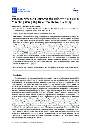
Published by :http://www.ijert.orgInternational Journal of Engineering Research & Technology (IJERT)ISSN: 2278-0181Vol. 6 Issue 07, July - 2017knuckle pin in the coupling. The aim of this chapter is toconceptually define remedy for the failure problem of theknuckle coupling. As per the company’s presentrequirement the cotter joint should be efficiently used toreduce the cost of production, improve the quality of theproduct, Increase the production rate and Increase theservice life of the cotter joint.3. METHODOLOGYThe main objective of the study is to check whetherthe cotter joint is withstanding the load applied during theworking condition or not.So the methodology of the study includes1. CAD Model of cotter joint using CATIAV5R20.2. Design of cotter joint.3. CAD Model of cotter joint assembly.4. Meshing of cotter joint using ANSYS R15.5. Elemental analysis at various loads.6. Result and Conclusion.4.DESIGN OF COTTER JOINTFig.2: Socket and spigot cotter jointThe socket and spigot cotter joint is shown in Fig 2.Let,P Load carried by the rods,D Diameter of the rods,d1 Outside diameter of socket,d2 Diameter of spigot or inside diameter of socket,d3 Outside diameter of spigot collar,t1 Thickness of spigot collar,d4 Diameter of socket collar,c Thickness of socket collar,b Mean width of cotter,t Thickness of cotter,l Length of cotter,a Distance from the end of the slot to the end of rod,σt Permissible tensile stress for the rods material,τ Permissible shear stress for the cotter material,σc Permissible crushing stress for the cotter material.The rods are subjected to tensile force andstrength is the criterion for the selection of the rodmaterial. The cotter is subjected to direct shear stressand bending stresses. Therefore strength is also thecriterion of material selection for the cotter. On thebasis of strength, the material of the two rods and thecotter is selected as plain carbon steel of Grade 30C8(Syt 400N/mm2) [7]To account for these factors, a higher factor of safetyis used in the present design. The factor of safety for therods, spigot end and socket end is assumed as 6, while forthe cotter, It is taken as 4 there are two reasons forassuming a lower factor of safety for the cotter.IJERTV6IS070202(1) There is no stress concentration in the cotter.(2) The cost of the cotter is small compared with socketend or spigot end.Calculation of permissible stressesThe permissible stresses for rods, spigot end andsocket end are as followsσt sytσ c τ 400/6 66.67 N/mm2fs2syt 2*400/6 133.33 N/mm2fs0.5sytfs 0.5*400/6 33.33 N/mm2Permissible stresses for the cotterσt τ syt 400/4 100 N/mm2fs0.5sytfs 0.5*400/4 50 N/mm2Dimensions of rodd 32 mmThickness of cottert 10 mmDiameter of spigotd2 40 mmOuter diameter of socketd1 55 mmDiameter of spigot and socket collard3 48 mm andd4 80 mma c 24 mmWidth of cotterb 50 mmThickness of spigot collart1 15 mmTaper of cotter is 1 in 32 [7]5. MODELLING OF COTTER JOINT3D Modeling is used in a variety of applications to makerepresentations of physical objects on the computer. 3Dmodeling is a subset of Computer Aided Design (CAD), Inwhich you use a computer to assist in the design processfor any type of design work. It is used in a variety ofapplications, Mostly when it comes to designing parts onthe computer to assist in the making or visualization ofthose parts. The computer model is used to communicatedimensions, material types, etc. To anyone viewing thedesign. CATIA (Computer Aided Three DimensionalInteractive Application) is a multi-platform software suitedeveloped by the French company Dassault Systems.CATIA enables the creation of 3D parts, from 2D sketches,sheet metal, composites, and molded, Forged or toolingparts up to the definition of mechanical assemblies. Thesoftware provides advanced technologies for mechanicalsurfacing. It provides tools to complete product definition,including functional tolerances as well as kinematicsdefinition. CATIA provides a wide range of applicationsfor tooling design, for both generic tooling and mould&die. [2]www.ijert.org(This work is licensed under a Creative Commons Attribution 4.0 International License.)339
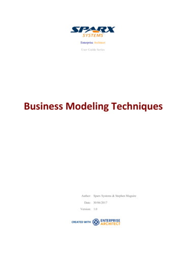
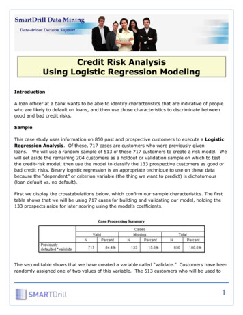
Published by :http://www.ijert.orgInternational Journal of Engineering Research & Technology (IJERT)ISSN: 2278-0181Vol. 6 Issue 07, July - 2017stress diagram at various loads which were applied to thecotter joint assembly.Fig 3: Assembly of cotter joint6. ANALYSIS OF COTTER JOINTThe finite element method (FEM) is a numericaltechnique for finding approximate solutions to boundaryvalue problems for partial differential equations. It is alsoreferred to as finite element analysis (FEA). It subdivides alarge problem into smaller, simpler parts that are calledfinite elements. The simple equations that model thesefinite elements are then assembled into a larger system ofequations that models the entire problem. FEM then usesvariation methods from the calculus of variations toapproximate a solution by minimizing an associated errorfunction. [1]The ANSYS program is self-contained generalpurpose finite component program developed andmaintained by Gloria May Josephine Svensson AnalysisSystems Iraqi National Congress. The program containsseveral routines, all reticulated and every one for mainpurpose of achieving a solution to an engineering drawbackby Finite component methodology. ANSYS provides anentire resolution to design issues. It consists of powerfuldesign capabilities like full constant quantity solidmodeling, design optimization and automotive vehiclemeshing, which provides engineers full management overtheir analysis.Analysis of cotter jointIn this paper the cotter joint is analyzed against thetensile force which is applied during the workingCondition.According to the solved problem we can applythe force P 50 KN on one of its end and other end isfixed. The material selected for cotter joint is plaincarbon steel of Grade 30C8 which is having(Syt 400N/mm2), so that cotter joint will fail above(Syt 400N/mm2).By the calculation, we found that maximum forceapplied is 50KN. By considering Factor of Safety weanalyzed the component at various load conditions i.e. at40KN, 50KN and 60KN.Static Structural AnalysisA static analysis calculates the effects of steadyloading conditions on a structure, while ignoring inertiaand damping effects, such as those caused by time-varyingloads. A static analysis can, however, include steady inertialoads (such as gravity and rotational velocity), and timevarying loads that can be approximated as static equivalentloads. The figure shows the deformation and von misesIJERTV6IS070202Fig 4: Project SchematicFig 5: Meshed AssemblyStructural analysis at 40 KNFig 6: Equivalent (von-mises) stress at 40kN loadwww.ijert.org(This work is licensed under a Creative Commons Attribution 4.0 International License.)340
Published by :http://www.ijert.orgInternational Journal of Engineering Research & Technology (IJERT)ISSN: 2278-0181Vol. 6 Issue 07, July - 2017Structural analysis at 60 KNFig 10: Equivalent (von-mises) stress at 60kN loadFig 7: Total deformation at 40KN loadStructural analysis at 50 KNFig 11: Total deformation at 60KN load7.Load(KN)405060Fig 8: Equivalent (von-mises) stress at 50kN loadFig 9: Total deformation at 50KN loadIJERTV6IS070202Max.Deformation (mm)0.029980.037310.04477RESULTVon-MisesStress (MPA)77.9897.47117RemarkSAFESAFESAFEThe maximum permissible value of stress ofstructural steel is 400 MPA. From this it is clear that thedesign of cotter joint is safe for 50kN as there is minimumacceptable deflection. The stress is also less than thepermissible stress of the material. Hence design of cotterjoint Assembly is safe.8. CONCLUSIONCotter joint is widely used in application inautomobiles and other field. So it should be strong enoughso if it can’t sustain that amount of load, otherwise there ispossibility of accidents. So we designed the cotter joint.Then by CATIA V5R20 we had done the modeling withgives correct design then design we are going to check byANSYS R15 to find stress in the cotter so we got perfectdesign of cotter joint.Based on the analysis results, following conclusionpoints are summarized, The maximum permissible value of stress of 30C8steel is 400 MPA. From the results achieved at loads 40kN, 50kNand 60kN it has given lower stress values anddeformation for the 30C8 steel.www.ijert.org(This work is licensed under a Creative Commons Attribution 4.0 International License.)341
Published by :http://www.ijert.orgInternational Journal of Engineering Research & Technology (IJERT)ISSN: 2278-0181Vol. 6 Issue 07, July - 20179. REFERENCES[1][2][3][4][5][6][7]Shaikh J, vanka H, [2015], “Modeling and analysis ofknuckle joint”, International journal & magazine ofengineering, Technology, Management and research , Vol. 2,Issue 11, Page no. 292-298Saxena N, Rajvaidya R, [2015],“Study and analysis ofknuckle joint with the replacement of material by usingTeflon”, Journal of engineering research & application, Vol.5, Issue 3, Page no. 67-71Xianguang KONG, Yuanying QIU [2012] , “Research andimplementation of CATIA tool integration technology basedon CAA."Dev dutt dwivedi, V.K. Jain [2016] ,“Design and analysisof automobile leaf spring using ansys." Vol. 3, Issue 1.Mahajan Vandana N, Shekhawat Sanjay P "Analysis ofblades of axial flow fan using ANSYS.""A text book of machine design."R.S khurmy & J.KGupta.“Design of machine element”, V.B Bhandari – 3rd edition.IJERTV6IS070202www.ijert.org(This work is licensed under a Creative Commons Attribution 4.0 International License.)342
the cotter joint is withstanding the load applied during the working condition or not. P So the methodology of the study includes 1. CAD Model of cotter joint using CATIAV5R20. 2. Design of cotter joint. 3. CAD Model of cotter joint assembly. 4. Meshing of cotter joint using ANSYS R15. 5. Elemental analysis at various loads. 6. Result and .