Transcription
Chapter 4: network layerchapter goals: understand principles behind network layerservices: network layer service modelsforwarding versus routinghow a router worksrouting (path selection)broadcast, multicastinstantiation, implementation in the InternetNetwork Layer 4-1Chapter 4: outline4.1 introduction4.2 virtual circuit anddatagram networks4.3 what’s inside a router4.4 IP: Internet Protocol datagram formatIPv4 addressingICMPIPv64.5 routing algorithms link state distance vector hierarchical routing4.6 routing in the Internet RIP OSPF BGP4.7 broadcast and multicastroutingNetwork Layer 4-21
Network layer applicationtransportnetworkdata linkphysicaltransport segment fromsending to receiving hoston sending sideencapsulates segmentsinto datagramson receiving side, deliverssegments to transportlayernetwork layer protocolsin every host, routerrouter examines headerfields in all IP datagramspassing through itnetworkdata linkphysicalnetworkdata linkphysicalnetworkdata linkphysicalnetworkdata linkphysicalnetworkdata linkphysicalnetworknetworkdata linkdata linkphysicalphysicalnetworkdata linkphysicalnetworkdata linkphysicalnetworkdata linkphysicalnetworkdata linkphysicalapplicationtransportnetworkdata linkphysicalNetwork Layer 4-3Two key network-layer functions forwarding: move packetsfrom router’s input toappropriate routeroutputrouting: determine routetaken by packets fromsource to dest. routing algorithmsanalogy: routing: process ofplanning trip fromsource to destforwarding: process ofgetting through singleinterchangeNetwork Layer 4-42
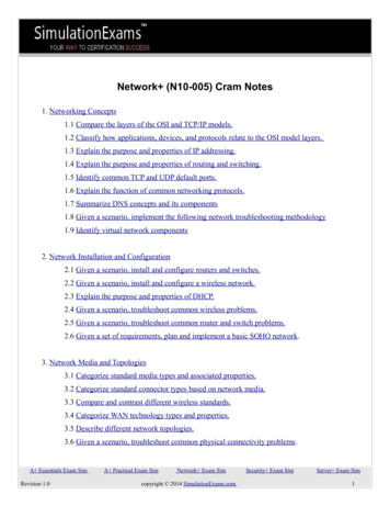
Interplay between routing and forwardingrouting algorithmrouting algorithm determinesend-end-path through networklocal forwarding tableheader value output linkforwarding table determineslocal forwarding at this router01000101011110013221value in arrivingpacket’s header101113 2Network Layer 4-5Connection setup 3rd important function in some networkarchitectures: ATM, frame relay, X.25 before datagrams flow, two end hosts andintervening routers establish virtual connection routers get involved network vs transport layer connection service: network: between two hosts (may also involve interveningrouters in case of VCs) transport: between two processesNetwork Layer 4-63
Network service modelQ: What service model for “channel” transportingdatagrams from sender to receiver?example services forindividual datagrams: guaranteed deliveryguaranteed delivery withless than 40 msec delayexample services for a flowof datagrams: in-order datagramdeliveryguaranteed minimumbandwidth to flowrestrictions on changes ininter-packet spacingNetwork Layer 4-7Network layer service antees ?CongestionBandwidth Loss Order Timing feedbackbest effort oyesnono (inferredvia loss)nocongestionnocongestionyesnoyesnonoNetwork Layer 4-84
Chapter 4: outline4.1 introduction4.2 virtual circuit anddatagram networks4.3 what’s inside a router4.4 IP: Internet Protocol datagram formatIPv4 addressingICMPIPv64.5 routing algorithms link state distance vector hierarchical routing4.6 routing in the Internet RIP OSPF BGP4.7 broadcast and multicastroutingNetwork Layer 4-9Connection, connection-less service datagram network provides network-layerconnectionless servicevirtual-circuit network provides network-layerconnection serviceanalogous to TCP/UDP connecton-oriented /connectionless transport-layer services, but: service: host-to-host no choice: network provides one or the other implementation: in network coreNetwork Layer 4-105
Virtual circuits“source-to-dest path behaves much like telephonecircuit” performance-wise network actions along source-to-dest path call setup, teardown for each call before data can floweach packet carries VC identifier (not destination hostaddress)every router on source-dest path maintains “state” foreach passing connectionlink, router resources (bandwidth, buffers) may beallocated to VC (dedicated resources predictableservice)Network Layer 4-11VC implementationa VC consists of:1. path from source to destination2. VC numbers, one number for each link along path3. entries in forwarding tables in routers along path packet belonging to VC carries VC number(rather than dest address)VC number can be changed on each link. new VC number comes from forwarding tableNetwork Layer 4-126
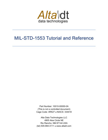
VC forwarding table22121VC numberinterfacenumberforwarding table innorthwest router:Incoming interface1231 Incoming VC #1263797 2323Outgoing interfaceOutgoing VC #312322181787 VC routers maintain connection state information!Network Layer 4-13Virtual circuits: signaling protocols used to setup, maintain teardown VCused in ATM, frame-relay, X.25not used in today’s Internetapplication5. data flow beginstransport4.call connectednetwork1.initiate calldata linkphysicalapplicationtransport3. accept callnetwork2. incoming calldata linkphysical6. receive dataNetwork Layer 4-147
Datagram networks no call setup at network layerrouters: no state about end-to-end connections no network-level concept of “connection” packets forwarded using destination host addressapplicationtransportnetwork 1. send datagramsdata linkphysicalapplicationtransport2. receive datagrams networkdata linkphysicalNetwork Layer 4-15Datagram forwarding tablerouting algorithmlocal forwarding tabledest address output linkaddress-range 1address-range 2address-range 3address-range 44 billion IP addresses, sorather than list individualdestination addresslist range of addresses(aggregate table entries)3221IP destination address inarriving packet’s header13 2Network Layer 4-168
Datagram forwarding tableDestination Address RangeLink Interface11001000 00010111 00010000 00000000through11001000 00010111 00010111 11111111011001000 00010111 00011000 00000000through11001000 00010111 00011000 11111111111001000 00010111 00011001 00000000through11001000 00010111 00011111 111111112otherwise3Q: but what happens if ranges don’t divide up so nicely?Network Layer 4-17Longest prefix matchinglongest prefix matchingwhen looking for forwarding table entry for givendestination address, use longest address prefix thatmatches destination address.Destination Address RangeLink interface11001000 00010111 00010*** *********011001000 00010111 00011000 *********111001000 00010111 00011*** *********2otherwise3examples:DA: 11001000 00010111 00010110 10100001DA: 11001000 00010111 00011000 10101010which interface?which interface?Network Layer 4-189
Datagram or VC network: why?ATM (VC)Internet (datagram) data exchange amongcomputers strict timing, reliabilityrequirements need for guaranteed service “elastic” service, no stricttiming req. many link types different characteristics uniform service difficult evolved from telephonyhuman conversation:“dumb” end systems telephones complexity insidenetwork“smart” end systems(computers) can adapt, perform control,error recovery simple inside network,complexity at “edge”Network Layer 4-19Chapter 4: outline4.1 introduction4.2 virtual circuit anddatagram networks4.3 what’s inside a router4.4 IP: Internet Protocol datagram formatIPv4 addressingICMPIPv64.5 routing algorithms link state distance vector hierarchical routing4.6 routing in the Internet RIP OSPF BGP4.7 broadcast and multicastroutingNetwork Layer 4-2010
Router architecture overviewtwo key router functions: run routing algorithms/protocol (RIP, OSPF, BGP)forwarding datagrams from incoming to outgoing linkswitchingfabricrouter input portsroutingprocessorrouter output portsNetwork Layer 4-21Input port lookup,forwardingswitchfabricqueueingphysical layer:bit-level receptiondata link layer:e.g., Ethernetsee chapter 5decentralized switching: given datagram dest., lookup output portusing forwarding table in input portmemorygoal: complete input port processing at‘line speed’queuing: if datagrams arrive faster thanforwarding rate into switch fabricNetwork Layer 4-2211
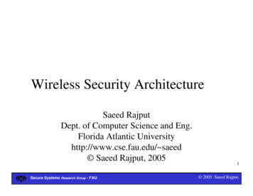
Switching fabrics transfer packet from input buffer to appropriateoutput bufferswitching rate: rate at which packets can betransfer from inputs to outputs often measured as multiple of input/output line rate N inputs: switching rate N times line rate desirable three types of switching fabricsmemorybusmemorycrossbarNetwork Layer 4-23Switching via memoryfirst generation routers: traditionalcomputers with switching under direct controlof CPU packet copied to system’s memory speed limited by memory bandwidth (2 bus crossings rt(e.g.,Ethernet)system busNetwork Layer 4-2412
Switching via a bus datagram from input port memoryto output port memory via ashared busbus contention: switching speedlimited by bus bandwidth32 Gbps bus, Cisco 5600: sufficientspeed for access and enterpriseroutersbusNetwork Layer 4-25Switching via interconnection network overcome bus bandwidth limitationsbanyan networks, crossbar, otherinterconnection nets initiallydeveloped to connect processors inmultiprocessoradvanced design: fragmentingdatagram into fixed length cells,switch cells through the fabric.Cisco 12000: switches 60 Gbpsthrough the interconnectionnetworkcrossbarNetwork Layer 4-2613
Output portsswitchfabricdatagrambufferqueueing linklayerprotocol(send)lineterminationbuffering required when datagrams arrive fromfabric faster than the transmission ratescheduling discipline chooses among queueddatagrams for transmissionNetwork Layer 4-27Output port queueingswitchfabricat t, packets morefrom input to output switchfabricone packet time laterbuffering when arrival rate via switch exceedsoutput line speedqueueing (delay) and loss due to output port bufferoverflow!Network Layer 4-2814
How much buffering? RFC 3439 rule of thumb: average buffering equalto “typical” RTT (say 250 msec) times linkcapacity C e.g., C 10 Gpbs link: 2.5 Gbit buffer recent recommendation: with N flows, bufferingequal toRTT . CNNetwork Layer 4-29Input port queuing fabric slower than input ports combined - queueing mayoccur at input queues queueing delay and loss due to input buffer overflow!Head-of-the-Line (HOL) blocking: queued datagram at frontof queue prevents others in queue from moving forwardswitchfabricoutput port contention:only one red datagram can betransferred.lower red packet is blockedswitchfabricone packet timelater: green packetexperiences HOLblockingNetwork Layer 4-3015
Chapter 4: outline4.1 introduction4.2 virtual circuit anddatagram networks4.3 what’s inside a router4.4 IP: Internet Protocol datagram formatIPv4 addressingICMPIPv64.5 routing algorithms link state distance vector hierarchical routing4.6 routing in the Internet RIP OSPF BGP4.7 broadcast and multicastroutingNetwork Layer 4-31The Internet network layerhost, router network layer functions:transport layer: TCP, UDPIP protocolrouting protocolsnetworklayer addressing conventions datagram format packet handling conventions path selection RIP, OSPF, BGPforwardingtableICMP protocol error reporting router “signaling”link layerphysical layerNetwork Layer 4-3216
IP datagram formatIP protocol versionnumberheader length(bytes)“type” of datamax numberremaining hops(decremented ateach router)upper layer protocolto deliver payload to32 bitsver head. type oflen service16-bit identifieruppertime tolayerlivetotal datagramlength agmentation/reassembly32 bit source IP address32 bit destination IP addresshow much overhead? 20 bytes of TCP 20 bytes of IP 40 bytes applayer overheade.g. timestamp,record routetaken, specifylist of routersto visit.options (if any)data(variable length,typically a TCPor UDP segment)Network Layer 4-33IP fragmentation, reassembly fragmentation:in: one large datagramout: 3 smaller datagrams reassembly network links have MTU(max.transfer size) largest possible link-levelframe different link types,different MTUslarge IP datagram divided(“fragmented”) within net one datagram becomesseveral datagrams “reassembled” only atfinal destination IP header bits used toidentify, order relatedfragmentsNetwork Layer 4-3417
IP fragmentation, reassemblyexample: 4000 byte datagramMTU 1500 bytes1480 bytes indata fieldoffset 1480/8length ID fragflag 4000 x 0offset 0one large datagram becomesseveral smaller datagramslength ID fragflag 1500 x 1offset 0length ID fragflag 1500 x 1offset 185length ID fragflag 1040 x 0offset 370Network Layer 4-35Chapter 4: outline4.1 introduction4.2 virtual circuit anddatagram networks4.3 what’s inside a router4.4 IP: Internet Protocol datagram formatIPv4 addressingICMPIPv64.5 routing algorithms link state distance vector hierarchical routing4.6 routing in the Internet RIP OSPF BGP4.7 broadcast and multicastroutingNetwork Layer 4-3618
IP addressing: introduction IP address: 32-bitidentifier for host,router interfaceinterface: connectionbetween host/routerand physical link router’s typically havemultiple interfaces host typically has oneinterface IP addresses associatedwith each 223.1.1.1 11011111 00000001 00000001 00000001223111Network Layer 4-37Subnets IPaddress: subnet part - high orderbits host part - low orderbits what’sa subnet ? device interfaces withsame subnet part of IPaddress can physically reacheach other withoutintervening 3.2network consisting of 3 subnetsNetwork Layer 4-3819
Subnets223.1.1.0/24recipe to determine thesubnets, detach eachinterface from itshost or router,creating islands ofisolated networks each isolated networkis called a .1.3.2223.1.3.1223.1.3.0/24subnet mask: /24Network Layer 4-39Subnets223.1.1.2how .2.1223.1.3.27223.1.2.2223.1.3.1223.1.3.2Network Layer 4-4020
IP addressing: CIDRCIDR: Classless InterDomain Routing subnet portion of address of arbitrary length address format: a.b.c.d/x, where x is # bits insubnet portion of addresssubnetparthostpart11001000 00010111 00010000 00000000200.23.16.0/23Network Layer 4-41IP addresses: how to get one?Q: How does a host get IP address? hard-coded by system admin in a file Windows: control-panel- network- configuration- tcp/ip- properties UNIX: /etc/rc.config DHCP: Dynamic Host Configuration Protocol:dynamically get address from as server “plug-and-play”Network Layer 4-4221
DHCP: Dynamic Host Configuration Protocolgoal: allow host to dynamically obtain its IP address from networkserver when it joins network can renew its lease on address in use allows reuse of addresses (only hold address whileconnected/“on”) support for mobile users who want to join network (moreshortly)DHCP overview: host broadcasts “DHCP discover” msg [optional]DHCP server responds with “DHCP offer” msg [optional]host requests IP address: “DHCP request” msgDHCP server sends address: “DHCP ack” msgNetwork Layer 4-43DHCP client-server 2.2arriving DHCPclient needsaddress in /24Network Layer 4-4422
DHCP client-server scenarioDHCP server: 223.1.2.5DHCP discoversrc : 0.0.0.0, 68dest.: 255.255.255.255,67yiaddr: 0.0.0.0transaction ID: 654arrivingclientDHCP offersrc: 223.1.2.5, 67dest: 255.255.255.255, 68yiaddrr: 223.1.2.4transaction ID: 654lifetime: 3600 secsDHCP requestsrc: 0.0.0.0, 68dest:: 255.255.255.255, 67yiaddrr: 223.1.2.4transaction ID: 655lifetime: 3600 secsDHCP ACKsrc: 223.1.2.5, 67dest: 255.255.255.255, 68yiaddrr: 223.1.2.4transaction ID: 655lifetime: 3600 secsNetwork Layer 4-45DHCP: more than IP addressesDHCP can return more than just allocated IPaddress on subnet: address of first-hop router for client name and IP address of DNS sever network mask (indicating network versus host portionof address)Network Layer 4-4623
DHCP: exampleDHCPUDPIPEthPhyDHCPDHCPDHCPDHCP DHCP DHCPUDPIPEthPhyDHCPDHCPDHCPDHCP168.1.1.1router with DHCPserver built intorouter connecting laptop needsits IP address, addr offirst-hop router, addr ofDNS server: use DHCPDHCP request encapsulatedin UDP, encapsulated in IP,encapsulated in 802.1EthernetEthernet frame broadcast(dest: FFFFFFFFFFFF) on LAN,received at router runningDHCP serverEthernet demuxed to IPdemuxed, UDP demuxed toDHCPNetwork Layer 4-47DHCP: example PDHCPUDPIPEthPhy router with DHCPserver built intorouter DCP server formulatesDHCP ACK containingclient’s IP address, IPaddress of first-hoprouter for client, name& IP address of DNSserverencapsulation of DHCPserver, frame forwardedto client, demuxing up toDHCP at clientclient now knows its IPaddress, name and IPaddress of DSN server,IP address of its first-hop routerNetwork Layer 4-4824
DHCP: Wiresharkoutput (homeLAN)Message type: Boot Request (1)Hardware type: EthernetHardware address length: 6Hops: 0Transaction ID: 0x6b3a11b7Seconds elapsed: 0Bootp flags: 0x0000 (Unicast)Client IP address: 0.0.0.0 (0.0.0.0)Your (client) IP address: 0.0.0.0 (0.0.0.0)Next server IP address: 0.0.0.0 (0.0.0.0)Relay agent IP address: 0.0.0.0 (0.0.0.0)Client MAC address: Wistron 23:68:8a (00:16:d3:23:68:8a)Server host name not givenBoot file name not givenMagic cookie: (OK)Option: (t 53,l 1) DHCP Message Type DHCP RequestOption: (61) Client identifierLength: 7; Value: 010016D323688A;Hardware type: EthernetClient MAC address: Wistron 23:68:8a (00:16:d3:23:68:8a)Option: (t 50,l 4) Requested IP Address 192.168.1.101Option: (t 12,l 5) Host Name "nomad"Option: (55) Parameter Request ListLength: 11; Value: 010F03062C2E2F1F21F92B1 Subnet Mask; 15 Domain Name3 Router; 6 Domain Name Server44 NetBIOS over TCP/IP Name Server requestMessage type: Boot Reply (2)Hardware type: EthernetHardware address length: 6Hops: 0Transaction ID: 0x6b3a11b7Seconds elapsed: 0Bootp flags: 0x0000 (Unicast)Client IP address: 192.168.1.101 (192.168.1.101)Your (client) IP address: 0.0.0.0 (0.0.0.0)Next server IP address: 192.168.1.1 (192.168.1.1)Relay agent IP address: 0.0.0.0 (0.0.0.0)Client MAC address: Wistron 23:68:8a (00:16:d3:23:68:8a)Server host name not givenBoot file name not givenMagic cookie: (OK)Option: (t 53,l 1) DHCP Message Type DHCP ACKOption: (t 54,l 4) Server Identifier 192.168.1.1Option: (t 1,l 4) Subnet Mask 255.255.255.0Option: (t 3,l 4) Router 192.168.1.1Option: (6) Domain Name ServerLength: 12; Value: 445747E2445749F244574092;IP Address: 68.87.71.226;IP Address: 68.87.73.242;IP Address: 68.87.64.146Option: (t 15,l 20) Domain Name "hsd1.ma.comcast.net."replyNetwork Layer 4-49IP addresses: how to get one?Q: how does network get subnet part of IP addr?A: gets allocated portion of its provider ISP’s addressspaceISP's block11001000 00010111 00010000 00000000200.23.16.0/20Organization 0Organization 1Organization 2.11001000 00010111 00010000 0000000011001000 00010111 00010010 0000000011001000 00010111 00010100 00000000 . .200.23.16.0/23200.23.18.0/23200.23.20.0/23 .Organization 711001000 00010111 00011110 00000000200.23.30.0/23Network Layer 4-5025
Hierarchical addressing: route aggregationhierarchical addressing allows efficient advertisement of routinginformation:Organization 0200.23.16.0/23Organization 1200.23.18.0/23Organization 2200.23.20.0/23Organization 7.Fly-By-Night-ISP“Send me anythingwith 30.0/23ISPs-R-Us“Send me anythingwith addressesbeginning199.31.0.0/16”Network Layer 4-51Hierarchical addressing: more specific routesISPs-R-Us has a more specific route to Organization 1Organization 0200.23.16.0/23Organization 2200.23.20.0/23Organization 7.Fly-By-Night-ISP“Send me anythingwith 30.0/23ISPs-R-UsOrganization 1200.23.18.0/23“Send me anythingwith addressesbeginning 199.31.0.0/16or 200.23.18.0/23”Network Layer 4-5226
IP addressing: the last word.Q: how does an ISP get block of addresses?A: ICANN: Internet Corporation for AssignedNames and Numbers http://www.icann.org/ allocates addresses manages DNS assigns domain names, resolves disputesNetwork Layer 4-53NAT: network address translationrest ofInternetlocal network(e.g., home .710.0.0.3all datagrams leaving localnetwork have same singlesource NAT IP address:138.76.29.7,differentsource port numbersdatagrams with source ordestination in this networkhave 10.0.0/24 address forsource, destination (as usual)Network Layer 4-5427
NAT: network address translationmotivation: local network uses just one IP address as faras outside world is concerned: range of addresses not needed from ISP: just oneIP address for all devices can change addresses of devices in local networkwithout notifying outside world can change ISP without changing addresses ofdevices in local network devices inside local net not explicitly addressable,visible by outside world (a security plus)Network Layer 4-55NAT: network address translationimplementation: NAT router must: outgoing datagrams: replace (source IP address, port #) ofevery outgoing datagram to (NAT IP address, new port #). . . remote clients/servers will respond using (NAT IPaddress, new port #) as destination addr remember (in NAT translation table) every (source IP address,port #) to (NAT IP address, new port #) translation pair incoming datagrams: replace (NAT IP address, new port #) indest fields of every incoming datagram with corresponding(source IP address, port #) stored in NAT tableNetwork Layer 4-5628
NAT: network address translation2: NAT routerchanges datagramsource addr from10.0.0.1, 3345 to138.76.29.7, 5001,updates tableNAT translation tableWAN side addrLAN side addr1: host 10.0.0.1sends datagram to128.119.40.186, 80138.76.29.7, 5001 10.0.0.1, 3345 S: 10.0.0.1, 3345D: 128.119.40.186, 8010.0.0.112S: 138.76.29.7, 5001D: 128.119.40.186, 80138.76.29.7S: 128.119.40.186, 80D: 138.76.29.7, 50013: reply arrivesdest. address:138.76.29.7, 5001310.0.0.4S: 128.119.40.186, 80D: 10.0.0.1, 334510.0.0.2410.0.0.34: NAT routerchanges datagramdest addr from138.76.29.7, 5001 to 10.0.0.1, 3345Network Layer 4-57NAT: network address translation 16-bit port-number field: 60,000 simultaneous connections with a singleLAN-side address!NAT is controversial: routers should only process up to layer 3 violates end-to-end argument NAT possibility must be taken into account by appdesigners, e.g., P2P applications address shortage should instead be solved byIPv6Network Layer 4-5829
NAT traversal problem client wants to connect toserver with address 10.0.0.1 server address 10.0.0.1 local toLAN (client can’t use it asdestination addr) only one externally visible NATedaddress: 138.76.29.7 solution1: statically configureNAT to forward incomingconnection requests at givenport to serverclient10.0.0.1?10.0.0.4138.76.29.7NATrouter e.g., (123.76.29.7, port 2500)always forwarded to 10.0.0.1 port25000Network Layer 4-59NAT traversal problem solution 2: Universal Plug and Play(UPnP) Internet Gateway Device(IGD) Protocol. Allows NATedhost to: learn public IP address(138.76.29.7) add/remove port mappings(with lease times)10.0.0.1IGDNATrouteri.e., automate static NAT portmap configurationNetwork Layer 4-6030
NAT traversal problem solution 3: relaying (used in Skype) NATed client establishes connection to relay external client connects to relay relay bridges packets between to connections2. connection torelay initiatedby client1. connection torelay initiatedby NATed host3. terNetwork Layer 4-61Chapter 4: outline4.1 introduction4.2 virtual circuit anddatagram networks4.3 what’s inside a router4.4 IP: Internet Protocol datagram formatIPv4 addressingICMPIPv64.5 routing algorithms link state distance vector hierarchical routing4.6 routing in the Internet RIP OSPF BGP4.7 broadcast and multicastroutingNetwork Layer 4-6231
ICMP: internet control message protocol used by hosts & routersto communicatenetwork-levelinformation error reporting:unreachable host, network,port, protocol echo request/reply (used byping) network-layer “above” IP: ICMP msgs carried in IPdatagrams ICMP message: type, codeplus first 8 bytes of IPdatagram causing ionecho reply (ping)dest. network unreachabledest host unreachabledest protocol unreachabledest port unreachabledest network unknowndest host unknownsource quench (congestioncontrol - not used)echo request (ping)route advertisementrouter discoveryTTL expiredbad IP headerNetwork Layer 4-63Traceroute and ICMP source sends series ofUDP segments to dest first set has TTL 1 second set has TTL 2, etc. unlikely port number when nth set of datagramsarrives to nth router: router discards datagrams and sends source ICMPmessages (type 11, code 0) ICMP messages includesname of router & IPaddress3 probes when ICMP messagesarrives, source recordsRTTsstopping criteria: UDP segment eventuallyarrives at destinationhost destination returns ICMP“port unreachable”message (type 3, code 3) source stops3 probes3 probesNetwork Layer 4-6432
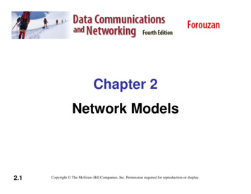
IPv6: motivation initial motivation: 32-bit address space soon to becompletely allocated.additional motivation: header format helps speed processing/forwarding header changes to facilitate QoSIPv6 datagram format: fixed-length 40 byte header no fragmentation allowedNetwork Layer 4-65IPv6 datagram formatpriority: identify priority among datagrams in flowflow Label: identify datagrams in same “flow.”(concept of“flow” not well defined).next header: identify upper layer protocol for dataverpriflow labelhop limitpayload lennext hdrsource address(128 bits)destination address(128 bits)data32 bitsNetwork Layer 4-6633
Other changes from IPv4 checksum: removed entirely to reduce processingtime at each hopoptions: allowed, but outside of header, indicatedby “Next Header” fieldICMPv6: new version of ICMP additional message types, e.g. “Packet Too Big” multicast group management functionsNetwork Layer 4-67Transition from IPv4 to IPv6 not all routers can be upgraded simultaneously no “flag days” how will network operate with mixed IPv4 andIPv6 routers?tunneling: IPv6 datagram carried as payload in IPv4datagram among IPv4 routersIPv4 header fieldsIPv4 source, dest addrIPv6 header fieldsIPv6 source dest addrIPv4 payloadUDP/TCP payloadIPv6 datagramIPv4 datagramNetwork Layer 4-6834
TunnelingIPv4 tunnelconnecting IPv6 routersABIPv6IPv6ABCIPv6IPv6IPv4logical view:physical view:EFIPv6IPv6DEFIPv4IPv6IPv6Network Layer 4-69TunnelingIPv4 tunnelconnecting IPv6 routersABIPv6IPv6ABCIPv6IPv6IPv4logical view:physical view:flow: Xsrc: Adest: : Esrc:Bdest: EFlow: XSrc: ADest: FFlow: XSrc: ADest: FdatadataB-to-C:IPv6 insideIPv4B-to-C:IPv6 insideIPv4flow: Xsrc: Adest: FdataE-to-F:IPv6Network Layer 4-7035
Chapter 4: outline4.1 introduction4.2 virtual circuit anddatagram networks4.3 what’s inside a router4.4 IP: Internet Protocol 4.5 routing algorithms link state distance vector hierarchical routing4.6 routing in the Internet RIP OSPF BGPdatagram formatIPv4 addressingICMPIPv64.7 broadcast and multicastroutingNetwork Layer 4-71Interplay between routing, forwardingrouting algorithm determinesend-end-path through networkrouting algorithmlocal forwarding tabledest address output linkaddress-range 1address-range 2address-range 3address-range 4forwarding table determineslocal forwarding at this router3221IP destination address inarriving packet’s header13 2Network Layer 4-7236
Graph abstraction5v2u21xgraph: G (N,E)3w315z1y2N set of routers { u, v, w, x, y, z }E set of links { (u,v), (u,x), (v,x), (v,w), (x,w), (x,y), (w,y), (w,z), (y,z) }aside: graph abstraction is useful in other network contexts, e.g.,P2P, where N is set of peers and E is set of TCP connectionsNetwork Layer 4-73Graph abstraction: costs52uv21x3w31c(x,x’) cost of link (x,x’)e.g., c(w,z) 55z1y2cost could always be 1, orinversely related to bandwidth,or inversely related tocongestioncost of path (x1, x2, x3, , xp) c(x1,x2) c(x2,x3) c(xp-1,xp)key question: what is the least-cost path between u and z ?routing algorithm: algorithm that finds that least cost pathNetwork Layer 4-7437
Routing algorithm classificationQ: static or dynamic?Q: global or decentralizedinformation?static: routes change slowly overtimedynamic: routes change morequickly periodic update in response to linkcost changesglobal: all routers have completetopology, link cost info “link state” algorithmsdecentralized: router knows physically-connected neighbors, linkcosts to neighbors iterative process ofcomputation, exchange ofinfo with neighbors “distance vector” algorithmsNetwork Layer 4-75Chapter 4: outline4.1 introduction4.2 virtual circuit anddatagram networks4.3 what’s inside a router4.4 IP: Internet Protocol datagram formatIPv4 addressingICMPIPv64.5 routing algorithms link state distance vector hierarchical routing4.6 routing in the Internet RIP OSPF BGP4.7 broadcast and multicastroutingNetwork Layer 4-7638
A Link-State Routing AlgorithmDijkstra’s algorithm net topology, link costsknown to all nodes accomplished via “link statebroadcast” all nodes have same info computes least cost pathsfrom one node (‘source”)to all other nodes gives forwarding table forthat node notation: c(x,y): link cost fromiterative: aft
memory memory bus crossbar Network Layer 4-24 Switching via memory first generation routers: traditional computers with switching under direct control of CPU packet copied to system's memory speed limited by memory bandwidth (2 bus crossings per datagram) input port (e.g., Ethernet) memory output port (e.g., Ethernet) system bus