Transcription
Tutorial Guide toAutoCAD 2022 2D Drawing, 3D ModelingShawna LockhartSDCP U B L I C AT I O N SBetter Textbooks. Lower Prices.www.SDCpublications.comFor Microsoft Windows
Visit the following websites to learn more about this book:Powered by TCPDF (www.tcpdf.org)
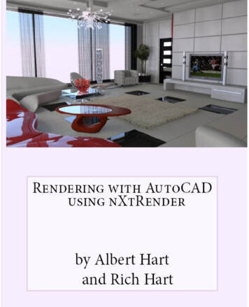
INTRODUCTION 57BASIC CONSTRUCTION TECHNIQUESIntroductionYou usually create drawings by combining and modifying several differ ent basic primitive shapes, such as lines, circles, and arcs, to create morecomplex shapes. This tutorial will help you learn how to draw shapes.Keep in mind that one of the advantages of using CAD over drawingon paper is that you are creating an accurate model of the drawinggeometry. In Tutorial 3, you will learn to list information from the draw ing database. Information extracted from the drawing is accurate only ifyou create the drawing accurately in the first place.2ObjectivesWhen you have com pleted this tutorial, youwill be able to1. Open existingdrawings.2. Work with new andexisting layers.StartingBefore you begin, launch AutoCAD 2022.Opening an Existing DrawingThis tutorial shows you how to add arcs and circles to the subdivisiondrawing provided with the datafiles that came with this guide. In Tuto rial 3 you will finish the subdivision drawing so that the final drawingwill look like Figure 2.1.3. Draw, using the Arcand Circle commands.4. Set and use runningObject snaps.5. Change the display,using Zoom and Pan.6. Use Dynamic View.7. Draw ellipses.A SUBDIVISION LOCATED IN THE NE1/4 OF THE NE 1/4 OF SEC. 14,T.1S, R.5E, M.P.MA 15’ UTILITY EASEMENT ISRESERVED ALONG ALL EXTERIORLOT LINES.BRONWYNECSNROADGAPONDET2RRADY ROTAS110CIRCLE3456789Wannabe Heights EstatesFigure 2.1To open an existing drawing, use the Application icon, Open selectionor click the button that looks like an open folder from the Quick Accesstoolbar.Click: Open buttonThe Select File dialog box appears on your screen. Use the center por tion, which shows the default directory and drive, to select the locationwhere your datafiles have been stored. You should have already createda folder called datafiles, and copied all the datafiles for this book intoit. If you have not done so, you may want to review the Getting StartedTip: It is easy to download thedatafiles. Use your browser tonavigate to www.sdcpublications.com/Authors/ShawnaLockhart. From there select thetext you are using. Find andclick the Download button onthe page for your text.
58 Tutorial 2 BASIC CONSTRUCTION TECHNIQUESTip: Use the buttons at the leftof the dialog box to show theHistory (recently used files), MyDocuments folder contents, orFavorites you have added. Toadd a favorite, find the folderand then right-click the Favorites button. Pick Add CurrentFolder from the pop-up menuthat appears. To add a folderas a button, pick Tools, AddCurrent Folder to Places.You can also use Autodesk 360to display documents you havestored on a remote internetserver sometimes called “thecloud.” This allows you to viewyour files from anyplace youcan connect to the internet. Youcan also browse your computer’s desktop and Autodesk’sBuzzsaw area from these sidebar icons.chapters. If the correct folder is not showing in the Look In box, use theUp One Level icon or expand the choices by clicking on the downwardarrow for the Look In box. Use the scroll bars if necessary to scrolldown the list of directories and open the appropriate one so the filesappear in the dialog box as in Figure 2.2. Scroll down the list of filesuntil you see the file named subdivis.dwg. When you select a file, apreview of the file appears in the box to the right. (Older files may notshow a preview.)Figure 2.2Menu choices at the top right of the Select File dialog box let you selectdifferent views to be displayed in the file list and other useful tools, suchas a Find selection to search for files.Click: Tools, FindType: subdivis (in the Named area)Click: Find Now button (from upper right of dialog box)The Find dialog box displays the location for the file named Subdivis.dwg, as shown in Figure 2.3. You can type in a portion of the name tomatch if you cannot remember the entire name or click the Date Modi fied tab if you want to search by date and time the file was created.Figure 2.3
SAVING AS A NEW FILE 59Double-click: Subdivis.dwg ( to select it from the list at the bottom)You return to the Select File dialog box.Click: OpenDouble-click: in the center of the screen to zoom to the drawing extentsWhen you have opened the file, it appears on your screen, as shownin Figure 2.4. It opens with its own defaults for Grid, Snap, and otherfeatures. These settings are saved in the drawing file.Figure 2.4Saving as a New FileThe Save As command allows you to save your drawing to a new filename and/or different drive or folder. You can select this commandfrom the Application icon or from the Quick Access toolbar.Click: Save As buttonThe Save Drawing As dialog box appears similar to Figure 2.5.Figure 2.5Tip: Don’t use the Save command because that will saveyour changes into the originaldatafile.
60 Tutorial 2 BASIC CONSTRUCTION TECHNIQUESTip: Notice that if you haveset up an account, you canuse the OneDrive selection tosave your files to storage in the“cloud.”Warning: If you save a file withthe same name as one alreadyin the directory, you will see amessage the file “already exists. Do you want to replace it?”Choose No unless you want toreplace the file.On your own, select the drive and folder work and specify the name for yourdrawing, subdivis.dwg.In this case, the new file name is the same as the previous file name, butthe folder is different. This creates a new copy of drawing subdivis.dwgsaved in the folder named work.The original subdivis.dwg remains unchanged on your drive. When youuse the Save As command and specify a new file name, the software setsthe newly saved file as current.Using LayersYou can organize drawing information on different layers. Think of alayer as a transparent drawing sheet that you place over the drawingand that you can remove at will. The coordinate system remains thesame from one layer to another, so graphical objects on separate layersremain aligned. You can create a virtually unlimited number of layerswithin the same drawing. The Layer command allows control of thecolor and linetype associated with a given layer. Using layers allows youto overlay a base drawing with several different levels of detail (such aswiring or plumbing schematics over the base plan for a building).By using layers, you can also control which portions of a drawing areplotted, or remove dimensions or text from a drawing to make it easierto add or change objects. You can also lock layers, making them inac cessible but still visible on the screen. You can’t change anything on alocked layer until you unlock it.Current LayerThe current layer is the layer you are working on. Any new objects youdraw are added to the current layer. The default current layer is layer 0.If you do not create and use other layers, your drawing will be createdon layer 0. You used this layer when drawing the plot plan in Tutorial 1.Layer 0 is a special layer provided in the AutoCAD program.You cannot rename or delete layer 0 from the list of layers. Layer 0has special properties when used with the Block and Insert commands,which are covered in Tutorial 10.Layer POINTS is the current layer in mysubdivis.dwg. There can beonly one current layer at a time. The name of the current layer appearson the Layer toolbar.Controlling LayersThe Layer Control feature on the Layers panel on the Home tab of theribbon is an easy way to control the visibility of existing layers in yourdrawing. You will learn more about creating and using layers in this tuto rial. For now, you will use layers that have already been created for you.Click: on layer name POINTS from the Layers panelThe list of available layers pulls down, as shown in Figure 2.6. Noticethe special layer 0 displayed near the top of the list.
CONTROLLING COLORS 61Figure 2.6Click: on the layer name CENTERLINE from the Layer Control listIt becomes the current layer shown on the toolbar. Any new objects willbe created on this layer until you select a different current layer. TheLayer Control now should look like Figure 2.7, showing the layer nameCENTERLINE.Figure 2.7Use the Line command you learned in Tutorial 1 to draw a line off to the side ofthe subdivision drawing.Note that it is green and has a centerline linetype (long dash, shortdash, long dash). The line you drew is on Layer CENTERLINE.Erase or Undo the line on your own.Controlling ColorsEach layer has a color associated with it. Using different colors for dif ferent layers helps you visually distinguish different information in thedrawing. An object’s color also may control appearance during printing.There are two different ways of selecting the color for objects onyour screen. The best way is usually to set the layer color and drawthe objects on the appropriate layer. This method keeps your drawingorganized. The other method is to use the Color Control feature on theProperties panel. To select the Color Control pull-down feature,Click: ByLayer from the Properties panel to pull down the Color ControlClick to expandcolor choicesFigure 2.8Note that the standard colors (yellow, red, green, blue, etc.) are shown.You can also choose More Colors to view the full color palette.Tip: If your panels areminimized, you may need toclick Properties to expand thepanel (see Figure 2.8).
62 Tutorial 2 BASIC CONSTRUCTION TECHNIQUESClick: More ColorsTip: On a black background,color 7 used for layer 0 appearsas white; on a white background it appears black.The Select Color dialog box shown in Figure 2.9 appears on yourscreen, giving you a full range of colors from which to choose.Figure 2.9The three tabs of the Select Color dialog box allow you to chooseamong different methods to determine the color for your drawingentities. The True Color tab allows you to set color to either RGB, whichstands for Red, Green, Blue, the primary colors of light, or HSL, whichstands for the Hue, Saturation, and Luminance of the color. The ColorBooks tab lets you select from among different standard ink manufac turer’s predefined colors so that you can match print colors very closelyto the colors you choose on your screen. In this text you will use IndexColor (AutoCAD Color Index) as the method for selecting color.Make sure the Index Color tab is selected.The default option for the Color (and also for the Linetype) commandis BYLAYER. It’s the best selection because, when you draw a line,the color and linetype will be those of the current layer. Otherwise, thecolor in your drawing can become very confusing. You will click Cancelto exit the Select Color dialog box without making any changes. Thecolors for your new objects will continue to be determined by the layeron which they are created. Layers can have associated linetypes, as wellas colors, as Layer CENTERLINE does.Click: CancelLayer VisibilityOne of the advantages of using layers in the drawing is that you canchoose not to display selected layers. That way, if you want to createprojection lines or even notes about the drawing, you can draw them ona layer that you will later turn off, so that it isn’t displayed or printed.Or you may want to create a complex drawing with many layers, suchas a building plan that contains the electrical plan on one layer and the
FREEZING LAYERS 63mechanical plan on another, along with separate layers for the walls,windows, and so on. You can store all the information in a single draw ing, and then plot different combinations of layers to create the electri cal layout, first-floor plan, and any other combination you want.Next you will use the Layer Control to lock, freeze, and turn off some ofthe layers in this drawing.Click: on CENTERLINE to show the list of layersThe list of layers pulls down. Refer to Figure 2.10 as you make thefollowing selections.Click: the On/Off icon, which looks like a lightbulb, to the left ofLayer EXISTING ROADClick: any blank area of the screen away from the Layer list toreturn to the drawingNote that the blue roadway lines have been turned off so that theyno longer appear. Invisible (off) layers are not printed or plotted, butobjects on these layers are still part of the drawing.Figure 2.10Layer ControlFreezing LayersFreezing a layer is similar to turning it off. You use the freeze option notonly to make the layer disappear from the display, but also to cause it tobe skipped when the drawing is regenerated. This feature can noticeablyimprove the speed with which the software regenerates a large drawing.You should not freeze the current layer because that would create asituation where you would be drawing objects that you couldn’t see onthe screen. The icon for freezing and thawing layers looks like a snow flake when frozen and a shining sun when thawed.Click: to expand the Layer Control listClick: the Freeze/Thaw icon to the left of Layer TEXTClick: any blank area in the graphics window to return to thedrawingLayer TEXT is still on, but it is frozen and therefore invisible. A layercan both be turned off and frozen; the effect is similar. You shouldeither freeze a layer or turn it off, but there is no point in doing both.Your screen should now be similar to Figure 2.11.
64 Tutorial 2 BASIC CONSTRUCTION TECHNIQUESFigure 2.11Locking LayersYou can see a locked layer on the screen, and you can add new objectsto it. However, you can’t make changes to the new or old objects onthat layer. This is useful when you need the layer for reference but donot want to change it. For example, you might want to move severalitems so that they line up with an object on the locked layer but preventanything on the locked layer from moving. You will lock layer POINTSso that you cannot accidentally change the points already on the layer.Click: the Lock/Unlock icon to the left of Layer POINTSLayer CENTERLINE should still be the current layer. (If for some rea son it is not the current layer, set it current at this time.) Layer TEXTis frozen and does not appear. Layer EXISTING ROAD is turned offand does not appear. Layer POINTS is locked so that you can see andadd to it, but not change it.On your own, try erasing one of the circled points in the drawing.A message appears, stating that the object is on a locked layer. Theobject won’t be erased.Making Object’s Layer CurrentThe Make Current button is located above the Layer Control pull-down(Figure 2.11). This command lets you select an object and then click onthe icon to make that object’s layer the current layer.Click: a black lot line (white if your background color is black) representing a lot boundaryNote that the Layer Control now shows LOTLINES, the layer of the lineyou selected. This name is only temporary, for if you drew a new line, thelayer name changes back to the current layer (CENTERLINE). This isuseful when you are unsure which layer a particular object is on.
USING LAYER 65Selected lot lineMakeCurrentbuttonFigure 2.12Next you will use the Make Current button to set LOTLINES as thecurrent layer.Make sure a black lot line is still highlightedClick: Make Object’s Layer Current iconThe current layer is changed to LOTLINES, and any new objectswill be added to this layer. In the command prompt is the message:LOTLINES is now the current layer.Now you will change the current layer back to CENTERLINE by usingthe Layer Previous button. If you are not sure which button to select,hover your mouse over the buttons to show the tooltips.Click: to expand the Layer panel (down arrow near panel name)Click: Layer Previous buttonLayer CENTERLINE returns as the current layer.Using LayerThe Layer command lets you create new layers and control the color, line type, and other properties of a layer. You can also use Layer to control whichlayers are visible or can be plotted and to set the current layer. Remember,only one layer at a time can be current. New objects are created on thecurrent layer. Use the Layer Properties Manager icon from the Layer panelto create new layers and set their properties. (Its command alias is LA.)Click: Layer Properties Manager buttonThe Layer Properties Manager appears on the screen, showing the listof existing layers (Figure 2.13).Tip: Right-click on the columnheadings to show the contextmenu. Maximize all columns toshow the full names.You can resize the Layer Properties Manager by dragging onits corners.Figure 2.13
66 Tutorial 2 BASIC CONSTRUCTION TECHNIQUESNotice that the layers you earlier turned off, locked, or froze are identi fied with those icons. Next you will create a layer named EASEMENTSwhich you will use later in Tutorial 3. It will have a hidden linetype andthe color cyan (a light blue shade).Click: New Layer icon (located near the top of the dialog box)A new layer appears with the default name Layer1, which shouldbe highlighted as shown in Figure 2.14.Tip: You can right-click on aheading in the Layer PropertiesManager, and select MaximizeAll Columns from the pop-upmenu that appears.Figure 2.14By default it has the same properties as the currently selected layer(CENTERLINE). You will change the layer name, color and linetypefor the new layer next.Layer names can be as long as 255 characters. Layer names can containalmost any characters, except for restricted operating system characterslike comma (,) and others like /”?:* ’ . Letters, numbers, spaces, andthe characters dollar sign ( ), period (.), number sign (#), underscore( ), and hyphen (-) are valid. While Layer1 is still highlighted,Type: EASEMENTS [Enter]Next, set the color for layer EASEMENTS. To the right of the layernames are the various layer controls mentioned previously. Eachcolumn title is labeled with the name of the function: On (light bulb),Freeze (sun), Lock/Unlock (lock), Color (small color box), Linetype,Lineweight, Plot Style, Plot, and Description. You can resize these col umns to show more or less of the names by dragging the line betweenthe name headings.To change the color for layer EASEMENTS,Click: on the Color column box corresponding to layer EASEMENTSThe Select Color dialog box containing color choices pops up on thescreen as shown in Figure 2.15.Make sure that the Index Color tab is uppermost.
USING LAYER 67Figure 2.15Color in LayersThe Select Color dialog box allows you to specify the color for objectsdrawn on a layer. You will select the color cyan for the easement layerthat you are creating. The color helps you visually distinguish linetypesand layers in drawings. You also use color to select the pen and penwidth for your printer or plotter. Tabs for Index Color, True Color andColor Books are arranged across the top of the dialog box, providing awide array of options. Explore these on your own, and for now use theIndex Colors.The Select Color dialog box on the Index tab has the choices BY LAYER and BYBLOCK on the right side. As you are specifying thecolor for layer EASEMENTS only, you can’t select these choices, so theyare shown grayed. Move the arrow cursor over the named color boxes,where cyan is the fourth color from the left.Click: cyan from the named color boxes to the left of theByLayer buttonThe name of the color that you have selected appears in the Color: boxat the bottom of the screen. (If you select one of the standard colors, thename appears in the box; if you select one of the other 255 colors fromthe palette, the color number appears.)Click: OKNow the color for layer EASEMENTS is set to cyan. Check the listingof layer names and colors to verify that cyan has replaced green in theColor column to the right of the layer name EASEMENTS.
68 Tutorial 2 BASIC CONSTRUCTION TECHNIQUESLinetype in LayersThe linetype column allows you to set the linetype drawn for thelayer. You will select the linetype HIDDEN for your layer named EASEMENTS.Click: on Center in the Linetype column across from layer EASEMENTSThe Select Linetype dialog box appears on your screen.Figure 2.16Click: HIDDEN as shown in Figure 2.16Click: OKYou return to the Layer Properties Manager. Layer EASEMENTSshould have the properties set as shown in Figure 2.16.Click: [X] from its upper left to close the Layer Properties ManagerCENTERLINE should still be the current layer on the Layer toolbar,showing a green square to the left of the layer name. You will use theEASEMENTS layer you created later in this tutorial.Using layers to control the color and linetype of new objects that youcreate will work only if BYLAYER is active as the method for estab lishing object color, object linetype, and lineweight.On your own, examine the Color Control, Linetype Control, and the LineweightControl on the Properties panel. All three should be set to BYLAYER.Now that you know the basics of using and creating layers, you willbegin creating the curved sections of the road centerline for the subdivi sion. The straight-line sections that the curves are tangent to have beendrawn to get you started.
USING OBJECT SNAP 69Using Object SnapThe object snap feature accurately selects locations based on existingobjects in your drawing. When you click points from the screen withoutusing object snaps, the resolution of your screen makes it impossible foryou to select points with the accuracy stored in the drawing database.You have learned how to click accurately by snapping to a grid point.Object snap makes it possible for you to click points accurately on yourdrawing geometry by snapping to an object’s center, endpoint, mid point, and so on. Whenever prompted to select a point or location, youcan use an object snap to help make an accurate selection. Without thiscommand, locating two objects with respect to each other in correct anduseful geometric form is virtually impossible. Object snap is one of themost important CAD tools. There are several different ways to accessand use the Object Snaps.Right-click: the Object Snap button on the Status barTip: You can click the arrowto the right of the Object Snapbutton to expand the options.The menu of Object Snap modes appears on your screen asshown in Figure 2.17.Figure 2.17Object Snap can operate in two different ways. The first is called override mode. With this method, you select the object snap during a com mand. The object snap acts as a modifier within the command string totarget the next point you select. You activate object snaps from withinother commands by clicking the appropriate icon from the Object Snaptoolbar. The object locations they select are indicated by small circleson the icons. When you activate an object snap in this manner, it is ac tive for one click only. Remember, you can use this method only duringa command that is prompting you to select points or objects.A special feature is active when Object Snap is in use. It displays amarker and description (SnapTip) when the cursor is placed near or ona snap point. This feature helps you to determine what location on theobject will be selected.The second method for using Object Snap is called running mode. Withthis method, you turn on the object snap and leave it on before usingTip: You can also activatean object snap by typing thethree-letter name any time youare prompted to enter pointsor select objects. Refer to theCommand Summary for thethree letter codes.
70 Tutorial 2 BASIC CONSTRUCTION TECHNIQUEScommands. When a running mode object snap is on, the marker boxand SnapTip will appear during any future command when you areprompted for a point location, object selection, or other choice. TheSnapTip will tell you which object snap location is being targeted.Click: Object Snap Settings from the menu (see Figure 2.17)The Drafting Settings dialog box you used to set the snap and gridappears on your screen. Notice it has many tabs: Snap and Grid, PolarTracking, and Object Snap, and so on. Object Snap should be on top.Click: Clear All (to unselect any current modes)Click: NodeA check appears in the box when it is selected, as shown in Figure 2.18.Node snaps to objects drawn with the AutoCAD Point command. Thesymbol next to the Node setting represents the AutoSnap marker shapethat will appear in the drawing.Figure 2.18Click: Options (from the lower left of the dialog box)The Options dialog box appears on your screen as shown in Figure 2.19.You can use it to change Marker size, color, and settings. You may wantto make the Marker box smaller or larger, depending on your drawing’scomplexity and size.
USING OBJECT SNAP 71Figure 2.19On your own, try using the slider to make the box smaller and then larger. Next,you may want to change the Marker color to a more noticeable color, such asred. When you have finished,Click: OK (to exit the Options dialog box)Click: OK (to exit the Drafting Settings dialog box)Click: Object Snap button to turn it on, if it is not already onOn your own, click the small downward arrow to the right of the Object Snapbutton on the status bar to expand the options. Notice that now Node ischecked and the other modes do not have check marks.You can also set theobject snap modes quickly by checking or unchecking them from this list.Make sure that Ortho mode, Polar tracking, and Object snap trackingare off.Object Snap is a very useful tool and you will use it frequently through out the rest of this guide. It can be very important to turn it on andoff as needed. Notice that the Object Snap button on the Status bar ishighlighted, meaning it is active. You may click the Object Snap buttonto toggle it on or off, similar to the Snap Mode and Grid buttons. Checkyour status bar to make sure that the Object Snap button is turned on(it appears highlighted).Now you are ready to start creating arcs at accurate locations in thedrawing. When you are prompted to select, look for the marker box onthe crosshairs. When it’s there, you know that Snap to Node is beingused to select the points that were set previously in the drawing.
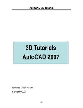
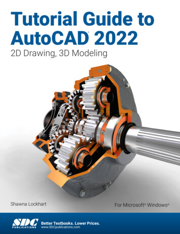
72 Tutorial 2 BASIC CONSTRUCTION TECHNIQUESUsing ArcThe Arc command is on the ribbon Home tab, Draw panel, or you cantype ARC at the command prompt. There are eleven different ways tocreate arcs. To see the options, click on the small triangle next to showthe Arc flyout as shown in Figure 2.20.Each Arc command option requires that you input point locations. Theicons on the buttons help show you which points that option expectsfor input. You can define those point locations by manually typing inthe coordinate values or locating the points with the cursor and click ing your mouse. For the exercises presented in this tutorial, follow thedirections carefully so that your drawing will turn out correctly. Keep inmind that if you were designing the subdivision, you might not use allthe command options demonstrated in this tutorial. When you are usingAutoCAD software later for design, select the command options thatare appropriate for the geometry in your drawing.Arc 3 PointsThe 3 Points option of the Arc command draws an arc through threepoints that you specify. The dots located on the icon represent the threepoints of definition. This means that three point locations will be neces sary for drawing that arc. Remember, to specify locations you can clickthem or type in absolute, relative, or polar coordinates. You will drawan arc using the 3 Points option. The Snap to Node running object snapwill help you click the points drawn in the datafile.Click: 3 Point buttonFigure 2.20Specify start point of arc or [Center]: select point 1, using theAutoSnap marker as shown in Figure 2.21LockediconAs can be seen in Figure 2.21, the AutoSnap marker for Node appearswhen the cursor is near a node point. Notice that when the cursor isright over the point, the locked icon appears to remind you the layer forthe selected item is locked. You cannot make changes to locked layersbut you can still select objects on them.123Figure 2.21Now you will continue with selecting the points.Specify second point of arc or [Center/End]: select point 2The cursor enters drag mode, whereby you can see the arc move onthe screen as you move the cursor. Many AutoCAD commands permitdynamic specification, or dragging, of the image on the screen.
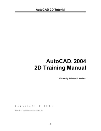
USING ARC 73Move the cursor around the screen to see how it affects the way the arc wouldbe drawn. Recall your use of this feature to draw circles in Tutorial 1.Specify end point of arc: select point 3The third point defines the endpoint of the arc. The radius of the arc iscalculated from the locations of the three points. Your drawing shouldnow show the completed arc, as shown in the upper part of Figure 2.22.New 3 point arc546Figure 2.22Arc Start, Center, EndNext, you will draw an arc by specifying the start, center, and endpoints.Figure 2.22 shows the points used to create this arc.Click: Start, Center, End button from the Arc flyoutSpecify start point of arc or [Center]: select point 4 as the startpointSpecify center point of arc: select point 5 to act as the arc’s centerSpecify end point of arc or [Angle/chord Length]: select point 6 to endthe arcThe arc is drawn counterclockwise from the start point. Notice thatnow Start, Center, End is the top button on the Arc flyout. When youare using a flyout, the last item you clicked appears as the top flyoutbutton, so options you use frequently take only one click.Figure 2.22 shows the point locations needed to draw a concave arc. Ifthe start point were located where the endpoint is, a convex arc outsidethe centerlines would have been drawn. When you have added the arccorrectly, your arc should look like that in the lower part of Figure 2.23.On your own, try drawing another arc with the Arc Start, Center, End option, thistime clicking point 6 first, then the center, and then point 4.Note that this arc is drawn counterclockwise, resulting in a convex arc.Undo this backward arc by typing U [Enter] at the command prompt.Tip: Pressing the space bar or[Enter] key to restart the arccommand uses Arc in
cessible but still visible on the screen. You can’t change anything on a locked layer until you unlock it. Current Layer The current layer is the layer you are working on. Any new objects you draw are added to the current layer. The default current layer is layer 0. If you do not create