Transcription
Limits & Fits
At the end of this presentation, thestudents should be able to : Explain the necessity for tolerancing. Identify the symbols used for fundamental deviation. Identify the numbers used for grades of tolerances. Select fits for mating components. Translate limits and fits symbols to engineering drawings usingBS4500A.
1. Why study Limits & Fits ? Exact size is impossible to achieve. Establish boundaries within which deviation from perfectform is allowed YET still fulfil its design intent. Enable interchangeability of engineering componentsduring assembly.
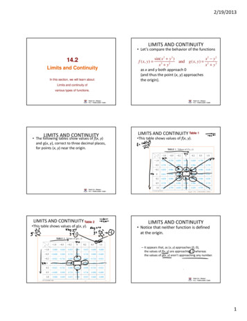
2. Limits (extreme sizes of a part)Tolerance UL – LL 28.2 – 27.8Tolerancezone 0.4Or 0.2Upper limit 28 . 2Zero lineLower limit 27. 8Ø28 0.2(Basic)Shaft
Limits of SizeUnilateral Limits occurs when both maximum limit and minimum limit areeither above or below the basic size.e.g. Ø25 0.18Basic SizeUppers itLowLerimLiitm 0.10Basic Size 25.00 mmUpper Limit 25.18 mmLower Limit 25.10 mmTolerance 0.08 mme.g. Ø25 -0.10Lower LimitUpper LimitsBasic Size-0.20Basic Size 25.00 mmUpper Limit 24.90 mmLower Limit 24.80 mmTolerance 0.10 mm
Limits of SizeFor Unilateral Limits, a case may occur when one of the limits coincideswith the basic size,e.g. Ø25 0.20 , Ø2500-0.10Lower LimitBasic SizeUpper LimitsBilateral Limits occur when the maximum limit is above and theminimum limit is below the basic size.e.g. Ø25 0.04Basic Size 25.00 mmUpper Limit 25.04 mmLower Limit 24.96 mmTolerance 0.08 mm
3. Fits(assembly condition between “Hole” & “Shaft”)Hole –Shaft –A feature engulfing a componentA feature being engulfed by a component
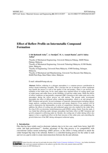
Clearance FitsHoleMax CMin CTolerance zonesnever meetShaftMax. C UL of hole - LL of shaftMin. C LL of hole - UL of shaft
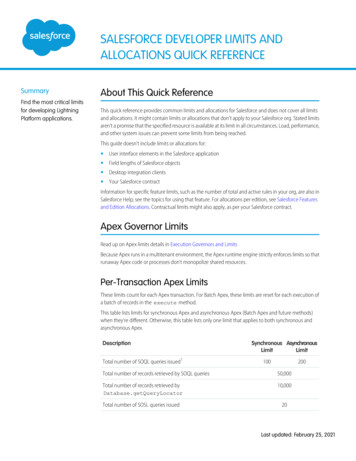
Interference FitsHoleMax IShaftMin ITolerance zonesnever meet butcrosses eachotherMax. I LL of hole - UL of shaftMin. I UL of hole - LL of shaft
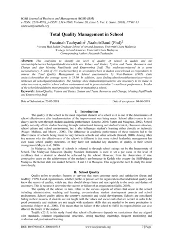
Transition FitsHoleMax CShaftMax ITolerance zonesalways overlapMax. C UL of hole - LL of shaftMax. I LL of hole - UL of shaft
Terminology Related to Limits and FitsMain Menu
µm5520 It is defined graphicallyby the magnitude of theTolerance Zone tolerance and by itsposition in relation to thezero line.Basic Size
4a. Fundamental Deviationis chosen to locate the tolerance zone w.r.t. the zero lineHoles are designated by capital letter:Letters A to G - oversized holesLetters P to ZC - undersized holesShafts are designated by smallletter:Letters m to zc - oversized shaftsLetters a to g - undersized shaftsH is used for holes and h is used for shaftswhose fundamental deviation is zero
Grade is a measure of themagnitude of the tolerance. The lower the grade the finer thetolerance. There are total of 18 gradeswhich are allocated the numbersIT01, IT0, IT1, IT2 . IT16. Fine grades are referred to by thefirst few numbers. As the numbers get larger, so thetolerance zone becomesprogressively wider. Selection of grade should dependson the circumstances. As the grades get finer, the cost ofproduction increases at a sharperrate.Cost4b. Grades of TolerancesGrades of Tolerances
5. Basis of Fits - Hole Basis In this system, the basic diameterof the hole is constant while theshaft size varies according to thetype of fit.Basic SizeITCHole Basis FitsLegends:HoleShaftToleranceC - ClearanceT - Transition I- Interference This system leads to greatereconomy of production, as a singledrill or reamer size can be used toproduce a variety of fits by merelyaltering the shaft limits. The shaft can be accuratelyproduced to size by turning andgrinding. Generally it is usual to recommendhole-base fits, except wheretemperature may have adetrimental effect on large sizes.
Basis of Fits - Shaft BasisBasic Size Here the hole size is varied toproduce the required class of fit with abasic-size shaft.TIShaft Basis FitsLegends:HoleShaftToleranceC - ClearanceT - Transition I- Interference A series of drills and reamers isrequired for this system,therefore it tends to be costly. It may, however, be necessary touse it where different fits arerequired along a long shaft. Forexample, in the case of drivingshafts where a single shaft mayhave to accommodate to a varietyof accessories such as couplings,bearings, collars, etc., it ispreferable to maintain a constantdiameter for the permanentmember, which is the shaft, andvary the bore of the accessories.
Selected ISO Fits- Hole Basis {Table 1.24(a) on Pg 56/57} The ISO system provides many holes and shaft tolerances soas to cater for a wide range of conditions. The following selected hole and shaft tolerances have beenfound to be commonly applied:Selected hole tolerances: H7, H8, H9, H11Selected shaft tolerances: c11, d10, e9, f7, g6, h6, k6, n6, p6, s6 Data sheet 4500A shows a range of fits derived from theseselected hole and shaft tolerances. It covers fits from loose clearance to heavy interference and aresuitable for most general engineering applications. This data sheet covers all basic sizes up to 500 mm.
Selected ISO Fits- Hole Basis (Extracted from BS 4500)Clearance30TransitionInterferenceH11 - c11H7 - k6H7 - p6 130 - 1100 - 240 21 150 2 21 350 22
You must know . Identify fitting conditions fromFundamental deviation. (e.g 30 H7/ g6) Convert from F.D to limits of tolerancefor hole and shaft. (e.g 100 0.5 ) Calculate max. & min. limit of size ofhole and shaft. Max./ Min. Clearance or Interference(for Transition, we have max. clearance and max interference)
6. Application of Tolerances to Dimensions Tolerances should be specified in the case where a dimensionis critical to the proper functioning or interchangeability of acomponent. A tolerance can also be supplied to a dimension which canhave an unusually large variation in size. General tolerances are generally specified as a note at thebottom of the drawing.
Specifications of Tolerances on Drawings(Detailed Parts for Critical Linear Dimensions)(a) Maximum and Minimum LimitsBy specifying directly both limits of size, themaximum limit being quoted first and the samenumber decimal places used in both figures. Thismethod eliminates calculations on the shop floor.(b) Limits of ToleranceBy specifying a size with limits of tolerance in bothdirection stated. In this case, again, the samenumber of decimal places must be used in bothlimits. The larger limit is usually quoted first. If oneof the two deviations in nil, this should beexpressed by the figure 0 (zero).(c) Deviation and GradeBy using the appropriate deviation and gradesymbols H8, g6 and so on, may be quoted with orwithout the limits specified.
Specifications of Tolerances on Drawingson Assembled Parts for Critical Linear Dimensions(a) By specifying the basic size followed by the deviationand grade symbols. The symbols for the hole must beplaced before that of the shaft or above it. If it isnecessary to specify also the numerical value of thedeviations, they should be written in brackets.
Tolerance Accumulation AnalysisThe way a designer dimensions a component and the way eachdimension is toleranced can result in certain amount of tolerancesaccumulated. Two examples of tolerance accumulation check oncomponent dimensions are shown below:
Any QuestionsYou have just learnt:2. Definition of Limits3. Type of fits4. Tolerance zone and size5. Using BS4500 (selection of common fits)6. Tolerances placement on drawing7. Accumulation of tolerances
Limits of Size For Unilateral Limits, a case may occur when one of the limits coincides with the basic size, e.g. Ø25 0.20,Ø25 0 0-0.10 Basic Size Lower Limit U pper L imits Bilateral Limits occur when the maximum limit is above and the minimum limit is below the basic size. e.g. Ø25 0.04 Basic Size 25.00 mm Upper Limit 25.04 mm Lower .