Transcription
sccemechanical.wordpress.comA.NARENDRA Asst. ProfDEPARTMENT OF MECHANICAL ENGINEERING, SCCE Karimnagarsccemechanical.wordpress.comPRODUCTION DRAWING ANDPRACTICE
Dept. of Mechanical EngineeringUNIT ISCCE, KarimnagarSheet no.1Representation Materials & Machine Componentssccemechanical.wordpress.com
Dept. of Mechanical EngineeringSCCE, al.wordpress.com
Dept. of Mechanical EngineeringSCCE, Karimnagarsccemechanical.wordpress.com
Dept. of Mechanical EngineeringSCCE, al.wordpress.com
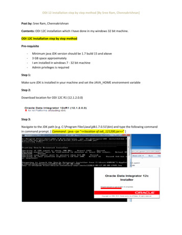
Dept. of Mechanical EngineeringUNIT –IILIMITS and FITSSCCE, KarimnagarSheet No.2LIMIT SYSTEMFollowing are some of the terms used in the limit system,Tolerance: The permissible variation of a size is called tolerance. It is the difference between the maximum and minimumpermissible limits of the given size.Limits: The two extreme permissible sizes between which the actual size is contained are called limits. The maximum sizeis called the upper limit and the minimum size is called the lower limit.Deviation: It is the algebraic difference between a size (actual, maximum, etc.) and the corresponding basic size.Actual Deviation: It is the algebraic difference between the actual size and the corresponding basic size.Upper Deviation: It is the algebraic difference between the maximum limit of the size and the corresponding basic size.Lower Deviation: It is the algebraic difference between the minimum limit of the size and the corresponding basic size.Allowance: It is the dimensional difference between the maximum material limits of the mating parts, intentionallyprovided to obtain the desired class of fit. If the allowance is positive, it will result in minimum clearance between the mating partsand if the allowance is negative, it will result in maximum interference.sccemechanical.wordpress.comFITSThe relation between two mating parts is known as a fit. Depending upon the actual limits of the hole or shaft sizes, fits maybe classified as clearance fit, transition fit and interference fit.Clearance Fit: It is a fit that gives a clearance between the two mating parts.Transition Fit: This fit may result in either an interference or a clearance, depending upon the actual values of the toleranceof individual parts.Interference Fit: If the difference between the hole and shaft sizes is negative before assembly; an interference fit isobtained.HOLE BASIS SYSTEM, SHAFT BASIS SYSTEMIn working out limit dimensions for the three classes of fits; two systems are in use, viz., the hole basis system and shaft basis systemHOLE BASIS SYSTEM: In this system, the size of the shaft is obtained by subtracting the allowance from the basic size of the hole. Inthis system, the lower deviation of the hole is zero. The letter symbol for this situation is ‘H’.SHAFT BASIS SYSTEM: In this system, the size of the hole is obtained by adding the allowance to the basic size of the Shaft. Tolerancesare then applied to each part. In this system, the upper deviation of the shaft is zero. The letter symbol for this situation is ‘h’.
Dept. of Mechanical EngineeringSCCE, al.wordpress.com
Dept. of Mechanical EngineeringSCCE, Karimnagarsccemechanical.wordpress.com
Dept. of Mechanical EngineeringSCCE, KarimnagarDatum feature: A datum feature is a feature of a part, such as an edge, surface, or a hole, which forms the basisfor a datum or is used to establish its locationUNIT et no.3FORM AND POSITIONAL TOLERANCESsccemechanical.wordpress.com
Dept. of Mechanical EngineeringSCCE, Karimnagarsccemechanical.wordpress.com
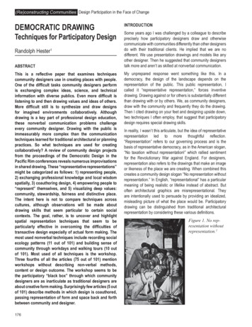
Dept. of Mechanical EngineeringSCCE, ΘΘUNIT IV &UNIT VSheet no.4Surface Roughness and its Indication &Heat and Surface Treatment SymbolsSurface Roughness: The properties and performance of machine components are affected by the degree of roughness of the various surfaces.The higher the smoothness of the surface, the better is the fatigue strength and corrosion resistance. Friction between mating parts is also reduceddue to better surface finish.Surface Roughness Number: The surface roughness number represents the average departure of the surface from perfection over a prescribedsampling length and is expressed in microns.The surface roughness may be measured, using any one of the following:1. Straight edge 2. Surface gauge3. Optical flat4. Tool maker’s microscope5. Profilometer6. Profilograph 7. Talysurf.sccemechanical.wordpress.comMachine Symbols: The basic symbol consists of two legs of unequal length, inclined at approximately 60 to the line, representing the surfaceconsidered. This symbol may be used where it is necessary to indicate that the surface is machined, without indicating the grade of roughness orthe process to be used.a. Basic symbol.b. Material Removal isNot Allowedc. Removal OfMaterial Is Allowed.d. Special surfacecharacteristics
Dept. of Mechanical EngineeringSCCE, Karimnagara.b.c.d.e.Roughness Number,Type Of machining Process,C(f): Sampling Length,Direction Of Lay,Machining Allowancesccemechanical.wordpress.comIndication of Special Roughness Characteristics: In certain circumstances, for functional reasons, it may be necessary tospecify additional special requirements, concerning surface roughness. If it is required that the final surface texture beproduced by one particular production method, this method should be indicated on an extension of the longer arm of thesymbol. Also, any indications relating to treatment of coating may be given on the extension of the longer arm of thesymbol.
Dept. of Mechanical EngineeringSCCE, al.wordpress.com
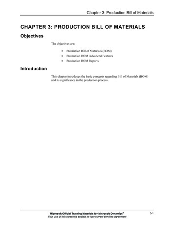
Dept. of Mechanical EngineeringSCCE, KarimnagarUNIT VISheet No: 5-17DETAILED and PART DRAWINGSStuffing Box is used to prevent loss of fluid such as steam, between sliding or turning parts ofmachine elements. In a steam engine, when the piston rod reciprocates through the cylinder cover;stuffing box provided in the cylinder cover, prevents leakage of steam from the cylinder.sccemechanical.wordpress.com
Dept. of Mechanical EngineeringSCCE, Karimnagarsccemechanical.wordpress.comCrosshead is used in horizontal steam engines for connecting the piston rod and connecting rod.The crosshead, with the help of slide block 4, reciprocates between two guides provided in the engineframe. The gudgeon pin 3, connects the slide blocks with the crosshead block 1. This acts as a pin jointfor the connecting rod (not shown in figure). The piston rod 2 is secured to the crosshead block by meansof the cotter 5. The assembly ensures reciprocating motion along a straight line for the piston rod andreciprocating cum oscillatory motion for the connecting rod.sccemechanical.wordpress.com
Dept. of Mechanical EngineeringSCCE, KarimnagarEccentric is used to provide a short reciprocating motion, actuated by the rotation of a shaft.Eccentrics are used for operating steam valves, small pump plungers, shaking screens, etc. Rotarymotion can be converted into a reciprocating motion with an eccentric, but the reverse conversion isnot possible due to excessive friction between the sheave and the strap. The sheave 2 which is in theform of a circular disc with a stepped rim is keyed on the shaft. When the shaft rotates, the sheaverotates eccentrically because of the eccentrically placed hole in it and imparts reciprocating motion toeccentric rod 6. The straps 1 are semi-circular elements with an annular recess to accommodate thestepped rim of the sheave. These are held together on the sheave by means of strap bolts 4, with packingstrips 3 placed between them. The eccentric rod is fixed to the eccentric strap by means of the studsand nuts 5.sccemechanical.wordpress.com
Dept. of Mechanical EngineeringSCCE, Karimnagarsccemechanical.wordpress.comConnecting rod is used in center crank engines. The bearing bush 4 which is in one piece, is fittedat the small end of the connecting rod 1. The small end of the rod is connected to the piston. The mainbearing bush, which is split into two halves, is placed at the big end of the connecting rod. The big endof the rod is connected to the crank pin of the center crank. First, the split bearing brasses 3 are placedon the crank pin, then the big end of the connecting rod and the cap 2 are clamped onto these, by meansof two bolts 5 and nuts 6.sccemechanical.wordpress.com
Dept. of Mechanical EngineeringSCCE, KarimnagarScrew jacks are used for raising heavy loads through very small heights. In this, the screw 3 worksin the nut 2 which is press fitted into the main body 1. The tommy bar 7 is inserted into a hole throughthe enlarged head of the screw and when this is turned, the screw will move up or down, thereby raisingor lowering the load.sccemechanical.wordpress.com
Dept. of Mechanical EngineeringSCCE, Karimnagarsccemechanical.wordpress.comPipe vices are designed for holding pipes, to facilitate operations such as threading or cutting-offto required length. To assemble the vice, the screw rod 4 is screwed into the base 1 from above. Whenthe circular groove at the end of the screw rod is in-line with the 6 mm diameter transverse hole in thehousing, the movable jaw 2 is inserted from below. After alignment, two set screws 3 are inserted intothe jaw. This arrangement allows the jaw to move vertically without rotation when the handle isoperated and the screw is turning. The V-shaped base of the housing can accommodate pipes ofdifferent diameters. The serrations provided on the V-shaped end of the movable jaw provide effectivegrip on the pipe surface.sccemechanical.wordpress.com
Dept. of Mechanical EngineeringSCCE, KarimnagarPlummer block is used for long shafts, requiring intermediate support, especially when the shaftcannot be introduced into the bearing, end-wise. The bottom half 2 of the bearing brass is placed in thebase 1 such that, the snug of the bearing enters into the corresponding recess in the base; preventingrotation of the brasses. After placing the journal (shaft) on the bottom half of the bearing brass, kept inthe base; the upper half of the bearing brass 3 is placed and the cap 4 is then fixed to the base, by meansof two bolts with nuts 5. The bearing is made of two halves so that the support can be introduced at anylocation of the long shaft.sccemechanical.wordpress.com
Dept. of Mechanical EngineeringSCCE, Karimnagarsccemechanical.wordpress.comLathe tool post supports one cutting tool at a time and is used on small sized lathes. This unit isfixed on the compound rest of the lathe carriage. The tool post consists of a circular body 1 with a collarat one end and a threaded hole at the other. A vertical slot is provided in the body to accommodate thetool/tool holder. The body is slid through the square block 5, which is finally located in the T-slot,provided in the compound rest. The design permits rotation of the body about the vertical axis. A circularring 4 having spherical top surface is slid over the body and the wedge 3 is located in the vertical slot.The tool / tool holder is placed over the wedge. By sliding the wedge on the ring, the tool tip level canbe adjusted. The tool is clamped in position by means of the square headed clamping screw 2, passingthrough the head of the body.sccemechanical.wordpress.com
Dept. of Mechanical EngineeringSCCE, KarimnagarOldham coupling is known as a non-aligned coupling and is used to connect two parallel shafts,whose axes are at a small distance apart. The two flanges 1 are mounted on the ends of shafts 3 bymeans of sunk keys 4. The flanges are having rectangular slots in them. These flanges are set such that,the slots in them are at right angle to each other. The circular disc 2 is now positioned in-between themso that the projections in the circular disc, enter into the corresponding slots of the flanges. Duringrotation of the shafts, the central disc slides in the slots of the flanges.sccemechanical.wordpress.com
Dept. of Mechanical EngineeringSCCE, Karimnagarsccemechanical.wordpress.comUniversal coupling is a rigid coupling and is used to connect two shafts, whose axes intersect ifextended. The forks 2 are mounted at the ends of two shafts 1, making use of sunk keys 6. The centralblock 3, having two arms at right angle to each other, is placed between the forks and connected toboth of them by using pins 4 and collars 5. A taper pin (not shown) is used to keep the pins 4 in position.During rotation of shafts, the angle between them can be varied.sccemechanical.wordpress.com
Dept. of Mechanical EngineeringSCCE, KarimnagarSafety or relief valves are used as boiler mountings and they let off steam from inside the boilerWhenever the pressure exceeds the set value. Thus, these valves safe guard the boilers. The pressuremay be set by using a dead weight or a tension spring with tension adjustment arrangement. Springloaded relief valve in which a tension spring is used to set a pre-determined value for the steam pressurein the boiler. Valve 3 is placed vertically inside the valve body 1 and the valve seat is an integral part ofthe valve body, in the design considered. Stem 6 is located in the valve, with pointed end entering intothe valve. Flange 7 is now placed over this assembly and fastened to the valve body by fulcrum bolt 4.Lever 2 is attached to the fulcrum bolt by using the fulcrum pin 5 such that, the lever rests on the stem6. One end of the tension spring 8 is attached to the lever and the other end to the tension adjustingbolt 9. The tension adjusting bolt is attached to a base and the spring tension can thus be adjusted toany required value.sccemechanical.wordpress.com
Dept. of Mechanical EngineeringSCCE, Karimnagarsccemechanical.wordpress.comAir cock valve is used to control air or gas supply. It consists of a plug 2 which is inserted into thebody 1, from the bottom. The rectangular sectioned spring 4 is placed in position at the bottom of theplug and seated over the screw cap 3. The screw cap is operated to adjust the spring tension. Lever 5with square hole is used to operate the cock. By a mere 90 turn, the cock is either opened or closedfully.sccemechanical.wordpress.com
ΘΘΘΦΦΘΘΘ UNIT IV & Sheet no.4 UNIT V Surface Roughness and its Indication & Heat and Surface Treatment Symbols Surface Roughness: The properties and performance of machine components are affected by the degree of roughness of the various surfaces. The higher the smoothness of the surface, the