Transcription
NXP Motor Control ToolboxFor MATLAB/Simulink Modeling and Code GenerationMike Cao , NXP Automotive Senior FAE
Introduction: Model Based Design (MBD) Model Based Design is becoming more common during the normal course of software development to explain and implementthe desired behavior of a system. The challenge is to take advantage of this approach and get an executable that can besimulated and implemented directly from the model to help you get the product to market in less time and with higher quality.This is especially true for electric motor controls development in this age of hybrid/electric vehicles and the industrial motorcontrol application space. Many companies model their controller algorithm and the target motor or plant so they can use a simulation environment toaccelerate their algorithm development. The final stage of this type of development is the integration of the control algorithm software with target MCU hardware. Thisis often done using hand code or a mix of hand code and model-generated code. NXP’s Model Based Design Toolbox allowsthis stage of the development to generate 100% of the code from the model.
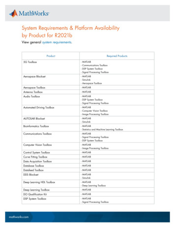
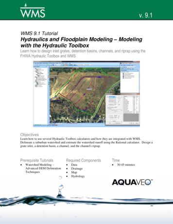
Introduction: Reduce Development Time With MBD ToolboxSystemRequirementsModeling/SimulationWith MC library andMBD Toolbox, testModel using targetMCU and compilerthrough PIL testing.Use software-based model vs.paper-based method, and starttesting at very earliest stage.Fewer defects found in thisphase of testing, wherefinding defects is expensive.Functional TestingConvert model to SILand now can test ANSIgenerated software. Canalso use MDB librarywith SIL testing.HIL TestingRapid PrototypeWith MC Toolbox, auto-generatecode for direct interface ofperipherals for target hardwarewithout any manual hand code.Now that more testing ontarget has occurred earlierin the process, HIL testingtime is reduced.Target MCUImplementationTimeUsing NXP’s Model Based Design Toolbox you can reduce development time from this.Reduce Timefrom This. . .
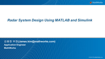
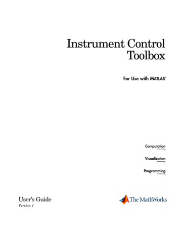
Introduction: Reduce Development Time With MBD ToolboxSystemRequirementsFunctional TestingModeling/SimulationHIL TestingRapid PrototypeTo This!Target MCUImplementationTime
Introduction: What Do We Do? One of the Automotive ToolsEnablement & Engineeringgroup’s objectives is to developsoftware enablement tools toassist our customers with rapidprototyping and acceleratealgorithm development on theirtarget NXP MCU This includes software tools thatautomatically generateperipheral initialization codethrough GUI configuration, togenerating peripheral drivercode from a Model Based Designenvironment like Simulink Exposure to NXP’s hardware/software enablementNXP DEVKIT-MPC5744PNXP S32K EVB KitModel Based DesingToolboxwith Simulink Model-based designDriver configurationAssignment to pinsInitialization setupMTRCKTSBNZVM128RAppID Bootloader UtilitySignal Visualizationand Data Acquisition Tool
Model Based Design Toolbox Overview The Model Based Design Toolbox includes an embedded target supporting NXP MCUs and Simulink plug-in libraries which provide engineers with anintegrated environment and tool chain for configuring and generating the necessary software, including initialization routines, device drivers, and areal-time scheduler to execute algorithms specifically for controlling motors. The toolbox also includes an extensive Automotive Math and Motor Control Function Library developed by NXP’s renowned Motor Control Center ofExcellence. The library provides dozens of blocks optimized for fast execution on NXP MCUs with bit-accurate results compared to Simulink simulationusing single-precision math. The toolbox provides built-in support for Software and Processor-in-the-Loop (SIL and PIL), which enables direct comparison and plotting of numericalresults.MathWorks products required for MBD Toolbox:MATLAB (32-Bit or 64-Bit)SimulinkMATLAB CoderSimulink CoderEmbedded Coder
MBD Toolbox: Toolbox Library ContentsSimulinkLibrariesMBDToolboxLibrary for S32KMBDToolboxPeripheral blocklibrary
MBD Toolbox: Toolbox Library ContentsPeripherals General–––– Compiler OptionsADC conversionDigital I/OPIT timerISR Communication Interface ––– Configuration/Modes CAN driverSPI driverI2C Motor Control Interface––––––––––Cross triggering unitPWMeTimer block(s)Sine wave generationADC Command ListGDU (Gate Drive Unit)PTU (Prog Trigger Unit)TIM Hall Sensor PortFTM (Flex Timer Module)PDB (Programmable DelayBlock) CodeWarriorWind River DIABGreen HillsCosmicIARGCCRAM/FLASH targetsSimulation ModesNormal Accelerator Software in the Loop (SIL) Processor in the Loop (PIL) MCU OptionMultiple packages Multiple Crystal frequencies UtilityFreeMASTER Interface Data acquisition /Calibration Customize GUI Profiler Function Exec. time measurement Available in PIL Available in standalone Memory Read and Write MCUs Supported MPC5643LMPC567xKMPC574xPS12ZVMS32K
MBD Toolbox: Auto Math and Motor Control Library ContentsGeneral MotorControl LibraryGeneral DigitalFilters LibraryGeneralFunctionLibraryMathematicalLibrary
MBD Toolbox: Auto Math and Motor Control Library ContentsMLIB Absolute Value, Negative ValueMLIB Abs, MLIB AbsSat MLIB Neg, MLIB NegSatAdd/Subtract Functions MLIB Add, MLIB AddSat MLIB Sub, MLIB SubSatMultiply/Divide/Add-multiplyFunctions MLIB Mul, MLIB MulSat MLIB Div, MLIB DivSat MLIB Mac, MLIB MacSat MLIB VMacShifting MLIB ShL, MLIB ShLSat MLIB ShR MLIB ShBi, MLIB ShBiSatNormalisation, Round Functions MLIB Norm, MLIB RoundConversion Functions MLIB ConvertPU, MLIB ConvertGFLIB Trigonometric FunctionsGFLIB Sin, GFLIB Cos,GFLIB Tan GFLIB Asin, GFLIB Acos,GFLIB Atan, GFLIB AtanYX GFLIB AtanYXShiftedLimitation Functions GFLIB Limit, GFLIB VectorLimit GFLIB LowerLimit,GFLIB UpperLimitPI Controller Functions GFLIB ControllerPIr,GFLIB ControllerPIrAW GFLIB ControllerPIp,GFLIB ControllerPIpAWInterpolation GFLIB Lut1D, GFLIB Lut2DHysteresis Function GFLIB HystSignal Integration Function GFLIB IntegratorTRSign Function GFLIB SignSignal Ramp Function GFLIB RampSquare Root Function GFLIB Sqrt GDFLIB Finite Impulse FilterGDFLIB FilterFIR Moving Average Filter GDFLIB FilterMA 1st Order Infinite ImpulseFilter GDFLIB FilterIIR1init GDFLIB FilterIIR1 2nd Order Infinite ImpulseFilter GDFLIB FilterIIR2init GDFLIB FilterIIR2GMCLIB Clark TransformationGMCLIB ClarkGMCLIB ClarkInvPark Transformation GMCLIB Park GMCLIB ParkInvDuty Cycle Calculation GMCLIB SvmStdElimination of DC Ripples GMCLIB ElimDcBusRipDecoupling of PMSM Motors GMCLIB DecouplingPMSM
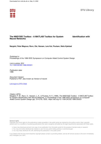
MBD Toolbox: RAppID Bootloader UtilityThe RAppID Bootloader works with the built-in Boot Assist Module (BAM) included in the NXP Qorivva and also supports S12MagniV, Kinetis, and DSCs family of parts. The Bootloader provides a streamlined method for programming code into FLASH orRAM on either target EVBs or custom boards. Once programming is complete, the application code automatically starts.Modes of OperationThe Bootloader has two modes of operation: for use as a stand-alone PC desktop GUI utility, or for integration withdifferent user required tools chains through a command line interface (i.e. Eclipse Plug-in, MATLAB/Simulink, )MCUs SupportedMPC5534, MPC5601/2D, MPC5602/3/4BC, MPC5605/6/7B, MPC564xB/C, MPC567xF, MPC567xK, MPC564xL,MPC5604/3P, MPC574xP, S12ZVM, S32K, KV10, KV3x, KV4x, KV5x, 56F82xx and 56F84xx.Graphical User InterfaceCommandLineStatus given in two stages:Bootloader download, thenapplication programming
FreeMASTER — Run Time Debugging ToolUser-friendly tool for real-time debug monitor and datavisualization Completely non-intrusive monitoring ofvariables on a running system Display multiple variables changing over timeon an oscilloscope-like display, or view the datain text form Communicates with an on-target driver via USB,BDM, CAN, UARTEstablish a Data Trace on Target Set up buffer (up to 64 KB), sampling rate andtrigger Near 10-µs RTJTAGEthernet
MBD Toolbox: Summary of Application SupportSYSTEM APPLICATIONUser ApplicationSoftwareApplication ripheralsDigital filteringGeneral functionsMC library setDriversEfficientReflecting the chip featuresSystem rget PlatformGMCLIBMotor ControlDocumentationAPIPINSExternal HardwareExternalConnections
Model Based Design Steps: Step 1 (Simulation)Simulation in PC environmentPWM AADCTorqueControlIQloop IQcmdVacmdReverseParkTransformIDloop mdIDcmdPWM tor PositionController ModelElectric Motor ModelPC EnvironmentGateDriverIDIQAnalogSensor ModelPWM BIBICAnalogDevice ModelIdealized simulation of the controller and themotor to refine the control technique. Doneon host PC without regard for embeddedcontroller. Can optionally add analog devicemodels for fault detection and signal control.
Model Based Design Steps: Step 2 (SIL)(SIL) Generated code executes as atomic unit on PCPWM AADCTorqueControlIQloop IQcmdVacmdReverseParkTransformIDloop mdIDcmdPWM BPWM IQMotor PositionAnalogSensor ModelController ModelElectric Motor ModelPC EnvironmentGateDriverIBICAnalogDevice ModelStill done on host PC without regard forembedded controller. Instead using generated Ccode that is compiled using a PC-based compiler.Run same test vectors as in simulation for C CodeCoverage analysis and verify functionality.
Model Based Design Steps: Step 3 (PIL)(PIL) Executes generated code on the target MCUPWM AADCTorqueControlIQloop IQcmdVacmdReverseParkTransformIDloop mdIDcmdPWM tor PositionController ModelElectric Motor ModelPC Environment MCUGateDriverIDIQAnalogSensor ModelPWM BIBICAnalogDevice ModelExecute the model on the target MCU and performnumeric equivalence testing. Co-execution with MCU andModel Based Design working together while collectingexecution metrics on the embedded controller of thecontrol algorithm. Validate performance on the MCU.
Model Based Design Steps: Step 3 (PIL)Verification and Validation at Code Level This step allows: Translation validation through systematic testing To demonstrate that the execution semantics of the model are being preserved during code generation, compilation, andlinking with the target MCU and compiler Numerical Equivalence Testing: Equivalence Test Vector Generation Equivalence Test Execution Signal Comparison
Example IEC 61508 and ISO 26262 Workflow for Model-Based Design with MathWorks Products*Model advisor, modelingstandards checkingSimulation (model testing),model coverage, RMISimulink / Stateflow / Simulink Fixed Point*Workflow from The MathworksTMPresentation Material Model-BasedDesign for IEC 61508 and ISO 26262PIL testing using MC Toolbox PIL Mode Support**Real-Time Workshop Embedded Codertraceability report or model vs. codecoverage comparisonReal-Time Workshop Embedded Coder** NXP MC Toolbox is part of Mathworks Workflow outlined in TheMathworksTM Material Model-Based Design for IEC 61508 and ISO26262 as well as part of certification qualification tool suite.
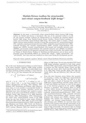
Model Based Design Steps: Step 4 (Target MCU)*PWM AADCTorqueControlIQloop PIFilterIQcmd-ReverseParkTransformIDloop ZeroVacmdPIFilterPWMModulationVbcmdIDcmdPWM BPWM VbForwardClarkTransformIQIBICMotor PositionOutputDrivers*Controller ModelInputDrivers** I/O peripheral driver blocks canbe included in the model, providingthe analog driver interfaces neededto directly interface to devicesexternal from the MCU.Execute on Target MCU on ECM/EVBMCU withEmbedded ControlModule (ECM)Electric MotorGenerate production code to run on embedded MCU with real motorwhile collecting execution metrics on the embedded controller of controlalgorithm. Validate performance on MCU and use FreeMASTER to tunecontrol parameters and perform data logging.
Model Based Design Steps: SummaryPWM ATorqueControl IQloopPIFilterIQcmdIDloopPIFilterIDcmd- ZeroVacmdReverseParkTransformPWM ATorqueControlPWMModulationVbcmd IQloopPIFilterIQcmdIDloopPIFilterIDcmd-PWM B PWM mdIDloopPIFilterIDcmd- mIQ rdParkTransformIBTorqueControlPWM BPWM CIAIDForwardClarkTransformPWM APWMModulationVbcmd-VaIDVb PWM BPWM CZeroVaForwardParkTransformPWM ATorqueControlPWMModulationVbcmd-GateDriverIB ZeroVacmdReverseParkTransformPWMModulationVbcmdPWM BPWM rmIQMotor PositionMotor PositionIBGateDriverICMotor PositionMotor PositionController ModelController ModelElectric Motor ModelElectric Motor ModelPC EnvironmentStep 1 — System Requirements:MBD Simulation OnlySoftware requirementsControl system requirementsOverall application control strategyModeling style guidelines appliedAlgorithm functional partitioningInterfaces are defined herePC EnvironmentStep 2 — Modeling/Simulation:MBD Simulation with ANSI C Code using SILControl algorithm designCode generation preparationControl system designOverall application control strategy designStart testing implementation approachTesting of functional components of algorithmTest harness to validate all requirementsTest coverage of model hereCreates functional baseline of modelController ModelController ModelElectric Motor ModelPC Environment MCUStep 3 — Rapid Prototype:MBD Simulation with ANSI C Code using PILController code generationDetermine execution time on MCUVerify algorithm on MCUSee memory/stack usage on MCUStart testing implementation approachTarget testing controls algorithm on MCURefine model for code generationFunction/File partitioningData typing to target environment done hereScaling for fixed point simulation and code genTesting of functional components of algorithmTest harness to validate all requirementsTest coverage of model hereCreates functional baseline of modelEquivalence testingElectric MotorMCU withEmbedded ControlModule (ECM)Step 4 — Target MCU ImplementationANSI C Code Running on Target Hardware andMCUValidation/verification phaseController code generationDetermine execution time on MCUStart testing implementation on target ECMCode generate control algorithm I/O drivers. Complete implementation on ECM.Test system in target environment Utilizecalibration tools for data logging and parametertuningExecute code on target MCUFunctional testing in target environmentEnsure execution on target is correct as well ascode generation on target is performing asdesired.
How to get it and where to find support Download MBD Toolbox: www.nxp.com/mctoolbox MATLAB: www.mathworks.com Support: https://community.nxp.com/community/mbdt
Thank you
The final stage of this type of development is the integration of the control algorithm software with target MCU hardware. This is often done using hand code or a mix of hand code and model-generated code. NXP's Model Based Design Toolbox allows this stage of the development to generate 100% of the code from the model.