Transcription
POWER SYSTEMS topics 103Sizing gensets for motor startingA practical guide to understanding how motor-starting loads affect genset performanceBy:Dan KruegerSenior FieldApplications EngineerKohler PowerSystems-AmericasRick Van MaarenSenior Staff EngineerKohler PowerSystems-AmericasToday’s standby power loads aremore complex than ever before. Inmany industrial and commercialapplications, standby gensets mustsupply power to a mixture of linearand nonlinear loads in addition tolarge motor loads that cycle on andoff. Of all the diverse loads a standbygenset must supply, applications withmotors present the most sizing issues.The dynamic interactions of motorsand gensets – along with the impactof motor starters, system inertia,motor loading, frequency dip, gensetpreload and nonlinear loading – makemanual genset sizing difficult, ifnot impossible.Not only is sizing an applicationwith large motors complex, butdifferent genset manufacturers havedifferent approaches for specifyinga standby power system thatwill function reliably. Each majorgenset manufacturer has createdgenset-sizing software to helpwith this complex task, but due tomanufacturers’ differing approachesto motor starting, this softwarecan yield quite different results –sometimes specifying a larger andmore expensive generator or too smalla generator than is necessary forKohlerPower.comreliable operation. The purposeof this article is to explain howmotors affect genset performanceand how sizing software, such asKohler Power System’s QuickSize ,deals with motor loads. Armedwith this understanding, powersystem specifiers will be able toselect the most cost-effective andreliable genset for motorstarting applications.Basic characteristics ofmotor loadsMotor loads cause difficulty because amotor draws high current when startedat full voltage. Starting current is typicallysix times a motor’s rated full-load current,and this inrush current stays high until themotor reaches about 75 percent of ratedspeed. When a motor is started on normalutility power, the high inrush current willcause only a small voltage dip becausethe utility is a more robust voltage source.However, when a motor is started ongenset power, the high inrush currents(measured in kilovolt-amperes or KVAs) canresult in a large voltage dip that can inhibitthe motor from reaching itsoperating speed.The challenge, then, is to size the gensetto handle the motor-starting load, but also 2009by Kohler Co.
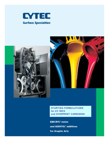
POWER SYSTEMS topics 103Letter DesignationKVA per Horsepowerwith Locked RotorA0 - 3.14B3.15 - 3.54C3.55 - 3.99D4.0 - 4.49E4.5 - 4.99F5.0 - 5.59G5.6 - 6.29H6.3 - 7.00J7.1 - 7.99K8.0 - 8.99L9.0 - 9.99M10.0 - 11.10N11.2 - 12.49P12.5 - 13.99R14.0 - 15.99S16.0 - 17.99T18.0 - 19.99U20.0 - 22.39V22.4 and upManufacturers Association (NEMA) sets designstandards for motors and has established aNEMA code-letter designation for classifyingmotors according to the ratio of locked-rotorKVAs (LRKVAs) per horsepower. These codeletters range from A to V, covering motors withan LRKVA-per-horsepower ratio of 3.14 or lessto a ratio of 22.4 LRKVA-per-horsepower ormore. See Figure 1.For example, a 50 hp Code F motor requires279.5 LRKVA per horsepower upon starting(50 hp x 5.59 LRKVA per hp 279.5 LRKVA/hp).LRKVA is also known as “starting KVA”or “SKVA.”Small motors have a higher NEMA codeletter and correspondingly higher LRKVA-perhorsepower requirement than large motors.Typical motor sizes and codes are shown inFigure 2.Figure 1: Locked Rotor Indicating Code LettersSource: 2006 NEMAVoltage dipto minimize the impact on the other connectedloads that may be affected by voltage dips orfrequency dips.Therefore, when sizing a genset, it is criticalto accurately predict voltage dips and tounderstand how much excess starting capabilityis available in the motor and what amount ofvoltage dip can be allowed. The most commonmethodology for sizing gensets for motorstarting focuses on understanding allowableinstantaneous voltage dips, as theprimary criteria. However, there isSizeone manufacturer that considersallowable sustained voltage dips1 - 2 HPas the primary criteria for3 HP5 HPmotor-load starting.The motor-starting KVA canbe determined by the motor’snameplate. The National ElectricalKohlerPower.comp. 2The KVA requirements of a motor running atfull load and rated speed are normally less thanone KVA per horsepower. With the possibleexception of small motors, it would be overlyconservative to size a genset set simply bymatching the alternator’s KVA to the motor’sKVA. This would typically result in a gensetwith more than twice the capacity necessary.However, due to the dynamic interaction of thesystem components, several characteristicscombine to make this approach impractical.CodeLocked RotorKVA/HPL or M9 - 11K8- 9J7-87.5 - 10 HPH6-715 HP and upG5.6 - 6.3Figure 2: Typical Code Letters for Various HP MotorsSource: 2006 NEMA
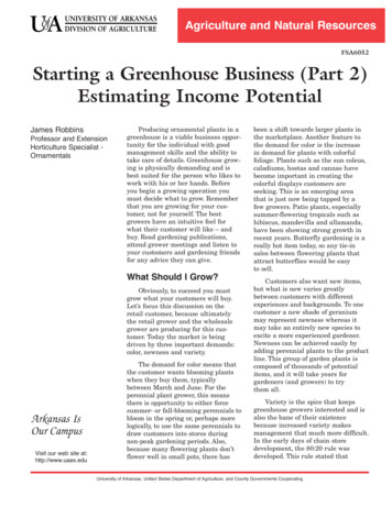
POWER SYSTEMS topics 103HPEINGNEAKV/PHAT80.PFF.4 PT0AA/KVHPEGINENValues for motor LRKVA are based on fullvoltage starting. In practice, there is alwaysa voltage dip when a motor is started ongenset power, and there is even a small dipwhen a motor is started on utility power.When the voltage drops, inrush current is alsoproportionally reduced so that starting KVA isreduced as the square of the voltage dip. A 30percent voltage dip reduces starting KVA byabout 50 percent (0.7 kilovolts x 0.7amps 0.49 KVA).At least for the first few cycles, the voltageAMPS OR KVA0.4 Power Factor 50% HP FactorFigure Power3. EnginePowerFigure 3: EngineRequiredforRequiredfor LowPower Factor LoadLow Power-FactorLoadSource: Kohler Power SystemsThe first characteristic is power factor. Threephase genset sets are usually rated in KVA at 0.8power factor. Starting power factors of motorsvary from 0.3 to 0.5 and increase towards unityas the motor accelerates and its KVA demanddrops. With a 0.4 power-factor load, a typicalgenset is capable of producing nearly twiceits continuous-rated KVA for the time requiredto accelerate a motor to the speed at whichits KVA requirement drops sharply. The gensetengine will not stall even though it is being askedto supply more than its rated KVA, becauselow power-factor loads (see Figure 3) do notrequire as much horsepower as higher powerfactor loads. This genset characteristic allowssatisfactory motor-starting results with a gensethalf the size predicted by the conservativeapproach, which matches the genset 0.8 powerfactor KVA rating to the motor-LRKVA rating.Voltage dipThe other characteristic that can substantiallyreduce the size of the genset needed for aparticular motor-starting load is voltage dip.KohlerPower.comp. 3dip is determined by the size of the load(i.e., the motor’s LRKVA) and the reactance ofthe alternator – which is somewhat proportionalto the total mass of copper and iron present inthe alternator. The issue in sizing a genset isdetermining what voltage dip will be acceptablefor a particular load when considering its effecton all components in the system, some ofwhich may have unknown transientacceptance specifications.A voltage dip can affect motors themselves,in addition to other loads on the system. Forexample, excessive voltage dip can causecontrol relays or magnetically held motorstarting contactors to drop out, or ultimately,cause the motor to not start at all. If the relaysor contactors drop out, the load is removedfrom the genset, causing voltage to rise andthe cycle to repeat rapidly. This can damagecontactors if allowed to continue. Most controlrelays and motor-starting contactors will toleratea 35 percent voltage dip. However, there areexceptions. Some relays or contactors willstart to chatter if subjected to a voltage dip aslittle as 20 percent. Likewise, other voltagesensitive loads need to be accounted for(e.g., UPS systems, medical equipment, HIDlighting) in any genset-sizing exercise. To ensuresatisfactory operation on a given standby power
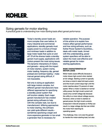
POWER SYSTEMS topics 103Motor starters can reducevoltage dipsystem, consult the voltage/frequencylimitations of control components from themanufacturers or suppliers.The high inrush current and high startingtorque associated with full-voltage startingof motors on utility power may createproblems with the equipment driven bythe motor, or the voltage dips may raiseobjections from the electric utility. Tocircumvent these issues, many facilitiesuse various types of motor starters for theirmotors. Some of these devices also benefitmotor starting when running on gensetpower, often allowing a smaller genset tobe utilized.Voltage dips also reduce the torque amotor can supply to its load. A commonNEMA Design B motor will develop 150percent of rated full-load torque duringstarting. Torque is proportional to the KVAdelivered to the motor, so a 30 percentvoltage dip that reduces KVA to 49 percentalso reduces torque to 49 percent of itsrating. If the motor starts unloaded – asmost fans, centrifugal pumps and motorsused with elevators do – this torquereduction produces no problem other thana somewhat longer acceleration time.Other types of loads, such as positivedisplacement pumps, may require moreClosed TransitionOpen Transition664Line Circuit4Line CircuitReduced-voltage starters – Mostreduced-voltage starters connect the loadto the power source in two or more steps.The starters may be either “open”- or“closed”-transition starters, but only closedtransition, reduced-voltage starters arehelpful when running on genset power. Asseen in Figure 4, open-transition starterscreate an unacceptable spike in KVAdemand when switching betweensteps occurs.Start2Start2RunRunTimeTimeFigure 4: ClosedTransitionvs. OpenTransitionvs.StartersFigure4. ClosedTransitionOpen Transition StartersSource: Kohler Power Systemstorque than the motor can develop atreduced voltage, which prevents themotor from reaching full speed. Additionalconsequences could include tripping ofbreakers or overheating of the motor. Toensure proper motor starting in theseapplications, it is necessary to compare thetorque curves of the pump and the motor atreduced voltage.Part-winding starters – Part-windingstarters are used with motors that have twoidentical windings intended to be connectedin parallel. These windings can be energizedin sequence to provide reduced startingcurrent and torque. Since part-windingstarters are inherently closed-transitionstarters, the maximum inrush current occursat the moment the first winding is energized,and the maximum inrush KVA load on agenset set will be reduced to 60–70 percentof normal.See Figure 5.Autotransformer starters – This typeof starter provides reduced voltage atKohlerPower.comp. 4
POWER SYSTEMS topics 103Solid-state (soft-start) starters – Thistype of starter is most popular and providesexceptional operating flexibility. It is a formof reduced-voltage starter that utilizes siliconcontrolled rectifiers (SCRs) to increase voltageat a predetermined rate. Limits on the startingcurrent can also be adjusted to increase systemperformance. A note of caution: any performanceprediction made at a specific value will changewhen the settings are changed in the field. Also,since solid-state starters utilize nonlinear SCRs,they can cause voltage distortion during motorstarting that must be considered.LINE CURRENT - % OF FULL LOADWye-delta starters – Some motors have sixleads that allow them to be connected in either600100Full Voltage StartingPart-Winding Starting33 percent of the delta connected values. Useonly with closed-transition starters, however.See Figure 7.Factors affecting real-worldmotor startingGenset frequency dip – The genset’s enginecannot be ignored in motor starting due tothe high horsepower demanded when a largemotor is started. When the engine slows underload, frequency dips; this, in turn, increasesthe alternator voltage dip. The amount ofimpact on engine RPM during motor starting isdependent on the performance characteristicsof a given configuration of engine and alternator.These factors are taken into considerationwhen running the sizing software based on amaximum allowable voltage and frequency dip.Voltage regulator and excitation systemresponse time – Thorough testing has revealedthat in addition to the transient reactance of theLINE CURRENT - % OF FULL LOADthe motor terminals from a tapped 3-phaseautotransformer and generally gives the bestresults with gensets. See Figure 6. Taps onthe transformer provide selection of 80, 65 or50 percent of initial line voltage to the motorterminals. Starting torque is reduced by thevoltage squared to give 64, 42 or 25 percentof the full-voltage value, respectively. To avoidreducing starting torque to unacceptable levels,use either the 80 or 65 percent taps.600Full Voltage StartingAutotransformer Starting on 65% Tap100Full Load Current0MOTOR SPEEDFull LoadSpeedFigure 6: Autotransformer StartingSource: Kohler Power SystemsFull Load Current0MOTOR SPEEDFull LoadSpeedFigure 5. Part-Winding StartingFigure 5: Part-Winding Startingalternator, voltage regulators and exciters affectvoltage dip and recovery. A fast-respondingexcitation system can limit the initial voltage dipas shown in Figure 8.Source: Kohler Power Systemswye or delta configurations. By connecting themotor winding in the wye configuration and usinga voltage source corresponding to the deltarating, starting current and torque are reduced toKohlerPower.comp. 5On voltage dips of 35 percent or less, a fastresponding system will start the motor faster.
LINE CURRENT - % OF FULL LOADPOWER SYSTEMS topics 103600operation of magnetic motor starters and otherequipment running on the genset, never exceeda 35 percent instantaneous voltage dip.Full Voltage StartingWye-Delta StartingClosed Transition100Full Load Current0MOTOR SPEEDFull LoadSpeedFigure 7. Wye-Delta StartingFigure 7: Wye-Delta StartingSource: Kohler Power SystemsPreloaded genset – The pre-existing load onthe genset can affect both the frequency dip andvoltage dip during motor starting. For example,a 50 percen
amps 0.49 KVA). At least for the first few cycles, the voltage dip is determined by the size of the load (i.e., the motor’s LRKVA) and the reactance of the alternator – which is somewhat proportional to the total mass of copper and iron present in the alternator. The issue in sizing a genset is determining what voltage dip will be acceptable for a particular load when considering its .