Transcription
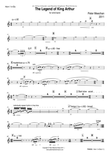
PIPINGPiping Symbol Legendcirculator(w/ isolation flanges)pressure reducing valvecirculator w/integral flow check)diff. pressure bypassgate valveglobe valveanti-scald ratedmixing valveball valvepressure gaugeswing-check valve4-way motorizedmixing valveflow-check valvespring-loaded check valve3-way motorizedmixing valveMunchkin heaterhose bib / boiler drainpressure relief valvethermostatic radiator valveTRV (straight)backflow preventerthermostatic radiator valveTRV (angle)float -typeair ventcircuit setterT/Ptemperature /pressure gaugeunionmanual 3-way valvezone valveheat exchangerair separatorvacuum breakerdiaphragm-typeexpansion tankradiant manifold18Super Storindirect DHW tank
PIPINGCAUTIONCAUTIONThis drawing is to show the Vision contractor the correct installationguidelines. If the Vision 2 is applied to an installation that requires uniquepiping or wiring, it is recommended that you contact your local distributor.These drawings are for reference purpose only. It is important thatinstallers take special notice to the notes located under each drawing thathighlight important installation practices.Sensitive floor coverings shouldhave additional protection with theuse of limiting devices that willshutdown the circulators on thefeed lines to these floors, shouldthere be a failure.Munchkin Vision 1 & Vision 2 control systems4 individual space heating temperaturesPriority domestic water heatingDrawing V2-1Vision 2 valve actuator3-way mixing valve bodyREFER TONOTE 13mixedzone2mixedzone3REFER TO NOTE 13REFER TONOTE 13mixedzone4mixedzone1make-up d mixing valveDHWtemperaturesensor4 3 2 1Vision oilerVision 1 systemT/PP2purgeDHWzoneSuper Storindirect DHW tankthermal trap(w/ drain plug)condensatedrainNOTES:1.This drawing is meant to show system piping concept only. Installer is responsible for all equipment & detailing required by local codes.2.All closely spaced tees shall be within 4 pipe diameter center to center spacing.A minimum of 6 pipe diameters of straight pipe shall be installed upstream and downstream of all closely spaced tees.3.The minimum pipe size for connecting a Super Stor water heater is 1 inch.4.The minimum pipe size for connecting a Munchkin boiler shall be no smaller than the units connection size on supply & return piping.5.6.Some circulators are shown with isolation flanges and integral flow check valves.The alternative is standard flanges with full port ball valves and a separate flow check valve.7.The anti-scald mixing valve is recommended if the DHW temperature is set above the factory setting of 119 F.Install a minimum of 12 diameters of straight pipe upstream of all circulators.8.A purging valve may be used in lieu of the ball valve / hose bib combination shown.9.10. Size header piping so flow velocity does not exceed 4 ft/second under design load flow conditions11. DHW may be controlled as a priority load by setting dip switch #4 on the Vision 2 controller to the "on" position.12. DHW temperature may be sensed by either a mechanical aquastat or thermistor sensor (supplied).13. Note: The 3-way mixing valve shown in this detail reflects the Honeywell application and flow direction. See the detail in the Piping Symbol Legendfor the flow direction for the Belimo valve.19
PIPINGCAUTIONCAUTIONThis drawing is to show the Vision contractor the correct installationguidelines. If the Vision 2 is applied to an installation that requires uniquepiping or wiring, it is recommended that you contact your local distributor.These drawings are for reference purpose only. It is important thatinstallers take special notice to the notes located under each drawing thathighlight important installation practices.Sensitive floor coverings shouldhave additional protection with theuse of limiting devices that willshutdown the circulators on thefeed lines to these floors, shouldthere be a failure.Drawing V2-2Munchkin Vision 2 control systemTwo individual space heating temperaturesDomestic water heatingSub-zoning using zone valvessubzonethermostatsmulti-zonerelay centersubzonethermostatsVision 2 valve actuator3-way mixingvalve bodymixedzone 1sub-zone 2REFER TONOTE 15sub-zone 1sub-zone 3sub-zone 2sub-zone 1multi-zonerelay centermixedzone 2purgemake-up waterpurgecoldwaterpurge4321anti-scaldmixing valveLNG4 3 2 11 2 3 4Vision 2controller1234outdoortemperaturesensorP1Munchkin boilerT/PDHWzoneSuper Storindirect DHW tankcondensatedrainNOTES:This drawing is meant to show system piping concept only. Installer is responsible for all equipment & detailing required by local codes.1.All closely spaced tees shall be within 4 pipe diameter center to center spacing.2.A minimum of 6 pipe diameters of straight pipe shall be installed upstream and downstream of all closely spaced tees.3.The minimum pipe size for connecting a Super Stor water heater is 1 inch.4.The minimum pipe size for connecting a Munchkin boiler shall be no smaller than the units connection size on supply & return piping.5.Some circulators are shown with isolation flanges and integral flow check valves.6.The alternative is standard flanges with full port ball valves and a separate flow check valve.The anti-scald mixing valve is recommended if the DHW temperature is set above the factory setting of 119 F.7.Install a minimum of 12 diameters of straight pipe upstream of all circulators.8.A purging valve may be used in lieu of the ball valve / hose bib combination shown.9.10. Size header piping so flow velocity does not exceed 4 ft/second under design load flow conditions11. DHW may be controlled as a priority load by setting dip switch #4 on the Vision 2 controller to the "on" position.12. DHW temperature may be sensed by either a mechanical aquastat or thermistor sensor (supplied).13. Sub-zoning is accomplished by using zone circulators and multi-zone relay centers.14. The Vision 2 controller can operate up to 4 mixing valves.15. Note: The 3-way mixing valve shown in this detail reflects the Honeywell application and flow direction. See the detail in the Piping Symbol Legendfor the flow direction for the Belimo valve.20
PIPINGCAUTIONCAUTIONThis drawing is to show the Vision contractor the correct installationguidelines. If the Vision 2 is applied to an installation that requires uniquepiping or wiring, it is recommended that you contact your local distributor.These drawings are for reference purpose only. It is important thatinstallers take special notice to the notes located under each drawing thathighlight important installation practices.Sensitive floor coverings shouldhave additional protection with theuse of limiting devices that willshutdown the circulators on thefeed lines to these floors, shouldthere be a failure.Munchkin Vision 2 control systemTwo individual space heating temperaturesDomestic water heatingSub-zoning using zone circulatorszonethermostatsDrawing V2-3multi-zonerelay centerzonethermostatsmulti-zonerelay centersub-zone 3sub-zone 2sub-zone 2sub-zone 1sub-zone 1REFER TONOTE 15mixedzone 2mixedzone 3purgemake-up waterpurgecoldwaterpurge4321anti-scaldmixing valveLNG4 3 2 11 2 3 4Vision 2controller1234outdoortemperaturesensorMunchkin boilerT/PDHWzoneSuper Storindirect DHW tankcondensatedrainNOTES:This drawing is meant to show system piping concept only. Installer is responsible for all equipment & detailing required by local codes.1.All closely spaced tees shall be within 4 pipe diameter center to center spacing.2.A minimum of 6 pipe diameters of straight pipe shall be installed upstream and downstream of all closely spaced tees.3.The minimum pipe size for connecting a Super Stor water heater is 1 inch.4.The minimum pipe size for connecting a Munchkin boiler shall be no smaller than the units connection size on supply & return piping.5.Some circulators are shown with isolation flanges and integral flow check valves.6.The alternative is standard flanges with full port ball valves and a separate flow check valve.The anti-scald mixing valve is recommended if the DHW temperature is set above the factory setting of 119 F.7.Install a minimum of 12 diameters of straight pipe upstream of all circulators.8.A purging valve may be used in lieu of the ball valve / hose bib combination shown.9.10. Size header piping so flow velocity does not exceed 4 ft/second under design load flow conditions11. DHW may be controlled as a priority load by setting dip switch #4 on the Vision 2 controller to the "on" position.12. DHW temperature may be sensed by either a mechanical aquastat or thermistor sensor (supplied).13. Sub-zoning is accomplished by using zone circulators and multi-zone relay centers.14. The Vision 2 controller can operate up to 4 mixing valves.15. Note: The 3-way mixing valve shown in this detail reflects the Honeywell application and flow direction. See the detail in the Piping Symbol Legendfor the flow direction for the Belimo valve.21
PIPINGCAUTIONCAUTIONThis drawing is to show the Vision contractor the correct installationguidelines. If the Vision 2 is applied to an installation that requires uniquepiping or wiring, it is recommended that you contact your local distributor.These drawings are for reference purpose only. It is important thatinstallers take special notice to the notes located under each drawing thathighlight important installation practices.Sensitive floor coverings shouldhave additional protection with theuse of limiting devices that willshutdown the circulators on thefeed lines to these floors, shouldthere be a failure.Munchkin Vision 2 control systemTwo boilers controlled in modulating stagesTwo individual space heating supply temperaturesDomestic water heatingSub-zoning using circulatorsDrawing V2-4zonethermostatsmulti-zonerelay centerzonethermostatsmulti-zonerelay centersub-zone 3sub-zone 2sub-zone 2sub-zone 1sub-zone 1REFER TONOTE 16mixedzone 2mixedzone 13-way mixing valve bodyVision 2 PWM valve actuatorpurgemake-up waterpurgepurge4321LNGcoldwater4 3 2 11 2 3 4Vision ixing valveVision nsorT/PT/PDHWzoneSuper Storindirect DHW tankboiler 1boiler 2condensatedisposalNOTES:1. This drawing is meant to show system piping concept only. Installer is responsible for all equipment & detailing required by local codes.2. All closely spaced tees shall be within 4 pipe diameter center to center spacing.3. A minimum of 6 pipe diameters of straight pipe shall be installed upstream and downstream of all closely spaced tees.4. The minimum pipe size for connecting a Super Stor water heater is 1 inch.5. The minimum pipe size for connecting a Munchkin boiler shall be no smaller than the units connection size on supply & return piping.6. Some circulators are shown with isolation flanges and integral flow check valves.The alternative is standard flanges with full port ball valves and a separate flow check valve.7. The anti-scald mixing valve is recommended if the DHW temperature is set above the factory setting of 119 F.8. Install a minimum of 12 diameters of straight pipe upstream of all circulators.9. A purging valve may be used in lieu of the ball valve / hose bib combination shown.10. Size header piping so flow velocity does not exceed 4 ft/second under design load flow conditions11. DHW may be controlled as a priority load by setting dip switch #4 on the Vision 2 controller to the "on" position.12. DHW temperature may be sensed by either a mechanical aquastat or thermistor sensor (supplied).13. Sub-zoning is accomplished by using zone circulators and multi-zone relay centers.14. Vision 2 controller can operate up to 4 mixing valves.15. Vision 3 controller can operate up to 8 Munchkin boilers.16. Note: The 3-way mixing valve shown in this detail reflects the Honeywell application and flow direction. See the detail in the Piping Symbol Legend for theflow direction for the Belimo valve.22
REFER TO NOTE 16 22 PIPING Drawing V2-4 NOTES: 1. This drawing is meant to show system piping concept only. Installer is responsible for all equipment & detailing required by local codes.


![Merlin@home Transmitter [RF] [symbol update] [RED comp .](/img/10/7bd6c35e-42f6-4c21-be52-037b05000831.jpg)