Transcription
JRRDVolume 51, Number 9, 2014Pages 1411–1426Design and development of solar power-assisted manual/electricwheelchairChi-Sheng Chien, MD;1 Tung-Yung Huang, PhD;2 Tze-Yuan Liao, PhD;3 Tsung-Yuan Kuo, PhD;2* Tzer-MinLee, PhD41Department of Orthopedics, Chimei Foundation Hospital, and Department of Electrical Engineering, Southern Taiwan University of Science and Technology, Tainan, Taiwan; 2Department of Mechanical Engineering, Southern TaiwanUniversity of Science and Technology, Tainan, Taiwan 3Department of Materials Engineering, National Cheng KungUniversity, Tainan, Taiwan; 4Institute of Oral Medicine, National Cheng Kung University, Tainan, TaiwanAbstract—Wheelchairs are an essential assistive device formany individuals with injury or disability. Manual wheelchairsprovide a relatively low-cost solution to the mobility needs ofsuch individuals. Furthermore, they provide an effective meansof improving the user’s cardiopulmonary function and upperlimb muscle strength. However, manual wheelchairs have agross loss of mechanical efficiency, and thus the risk of userfatigue and upper-limb injury is increased. Electric-poweredwheelchairs reduce the risk of injury and provide a more convenient means of transportation. However, they have a largephysical size and are relatively expensive. Accordingly, thepresent study utilizes a quality function deployment method todevelop a wheelchair with a user-selectable manual/electricpropulsion mode and an auxiliary solar power supply system.The auxiliary solar power supply increased the travel range ofthe wheelchair by approximately 26% compared with that of awheelchair powered by battery alone. Moreover, the wheelchair has a modular design and can be disassembled and foldedfor ease of transportation or storage. Overall, the presentresults suggest that the proposed wheelchair provides an effective and convenient means of meeting the mobility needs ofindividuals with mobility difficulties.INTRODUCTIONThe elderly face many physical challenges, includingnerve and muscular degeneration, reduced motor functionand balance, impaired mobility, and so on. Thus, thewheelchair is considered an essential assistive device forimproving the mobility, living quality, and dignity of theelderly and those with mobility difficulties arising fromphysical disabilities, accident-related injuries, and so on [1].Generally speaking, existing wheelchairs can be categorized as either manual, electric-powered, or power-assisteddepending on their mode of propulsion. Traditional manualwheelchairs (MWs) induce a greater oxygen consumptionand a higher respiratory exchange ratio and are thereforeAbbreviations: CG center of gravity, CR customerrequirement, DC direct current, DR design requirement,EPW electric-powered wheelchair, HOQ house of quality,ISO International Organization for Standardization, LED light-emitting diode, MW manual wheelchair, PAPAW pushrim-activated power-assist wheelchair, QFD qualityfunction deployment, rpm revolutions per minute.*Address all correspondence to Tsung-Yuan Kuo, PhD;Department of Mechanical Engineering, Southern TaiwanUniversity of Science and Technology, Tainan 710, Taiwan,R.O.C.; 886-6-2533131, ext 3000; fax: 886-6-3010069.Email: RRD.2013.11.0250Key words: disassemble, electric operation mode, electricwheelchair, manual operation mode, manual wheelchair,mobility assistive device, power-assisted wheelchair, QFD,quality function deployment method, solar power.1411
1412JRRD, Volume 51, Number 9, 2014beneficial to the user’s health when properly used. However, the gross mechanical efficiency of such wheelchairs(i.e., the ratio of the external power to the metabolic power)is just 2 to 13.8 percent, depending on the level of injury,the propulsion technique, the adjustments made to thewheelchair interface (e.g., the seat height), and the intensityof the exercise undertaken [2–9]. This low mechanical efficiency, coupled with the high physical strain imposed onthe movements of the user, may result in fatigue or evenstrain-induced injuries in the worst-case scenario [10–12].As a result, the design and development of electric-powered wheelchairs (EPWs) or power-assisted wheelchairshas attracted increasing attention in recent decades [13–14].Compared with MWs, EPWs have several importantadvantages, including a reduced user effort and a lowerrisk of strain-induced injuries [1,15–22]. Consequently,EPWs have gained in popularity and importance in recentyears and have prompted an increasing number of usersto switch from manual propulsion to motor-powered propulsion [13]. However, present EPWs still have manydisadvantages, including a long charging time, a largephysical size, a heavy weight, and a high expense. Furthermore, most EPWs are inconvenient to maintainbecause of their many mechanical and electrical components. In addition, they cannot be easily folded or disassembled and are therefore cumbersome to store andtransport [13,15–22]. Consequently, their market share isnot yet as much as that of traditional MWs.Wheelchairs that use a combination of human powerand electric power have been developed recently, such aspushrim-activated power-assist wheelchairs (PAPAWs)[13–14]. The human power is delivered by the arms’action on the pushrims, while the electric power from abattery is delivered by an electric motors’ torque. A typical PAPAW can sense the torque on the pushrim to generate proper assist torques by motors. The PAPAW can helpits user maintain physical condition because the risk ofpain and injuries to the upper limbs is greatly reduced.However, the tuning of a PAPAW may be a challenge forindividual users because of the strong dependence uponthe user’s interaction.The motors used to drive electric wheelchairs run onbatteries. As a result, they have a relatively limited travelrange and require frequent recharging. Various researchers have investigated the feasibility of overcoming theselimitations by fitting the wheelchair with a solar powersupply [23–26]. However, to the best of the authors’knowledge, only one published patent currently exists fora solar power-assisted electric wheelchair [23]. In theirdesign, the solar panel is fixed rigidly to the back of thewheelchair by a metal frame and cannot be disassembledat will. Moreover, the wheelchair can only be operated inan electric mode, and thus the potential benefits of thewheelchair as an exercise device are lost. Melanson [24]and Messenger [25] have also proposed the integration ofa solar panel with an EPW. However, both designs suffermany of the same disadvantages as a traditional EPW,including a large physical size, a heavy weight, and a lackof foldability. Curram et al. recently developed a solarpowered wheelchair in which the weight was reduced bymodifying the main frame structure [26]. However, thewheelchair cannot be manually propelled and neither theframe nor the solar power module is foldable.To overcome the limitations of the wheelchairsdescribed, the present study aimed to design and developa solar power-assisted electric wheelchair featuring aswitch enabling the user to choose between manual andelectric propulsion mode and a quick release mechanismfor the batteries and solar panels such that the chair canbe disassembled and collapsed for ease of storage andtransportation.METHODSQuality Function DeploymentThe proposed wheelchair was designed using a quality function deployment (QFD) approach. Generallyspeaking, QFD involves the translation of customerneeds into design requirements or engineering characteristics, which are then transformed into process plans andproduction requirements [27–31]. The first step in theQFD approach is to confirm “who” the users and professionals are, “what” they need, and “how” these needs canbest be met. In the present study, the users were elderly ordisabled individuals. Having identified the customerrequirements (CRs), we applied a statistical approach tothe questionnaire response data in order to assign adegree of importance to each CR by means of a weighting factor with a value ranging from 5 (“very important”)to 1 (“not important”). The relationships between theCRs and the design requirements (DRs) could beexpressed in the form of a house of quality (HOQ) matrixsuch as that shown in Table 1 [32–33].In the QFD approach, the DRs reflect the users’ needsand preferences for the design product (a wheelchair in
1413CHIEN et al. Solar power-assisted wheelchairTable 1.Typical house of quality matrix with 5–3–1 rating scheme.Design Requirements1234CustomerRequirements12345Absolute WeightingRelative Weighting 37130.140.41 230.26 170.19Weighting32451——R strong relationship 5, medium relationship 3, weak relationship 1.the present case) and indicate the particular features of thedesign that the designers must address if customer satisfaction and market success are to be achieved. In the present study, the DRs were identified by a crossfunctionalteam comprising wheelchair engineers, industrial designers, therapists, and clinicians. Note that the strengthweightings were assigned by the design team in accordance with the relationship between the CRs and the DRs.Finally, absolute and relative weighting values wereassigned to each DR, as shown in the lower rows ofTable 1. For each DR, the absolute weighting value wascomputed as Equation 1:mAI j Wi Rij ,1 m ,(1)i 1where AIj is the absolute weighting rating of DRj, j 1, ,n; Wi is the weighting value assigned to CRi, i 1, ,m; and Rij is the weighing value describing thestrength of the relationship between CRi and DRj [31].The relative weighting rating, RIj, was then calculated asEquation 2:RI j AI j,1 n .n AIk 1Travel RangeThe maximum theoretical travel range of the prototype wheelchair was computed using the energy consumed over the experimental tract accompanied by themeasurement of the depletion of a fully charged batterywith a known capacity as exhibited by Equation 3:(2)C DE 1000,(3)where R is the theoretical maximum driving range (inkilometers) given a full battery capacity, C is the batterycapacity (in ampere-hours), D is the distance of the testing track (in meters) 20, and E is the amount of currentconsumed during the test (in ampere-hours).The performance of the prototype wheelchair wasevaluated both with and without the solar panel moduleattached to the power supply system. In order to ensurethe reliability of the test results, the test was done by anondisabled subject. The test procedure was conductedbetween the hours of 10 a.m. and 12 p.m., with an average measured sunlight intensity of 850 W/m2.Static Stability TestThe static stability of the wheelchair was tested inaccordance with the International Organization for Standardization (ISO) 7176–1 standard [35]. Specifically, thewheelchair was secured on a platform using restrainingstraps positioned in such a way as to avoid interferingwith the tipping movement. A 100 kg dummy was placedin the wheelchair and the angle of the platform was thenslowly adjusted until the angle was found at which thechair tipped. The stability of the occupied wheelchair wascharacterized by three variables: (1) the forward tip-overangle, (2) the rearward tip-over angle, and (3) the lateraltip-over angle.RESULTSkSolar Power System EvaluationThe performance of the solar power system in theproposed wheelchair was evaluated based on the statistical results obtained for a 5 kW solar power system givenan annual average effective daily sunshine exposure of3.44 h in Tainan, Taiwan [34].Quality Function Deployment Analysis ResultsThe CRs for the wheelchair were determined bymeans of a questionnaire distributed to 40 users (24 male,16 female, average age 31.5 10.5 yr, average weight68.3 11.1 kg, average height 167.5 7.2 cm, all using awheelchair as their primary means of mobility within thecommunity). The HOQ matrix for the solar powerassisted manual/electric wheelchair is shown in Table 2.
1414JRRD, Volume 51, Number 9, 2014The CRs comprise a total of 13 subitems and are dividedinto three main groups: functional requirements, ergonomic requirements, and interface requirements. Notethat the weighting (i.e., degree of importance) of each CRis shown in the right-most column of Table 2. The DRsare grouped into four categories, dimensions, safety, partcharacteristics, and others, and include such items as theweight, operation functions, collapsing steps, travelrange, and assembling time. The relationships betweenthe CRs and DRs are moderated using weighing factorswith values of 1, 3, or 5, representing a “weak relationship,” a “medium relationship,” and a “strong relationship,” respectively.Generally speaking, a larger value of RIj indicates thatthe corresponding DR is a more critical design requirement. Thus, in the present study, “operation functions,”“travel range,” and “assembling time” were identified ascritical DRs. In completing the QFD design process, adesign goal (target) was assigned to each DR (critical orotherwise) by the design team in accordance with theQFD analysis and the findings of previous studies.Conceptual DesignFigure 1 presents a schematic illustration of the prototype manual/electric wheelchair developed in the present study. For ease of assembly and retraction, thewheelchair is based on the frame of a commerciallyavailable, manually propelled chair (KM-8520, KangYang Hardware Enterprise Co Ltd; New Taipei City,Taiwan). Moreover, an electric propulsion capability isachieved by means of a battery set (the main powersource) and two electric motors (one motor per drivenwheel). The travel range of the wheelchair is extendedvia the use of a solar panel auxiliary power supply. Asshown in Figure 1, the solar panel is installed in such away as to provide a roof over the user’s head, therebyacting not only as a secondary power source but also as ashelter against the sun and rain. Importantly, theTable 2.House of quality correlation matrix for solar power-assisted manual/electric wheelchair.Design RequirementCustomer RequirementBasic rParts CharacteristicOperationFunctionsBatteryPart velRangeAssembling AppealingTimeOutlookCostCapabilityFunctional RequirementsCollapsible Easy to Use Capable of Long Travel RangeCapable of Decelerating and BrakingCapable of Pirouetting 5 4 51 4 Ergonomics RequirementsErgonomics High Mobility Comfort Self-Maneuverability Rain Shelter2 5 4 4 3Interface RequirementsConvenient Maintenance Design Safety Large Battery Capacity 1 4 5087 559629100ImportanceAbsolute WeightingRelative Weighting (%)Target45437.16.8Retain 40 kgstandard manual specs60965443749.515.38.66.88.013.811.8Protects As easy Minimize Minimize As short As far As easy as user as possibleas possible as possible possibleeffectively strong relationship 5, medium relationship 3, weak relationship 1.182.99.4As soft As low as possible as possible—
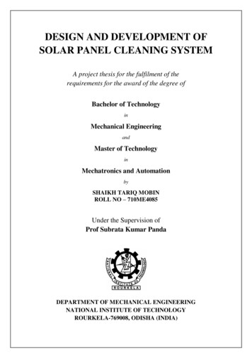
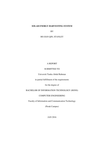
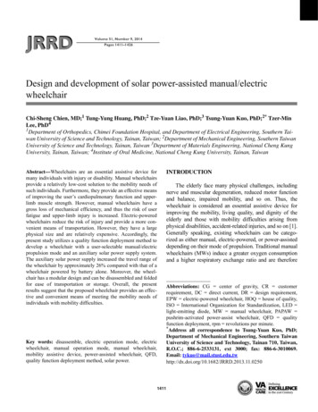
1415CHIEN et al. Solar power-assisted wheelchairPrototype WheelchairFigure 3 presents a photograph of the prototypewheelchair. The basic specification details of the wheelchair are provided in Table 3. As stated previously, thewheelchair is based on the frame of a commerciallyavailable manual wheelchair and has a weight of 17.4 kg.The auxiliary components of the wheelchair, e.g., thesolar panels, battery set, and planetary gears, have a combined weight of 21.6 kg. Thus, the wheelchair has a totalweight of approximately 39 kg. Figure 4 illustrates theplanetary gear set used in the proposed wheelchair as adeceleration mechanism and a switching componentbetween the manual driving mode and the electric drivingmode. The major modules of the proposed wheelchair arebriefly described in the following sections.Figure 1.Conceptual design of solar power-assisted manual/electricwheelchair proposed in present study. (1) Solar panel (singlecrystal, 60 W), (2) foldable frame for solar panel, (3) steeringjoystick and controller, (4) manual/electric mode switch,(5) quick release for solar panel’s frame, (6) wheelchair handle,(7) batteries, (8) motor (50 W 2), (9) planetary gear.wheelchair is fitted with a manually operated clutchmechanism enabling the user to change at will between amanual propulsion mode and an electric propulsionmode. Finally, the solar panel assembly is based on amodular design and is equipped with “quick release”mechanisms in order to enable the chair to be collapsedand folded for storage and transportation purposes.Figure 2 presents the electric circuit of the proposedwheelchair. As shown, the battery and solar panel areconnected in parallel, with a diode placed between themin order to prevent a reverse flow from the battery to thesolar cells. In the electric propulsion mode, the battery(or solar cell) supplies power to a control unit, whichissues commands to drive the motors of the two wheels inaccordance with the direction and velocity inputs provided by the user through a hand-activated joystick.MotorsIn general, EPWs should carry the user at a speed nogreater than the prescribed speed limit (6–12 kmh 1 inmost countries) and should be capable of carrying anindividual with a weight of 90 kg not only on flat groundbut also on 7 (corresponding to a slope gradient of 1:8)uphill ramps. Note that the Americans with DisabilitiesAct recommends a 1:12 slope, which is around 4.8 [36].Most direct current (DC) motors rotate at hundreds tothousands of revolutions per minute (rpm) and are therefore unsuitable for driving the standard 24 in. diameterwheels of a wheelchair directly. Furthermore, while gearmotors have a built-in reduction gear set, the reductionratio is insufficient to meet the low speed requirements ofa wheelchair. Thus, the prototype wheelchair developedin the present study was fitted with a planetary gear set inorder to reduce the speed of the chair and increase thetorque supplied to the wheels. The electric propulsionmode was provided by two 3MEN BL5S brushless DCgear motors driven by 3MEN BL300–0 brushless DCdrivers (3MEN Technologies; New Taipei City, Taiwan).The rated speed and torque of the chosen gear motorswere 2,700 rpm and 0.19 Nm 1, respectively. Meanwhile,the reduction ratio of the planetary gear set was specifiedas 5.31 (gear ratio 85/16) in order to limit the speed ofthe wheelchair to a range of 3 to 7 kmh 1 (i.e., 2π 12 0.0254 2,700 60/1000/5.31 7.6 kmh 1). The planetary gear set provides an improved uphill-climbing capability and a better downhill-braking capability when thewheelchair is operated in the electric mode. (Note that the
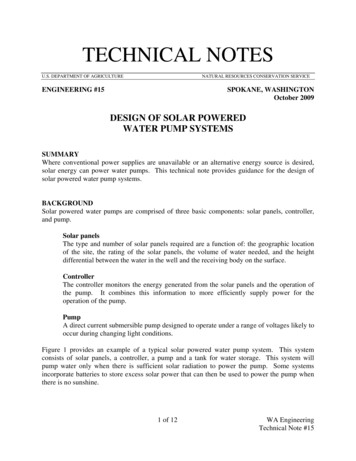
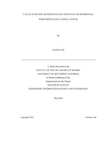
1416JRRD, Volume 51, Number 9, 2014Figure 2.Electric circuit of prototype of solar power-assisted manual/electric wheelchair. M motor.Table 3.Detailed specification of solar power-assisted manual/electric wheelchair.ItemContour DimensionMinimum Turning RadiusAddition Extra WeightSolar PanelsDriving HardwareManual Wheelchair WeightNet WeightMaximum LoadFront Wheel Specifications ( 2)Rear Wheel Specifications ( 2)Motor VoltageMotor Power ( 2)Battery ( 2)Chargers InputParameter1050 610 870 mm650 mm21.6 kg8 kg13.6 kg17.4 kg39 kg130 kg8 in.24 in.24 V (DC)100 WLead-acid battery12V/12Ah, AC 110V/AC220VAC alternating current, DV direct current.Figure 3.Photograph of prototype of solar power-assisted manual/electric wheelchair.climbing and braking capabilities are made possiblethrough the interaction between the motor and the gears.)Power SourcesThe main power supply for the wheelchair was provided by two 12VDC (12Ah) YUASA (YTX14-BS,Taiwan Yuasa Battery Company; New Taipei City, Taiwan) rechargeable lead-acid batteries connected in series.In addition, the wheelchair was fitted with a solar panelas an auxiliary power supply. When the wheelchair isoperated in the electric mode, the driving power is provided by both the batteries and the solar power supply,with the contribution of the solar panel being determinedby the sunlight intensity and the residual battery voltage.Moreover, when operated in the manual mode or stopped
1417CHIEN et al. Solar power-assisted wheelchairFigure 4.Schematic illustration of manual/electric mode switch mechanism.Solar Panel ModuleAs described previously, the battery set used as themain power supply for the wheelchair has a total outputvoltage of 24 VDC. Accordingly, in selecting the auxiliarypower supply, a solar panel module with a power of 60 Wand a nominal voltage of 24.5 V was chosen. The solarpanel had dimensions of 540 620 mm and a conversionefficiency of the single crystalline silicon solar panelmodule is 15 percent. The I-V and P-V curves (Figure 5)show that the maximum efficiency of the solar panel isobtained at an output voltage of around 7 V. Furthermore,the test results indicated that the 60 W solar power module was capable of generating 206.4 Wh every day, equalto 13.76 Ah for a 12 V battery with an efficiency ofaround 80 percent.In order to improve the solar power conversion efficiency, the solar panel was mounted on the wheelchairusing an angular adjustment mechanism comprising alocation pin, a spring, and a series of positioning holes(Figure 6).under the sun, the solar power system charges the batteryset for later use. The simulated I-V (current vs voltage) P-V(power vs voltage) characteristics of each of the solarcells in the solar panel are shown in Figure 5. The maximum current that the solar panel can provide is around2.45 A (60 W / 24.5 V 2.45 A).Manual/Electric Mode SwitchIn the proposed wheelchair, a power drive moduleand mechanical clutch mechanism are used to facilitateboth a manual driving mode and an electric drivingmode. The change between the two driving modes ismade by using a switch rod to engage the driven gearwith the driving gear (electric mode) or disengage theFigure 5.Simulated characteristic curves of solar cell.
1418JRRD, Volume 51, Number 9, 2014Figure 6.Angle adjustment component of solar panel module: (a) schematic illustration, (b) photograph, and (c) folded solar panel.driven gear from the driving gear (manual mode). (Notethat the mechanism design has been patented [37].) Figure 7 shows the detailed components of the switch mechanism. Changing between the two driving modes requiresthe application of a force of just 20 N to the handleattached to the switching rod (Figure 4).Steering Joystick and ControllerThe steering module comprises a hand-activated joystick and a controller (within a box) mounted on the armrest of the wheelchair, as shown in Figure 8. Through theuse of the joystick, the wheelchair can be controlled tomove in a straight line in the forward or reverse direction,to turn left, or to turn right. The proposed wheelchair usestwo motors to power the drive wheels and has a differential steering capability similar to that of EPWs. As aresult, the wheelchair is capable of pirouetting.Battery Monitor and LED TaillightsIn general, the life of rechargeable batteries is shortened by excessive discharging and overcharging. However, by force of habit, most users charge theirwheelchairs every night such that the batteries are fullycharged in the morning. Nonetheless, a voltmeter waspositioned in front of the hand-activated joystick in orderto provide an indication as to the amount of battery liferemaining (Figure 8). In addition, two light-emittingdiodes (LEDs) were mounted on the rear of the seat to actas taillights (Figure 3).Quick Release MechanismsThe prototype wheelchair was built around the mainframe of a commercial foldable MW. The various components and modules of the wheelchair were attached tothe main frame by means of quick-release fasteners,thereby enabling the chair to be disassembled and collapsed for ease of storage or transport (Figure 9). Boththe solar panel and the battery set must be removed fromthe frame before the chair can be collapsed and folded.Thus, compared with traditional MWs, the disassemblyprocess takes longer and requires the assistance of a nondisabled individual. However, compared with mostEPWs, which require a van or specially designed vehicleto transport the wheelchair, the convenience offered bythe proposed chair in being able to be transported in aregular car is regarded as a major advantage.TestsTravel RangeThe maximum travel range of the wheelchair wastested with and without the solar power module attachedto the power supply system. The wheelchair was fittedwith a lead-acid battery set of 24V/12Ah, and the combined weight of the user and the wheelchair was 114 kg(wheelchair: 39 kg, user: 75 kg). In the test procedure,the user was asked to complete 20 laps of a 100 m trackat an average speed of 2 kmh 1. Note that this speed was
1419CHIEN et al. Solar power-assisted wheelchairTable 4.Static tip-over angles (in degrees) of proposed wheelchair, EPWs andMWs [39–40].WheelchairProposed WheelchairEPWE&J LanserQuickie P200Invacare StormPride JazzyPermobil ChairmanMean ValueMWTiLite AeroZInvacare GrossfireQuickie GTKuschall AirProMean 1920.5EPW electric-powered wheelchair, MW manual wheelchair.Figure 7.Photographs of manual/electric mode switch mechanism:(a) switching rod, (b) connecting linkage, and (c) planetary gears.specified in accordance with the average travel speed ofan individual driving a conventional EPW [38]. The testresults showed that the current consumption was 1.42 Ahusing the solar power supply and 1.79 Ah using thebattery set alone. The travel range was computed usingan 80 percent battery capacity as the benchmark. Thus,from Equation 3, the maximum theoretical travel rangewas calculated to be 13.52 km and 10.72 km with andwithout the solar power supply, respectively. In otherwords, the solar panel increased the maximum travelrange of the wheelchair by approximately 26 percent(i.e., (13.52–10.72)/10.72 100% 26%).Static StabilityFigure 10 presents two photographs of the static stability test configuration. The results of the stability testsare shown in Table 4. All three angles significantlyexceed the value of 7 specified by the ISO 7176–1 standard [35]. Thus, the static stability of the proposedwheelchair is confirmed. The tipping angle of severalmainstream EPWs and MWs [39–40] are also shown inTable 4. It is clear that the static stability varies with different wheelchairs. Compared with the EPWs and MWs,the tip-over angles of the proposed wheelchair in the forward and rearward orientation are the middle values inthe corresponding columns, while the angle is larger thanthe middle value in the lateral orientation. In the stabilitytest, the larger the tip-over angle is, the more stable thewheelchair is. Thus, it can be concluded that the staticstability of the proposed wheelchair is either average orbetter than the average.DISCUSSIONTravel RangeThe travel range of an EPW is determined by manydifferent factors, including the battery type and size, thebattery state, the combined wheelchair/user weight, theterrain, the efficiency of the drive train, and the drivingbehavior of the user [41]. In the case of the prototype
1420JRRD, Volume 51, Number 9, 2014Figure 9.Photograph of folded prototype wheelchair in car trunk.Figure 8.Steering joystick and controller.wheelchair proposed in this study, the travel range is further affected by such factors as the solar cell efficiency,the sunlight intensity, and the travel speed. The testresults showed that the use of the solar power systemresulted in a 26 percent improvement in the travel range.However, the battery used in the present tests had acapacity of just 12 Ah, i.e., around 3 to 6 times lowerthan that of a commercial EPW battery [42]. Thus, it isreasonable to assume that if the battery in the prototypewheelchair is replaced with a commercial EPW-gradebattery, a more significant improvement in the travelrange can be obtained.The prototype wheelchair was fitted with a conventional lead-acid battery set in order to evaluate the basicfeasibility of the hybrid battery-solar panel power supply.However, as battery chemistry improves, we anticipatethat the lead-acid battery set can be replaced with a lowmaintenance, high-energy-density lithium-ion or lithiumion polymer battery set.Static StabilityThe forward, rearward, and lateral tip-over angles ofthe wheelchair depend on the relationship between theposition of the overall center of gravity (CG) of the chairand its base of support. Specifically, tip over occursunder either static or constant velocity conditions whenthe vertical projection of the combined CG of the wheelchair exceeds a certain angle [43]. In practice, the stability of the wheelchair can be improved by lowering theCG [44–46]. Thus, in the prototype wheelchair, all of themajor components other than the solar panels were positioned beneath the seat in such a way as to lower the CGand move its position to the approximate center point ofthe chair.Effects of Additional MassA previous study reported that the placement of anadditional 5 to 10 kg at the rear wheel or under the seat ofa manual wheelchair has only a minimal effect on thepower output, physical strain, and propulsion time [47–50]. Consequently, the wheeling velocity, percentagepush time [48], energy expenditure, heart rate, and sprinttime [49] showed no significant change. However,another study showed that an additional mass of 9.05 kgresulted in a lower velocity and greater resultant and tangential forces [50]. The difference in the findings regarding the effects of the additional mass is most likely the
1421CHIEN et al. Solar power-assisted wheelchairHowever, in contrast to a conventional MW, the proposedchair is fitted with a mechanism enabling the user toswitch at will between a manual propulsion mode and anelectric mode. Consequently, the chair both helps the userachieve a strengthening of the car
propulsion mode and an auxiliary solar power supply system. The auxiliary solar power supply increased the travel range of the wheelchair by approximately 26% compared with that of a wheelchair powered by battery alone. Moreover, the wheel-chair has a modular design and can be disas