Transcription
Noise Power, Noise Figureand Noise TemperatureMarch 21, 2014Sujeong Lee
Noise Any unwanted input - UNDESIRABLE portion ofan electrical signal Limits systems ability to process weak signals
Noise Power Most of input noise Thermal Noise Noise powerNp kBT BkB Boltzmann s constant 1.38x10 -23 J/KT Absolute temperature of deviceB Circuit bandwidth
Noise Power Signal to Noise Ratio (SNR)S ( f ) average signal powerSNR N ( f ) average noise power
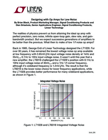
o Soo/No oothe noise figure of the receiver.Noisefigurehas hasnothingto domodulationor urehasnothingtowithdo withwithmodulationor lationformatandof theItisindependentofthemodulationformatandoftion. It is independent of the modulation format andof urefidelity of modulators and demodulators. Noise figure is,is,therefore,a moregeneralconceptthanthannoise-quietingusedto totherefore,aa te the sensitivity of FM receivers or BER used in s.Noise Figure Noise FigureSi/NSSi/Ni ii ――――――――――i/N ―――――――――― ――――――――――GSGS/(N i ii/(Na aaGNi) ii))GS/(N GNGNNaN i iiN aaGN GNGN ―――――― ―――――― GN――――――GNi iiNoisefigureshouldbe thoughtof eNoisefigureshouldbe thoughtthoughtofseparateas al,subsequentgainamplifiessignalnoisenoise isis addedadded toto thethe signal,signal, subsequentsubsequent gaingain amplifiesamplifies signalsignaland andnoisetogetherandanddoesdoesnot notchangethe seratio.availableat theinputto thedeviceuratio.availableat theinputto thedevicrepresentthesignalandnoiselevelsrepresent the signal and noise leFigure1-2(a)showsan examplesituationat theinputof anNa isnoiseaddedby theDUT,anFigure1-2(a)showsan examplesituationat theinputof anNatheis thenoiseaddedby sefloor:DUT.Equation(1-2)showsthedepeamplifier. The depicted signal is 40 dB above the noise floor:DUT. Equation (1-2) shows the deFigure1-2(b)showsthe thesituationat theamplifieroutput.inputNi. Theinputnoiselevelis usuFigure1-2(b)showssituationat theamplifieroutput.inputNi. B. Framplifier’s gain has boosted the signal by 20 dB. It alsosource and is referred to byokToBboostedthe theinputnoiselevellevelby 20thenthenaddedits ownsourcetemperatureof 290K(dboostedinputnoiseby dB20 anddB andaddedits own enceencesourcetemperatureof 290Knoise. The output signal is now only 30 dB above the noiseequivalentto16.8 Cand62.3 F.Thnoise. The output signal is now only 30 dB above the noiseequivalent to 16.8 C and 62.3 Ffloor. Since the degradation in signal-to-noise ratio is 10 dB,average temperature seen by recfloor. Since the degradation in signal-to-noise ratio is 10 dB, the theaverage temperature seen bythe amplifier has a 10 dB noise figure.across the atmosphere at the transmthe amplifier has a 10 dB noise figure.across the atmosphere at the tra Noise figure represents thedegradation in signal/noise66ratio as the signal passesthrough a device.outputinput F is always greater than 1.
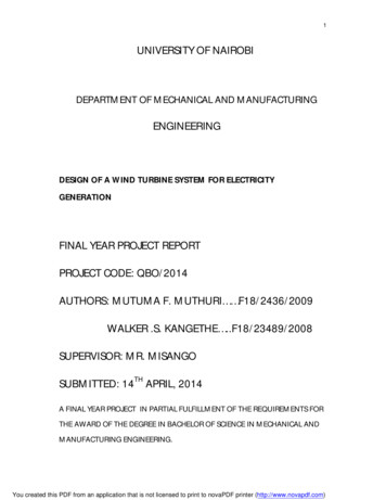
Noise FigureNoise Factor Noise FigureModern usage of “noise figure” usually is reservedfor the quantity NF, expressed in dB units:NF 10 log10 F [dB]NF (Si/Ni)dB – (So/No)dBSo/NoSi /Ni(Si/Ni)dB 40 dB(So/No)dB 30 dBNoise Figure 10 dB
Noise Temperature Comes from the random motion of electrons! Thermal Noise Convenient! Common basis for measuringrandom electrical noise from any source Relation with Noise FigureTe To ( F – 1 )Te : The effective noise temperature of deviceT0 : a reference temperature 290K (room temperature)
Summary Noise Power– The magnitude of NoiseNp kBT B Noise Figure– Noise Factor– Noise Figure : the degradation of SNRNF 10 log10 F [dB] Noise Temperature– Basic tool of measuring any kind of noise– Relation with Noise FactorTe To ( F – 1 )
The concept of noise figure The most basic definition of noise figure came into popular use in the 1940's when Harold Friis [8] defined the noise figure F of a network to be the ratio of the signal-to-noise power ratio at the input to the signal-to-noise power ratio at the output. Thus the noise figure of a network is the decrease or degrada-