Transcription
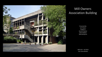
Mill OwnersAssociation BuildingPresented By:Suril GajeraYangzao LiDarrion OrpinelSahar RadwanNeha RampuriaSource - Archdaily websiteARCH 631 - Fall 2019Prof. Anne Nichols
Introduction-Location - Ahmedabad, Gujarat, IndiaArchitect - Le CorbusierClient - Ahmedabad Mill Owners AssociationTimeline - 1954-1956Height 58 ftFloors - 3Source - Maps of India webpageSource - Wikipedia-Temperature - 55 F (min), upto 125 F(max)Climate - hot and semi-aridAnnual Rainfall 31 inchesSource - Google Maps
Site-Elevation – 174ft.Soil Type – Sandy and Dry.Seismic Zone – 3.Figure 1. Bird Eye View ofSiteFigure 2. Site Plan.
Background and Design ConceptCorbusier was invited to India by its first president to designthe capital city of Chandigarh in 1951.This is when he was commissioned by the mayor ofAhmedabad to do five projects in the city which reflects itsfuturistic vision.ATMA House was one of the first ones to get completed.The building design majorly focused on the climate and cultureof the people. Inspired by the local architecture andconsidering immediate context, various design principles werelaid out.Unite d’habitationSource - Foundation Le CorbusierRonchampShodhan VillaSource - www.researchgate.netArchdailyArchdaily
Five Points of Architecture-Raised StructureA free facadeOpen Floor PlanRibbon windowsRooftop GardenSource - Vanny Ang, PinterestThe ModularLe Corbusier explicitly used the Modular to derive his scales andarchitectural proportions.Source - Foundation Le Corbusier
Building Geometry Three Levels Elongated Entrance Rectangular Exterior Organic Interior Shapes
First Floor PlanFigure 3.Figure 7.Figure 4.Figure 8.Figure 5.Figure 9.Figure 11.Figure 6.Figure 10.
Second Floor PlanFigure 12.Figure 16.Figure 13.Figure 17.Figure 14.Figure 18.Figure 20.Figure 15.Figure 19.
Third Floor PlanFigure 21.Figure 22.Figure 23.Figure 24.Figure 25.Figure 26.Figure 29.Figure 27.Figure 28.
Mezzanine Floor PlanFigure 32.Figure 30.Figure 33.Figure 31.Figure 34.Figure 36 .Figure 35.
Special FeaturesCurvilinear Roof-Roof slab is used to linkthe façade structureand the main structure- The roof designed tobe a reproductive roofgardenBracing systemdependent on thefloor heightThe facades haveseparate reinforcementconcrete structurePlanted shelves atfirst and secondfacade floorsAlvaro, Pinterest
Brise Soleil / Sun BreakersFigure 37. January, Sun Breaker at 12:30 pm.Figure 39. July, Sun Breaker at 12:30 pm.Figure 38. April, Sun Breaker at 12:30 pm.Figure 40. October, Sun Breaker at 12:30 pm.
FoundationBecause the soil in this area is dry sandy soil which has limited load bearingcapacity, it is speculated that the strip foundation was used in the design.In the strip foundation, the foundation beam has a large shear, bending andpunching shear resistance, which is suitable for the situation that the load ofthe column is large, and the bearing capacity of the soil layer is low.An example of strip foundationAn example of isolated footing
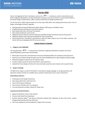
Structural SystemsThis building has a rigid frame - shearing walls structural system, thereare 4 primary shearing walls and 16 secondary shearing walls (bearingonly self weight). The grid span is 24ft*24ft.There is no column at the end span and middle span,so shearing walls were used to act as columns.ColumnsPrimary shearing wallsSecondary shearing walls(bearing only self weight)
Structural SystemsBeam (Single - way)Primary shearing wallsSecondary shearing wallsColumnThis is a one-way beam framestructure, and the rigid floorplates can be regarded as“beams” in the other direction.
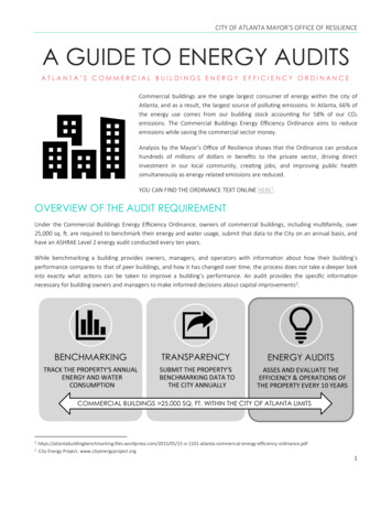
Load Tracing Roof Distribution through anchorsThrough columns and DiaphragmsBrise Soleil Carry little load
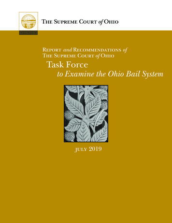
Visual AnalysisFor the first section (figure 1), all the vertical members are circularcolumns, and the horizontal elements are the beams, in the graphs weselected one beam and one column to add its results for the momentshear and deflection as shown in the graphs below.Figure 1
We’ve added fixed nodes at the ground base connection, theprimary structural system consists of beams and columns grid,by applying the dead and live loads on it we got these results inthe graphs below.For the second section (figure 2), the middle three verticalmembers are the circular columns, the shear wall as the area inthe middle, and the members at the edges are the bricksbearing walls, the nodes connections at intersections arepinned.Figure 2
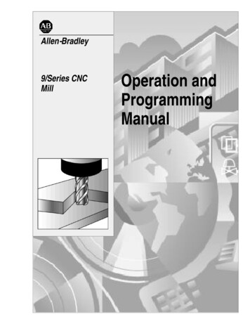
Load transfer in RoofFigures above shows how the load of the curvilinear roof isgetting transferred through the main beams to thefoundations
SummaryThis report is composed of a brief background of Mill Owner’s Association, the city of Ahmedabad ,the Architect - Le Corbusierand how they came together to build this project. ATMA House has become an iconic structure in the history of Architecture inIndia. Not only it is a great example of an artistic design but received appreciation for its structural innovation. Special featureslike the Curvilinear roof and Brise Soleil, as descried in the report, were interesting learning in terms of its structural supportsystem as well as its purpose. Furthermore, load tracing and analysis describes how each member behaves in this system andplays its role in transferring the load to the foundation.Through this structure, the Architect and the engineer have redefined the idea of inside outside. The ceremonial ramp,perforated façade, curvilinear forms and ample open spaces harmonizes with it surrounding and stood out as a bold expressionof modern aesthetic.
ReferencesBuilding CodesFor Load Calculations :-Figure 2, 11, 20, 36. by Author.Figure 3-10; 12-19; 21-28; 30-35; from ATMA Wordpress BlogFigure 37-40 from Google Sketchup Warehouse- Ahmedabad’s Textile Industry and its booming past (2017) - article atVoice by Kunjan Panchal- Mill Owners Association Building Ahmedabad - Wikipedia- #Archifocus: Le Corbusier building in India (2017) - article on Architectby Rima Alsammarae- The Mill Owners Building of Le Corbusier - ATMA Webpage- Mill Owners’ Association Building / Le Corbusier - Archdaily- Foundation Le CorbusierDead Load - IS 875 Part 1Live Load - IS 875 Part 2Wind Load - IS 875 Part 3Earthquake Load - IS 1893For Design :Concrete - IS 456, SP 16 IS Codes 875 - Indian StandardCode of Practice for Design Loads (other than earthquake)for buildings and StructuresIS 1893 - Indian StandardCriteria for Earthquake Resistant Design of StructuresSP-16 - Design Aids for Reinforced Concrete to IS: 456-1978
ATMA House, AhmedabadPresented By:Suril Gajera, Yangzao Li, Darrion Orpinel, Sahar Radwan, Neha Rampuria
Figure 7. Figure 11. First Floor Plan. Figure 15. Figure 14. Figure 13. Figure 12. Figure 19. Figure 18. Figure 17. Figure 16. Figure 20. Second Floor Plan. Figure 27. . Figure 37-40 from Google Sketchup Warehouse - Ahmedabad's Textile Industry and its booming past (2017) - article at Voice by Kunjan Panchal