Transcription
research reportResidential Hip RoofFraming Using Cold-FormedSteel MembersRESEARCH REPORT RP06-22006American Iron and Steel Institute
Residential Hip Roof Framing Using Cold-Formed Steel MembersiDISCLAIMERThe material contained herein has been developed by researchers based on their researchfindings and is for general information only. The information in it should not be used withoutfirst securing competent advice with respect to its suitability for any given application. Thepublication of the information is not intended as a representation or warranty on the part of theAmerican Iron and Steel Institute, Steel Framing Alliance, or of any other person named herein,that the information is suitable for any general or particular use or of freedom frominfringement of any patent or patents. Anyone making use of the information assumes allliability arising from such use.Copyright 2006 American Iron and Steel Institute / Steel Framing Alliance
iiResidential Hip Roof Framing Using Cold-Formed Steel MembersPREFACEThe objectives of this project were to investigate a more rational rafter design methodologyfor both gable and hip roofs and develop all the necessary tables, details and specificationrequirements for hip roof framing members and connections for addition to the AISI Standardfor Cold-Formed Steel framing – Prescriptive Method for One and Two Family Dwellings [PrescriptiveMethod]. This report accomplishes these objectives, provides useful insight and suggests futurestudy topics that should assist in identifying and prioritizing future research needs.It is expected that portions of this report will indeed be incorporated in the PrescriptiveMethod. As such, the results of this work will have a lasting and beneficial impact on the steelframed residential construction industry.Research TeamSteel Framing Alliance
Civil Engineering Study 06-1Cold-Formed Steel SeriesFinal ReportRESIDENTIAL HIP ROOF FRAMING USING COLD-FORMED STEELMEMBERSbyLuke WaldoResearch AssistantSutton F. StephensRoger A. LaBoubeProject DirectorsA Research Project Sponsored by theAmerican Iron and Steel InstituteJuly, 2006Department of Civil EngineeringWei-Wen Yu Center for Cold-Formed Steel StructuresUniversity of Missouri-RollaRolla, Missourii
TABLE OF CONTENTSPagePREFACE41.0 Analysis of Hip Roof System61.1 Analysis Procedure61.1.1 Model Development61.1.2 Results of RISA-3D Analysis101.2 Comparison of Unsheathed and Sheathed Roof Framing Systems1.2.1 Analysis Summary and Comparison12121.3 Conclusions121.4 Recommendations for Further Research132.0 Hip Framing Analysis and Design262.1 General262.2 Loads262.2.1 Dead Loads (D)272.2.2 Roof Live Load (Lr)272.2.3 Roof Snow Load (S)272.2.4 Wind Load (W)272.3 Load Combinations282.4 Hip Member Analysis and Design292.5 Hip Member Support Column292.5.1 Column Above Ceiling302.5.2 Column Support Below Ceiling312
2.6 Connections312.6.1 Hip Member Connection at Ridge322.6.2 Hip Member Connection at Wall Corner332.6.3 Hip Support Column Connection at the Ceiling332.7 Alternate Hip and Ridge Member Configuration342.8 Conclusions35APPENDIX A – DESIGN CALCULATIONS443
PREFACECold-formed steel is continuing to increase in popularity in the residential constructionmarket and is gaining an increasing market share compared with other construction materials.Conventionally framed roof construction uses rafters, ridge members, and ceiling joists and does notinclude any supplemental interior ridge member supports or collar ties between rafters althoughceiling joists may be supported by an interior bearing wall. At hip ends, conventionally framedconstruction uses hip members and jack rafters, and ridge member support braces are alsocommonly used. Section R802.3 of the International Residential Code (ICC 2003) states “Hip andvalley rafters shall be supported at the ridge by a brace to a bearing partition or be designed to carryand distribute the specific load at that point.” Conventional framing has traditionally been used inlight framed wood structures and more recently in roofs framed with cold-formed steel members.The American Iron and Steel Institute developed the Standard for Cold-Formed SteelFraming – Prescriptive Method for One and Two Family Dwellings (AISI 2002). This Standard isuseful for the design of residential projects because it allows standard one and two story residentialstructures to be designed without the services of an architect or structural engineer. The currentedition of the Prescriptive Method, however, does not address the design of the members necessaryto construct hip roofs. Accordingly, the AISI Committee on Framing Standards (COFS) determinedthat research should be carried out to develop all the information necessary to allow for theconstruction of hip roofs using the Prescriptive Method. One of the objectives of this study was toinvestigate a more rational rafter design methodology for both gable and hip roofs. A secondobjective was to develop all the necessary tables, details and specification requirements foradditions to the Prescriptive Method, and the Commentary to the Prescriptive Method for hip roofframing members and connections.4
This report is based mainly on a thesis submitted to the Faculty of the Graduate School ofthe Kansas State University in partial fulfillment of the requirements for the degree of Masters ofScience in Architectural Engineering.Technical guidance for this study was provided by the Steel Framing Alliance’s ProjectMonitoring Task Group (Bill Babich, Nader Elhajj, Steve Fox, Dick Layding, and Steve Walker),and the American Iron and Steel Institute’s Prescriptive Method Subcommittee (Steve Fox,Chairperson). The Project Monitoring Task Group and the Subcommittee’s guidance is gratefullyacknowledged. Appreciation is also extended to Jay Larson, AISI for his guidance and assistance.Partial funding for this study was provided by the American Iron and Steel Institutes. The authorsextend their appreciation to AISI for the financial support.5
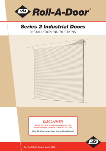
1.0 Analysis of Hip Roof System1.1 Analysis ProcedureThe purpose of this portion of the report is to provide details of a finite element analysis thatwas conducted to investigate the interaction of plywood sheathing with a typical rafter. The goal wasto determine what contribution the sheathing makes in the distribution of forces to other members inthe framing system. The current method of analysis for conventionally framed roof rafters, whetherof wood or cold-formed steel, is to ignore compressive forces and design the rafter for bending only(AFPA 2001a, AISI 2003). Rafters are designed as individual pieces, neglecting any strength andstiffness contribution of the sheathing other than to provide restraint against lateral-torsional buckling.However, a simple two dimensional analysis of the rafter in combination with the ceiling joist and therafter on the opposite side of the ridge to form a truss type framing system, as show in Figure 1.2,shows that a compression force is developed in the rafters. It should also be noted that the lower theslope of the rafter, the greater the axial compression in the rafters.An unsupported hip roof system does not provide direct support, via either columns orbracing, for the hip and ridge members. Because of this, the structural support for these members isprovided by the rafters that frame into them, the ridge member being supported by the side rafters, andthe hip rafters being supported by the jack rafters.1.1.1Model DevelopmentComputer models of two different sloped hip roofs were developed for analysis untilizingRISA-3D (RISA 2005) analysis and design software. Both sheathed and unsheathed models werebuilt. All hip roof systems were analyzed assuming a 32 ft. x 60 ft. rectangular building with a 2 ft.roof overhang around the perimeter of the roof (Figures 1.1 and 1.2). The horizontal rafter span was16 ft. from the centerline of the ridge to the outside face of the wall. The rafters were spaced at 24-6
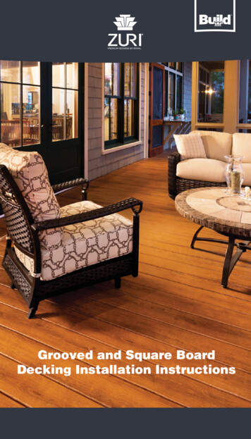
inches on center, the most common spacing for roof rafters. The ceiling joists were also spaced at 24inches and were pinned to the rafter at the top of the wall. Roof slopes of 3:12 and 10:12 wereanalyzed. A 3:12 roof slope is the minimum allowed when using the Prescriptive Method (AISI2003) and 12:12 is the greatest slope allowed. The 10:12 slope model was selected for analysis sinceit was assumed to be more common for high sloped roofs.All members were modeled with simple pin-pin connections. The hip members and ridgemembers were modeled as a built-up section consisting of a C-shape and a track section (Figure 1.3).The hip members and ridge were assumed continuous for their full length. The ceiling joists weresupported at mid-span by an interior bearing wall and were assumed continuous over the interiorsupport. Table 1.1 lists the different member sizes used for analysis of all roof models. The memberdesignations used in the table are in accordance with the Standard for Cold-Formed Steel Framing –General Provisions (AISI, 2004).The perimeter walls were assumed to provide vertical support for gravity load from the roofrafters and ceiling joists. They also were assumed to have sufficient in-plane stiffness to providelateral restraint for the roof and ceiling members in the plane of the wall. The walls were not assumedto provide any lateral support in the out-of-plane direction at the top of the wall for the roof andceiling framing members. The wall itself was not included in the model for analysis; however, thecontinuous top track of the wall was included in the model (Figure 1.4). This member provided a tiein what would be the plane of the wall, just as in an actual structure.The loading applied to all roof framing models were dead and snow loads. The dead loadsapplied were those currently assumed in the Prescriptive Method and taken from Table A1-1. ThePrescriptive Method can be used for snow loads up to 70 psf ground snow load. For this study, a 30psf ground snow load was assumed since it represents a practical maximum for many portions of the7
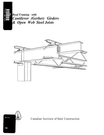
United States. Wind loads were not considered for this study. Figure 1.5 shows the method used forload application to the rafters. A description of the loads used for this study is given as follows:Roof Dead Load7 psfCeiling Dead Load5 psfGround Snow Load30 psf (21 psf roof snow load on the projected area)1.1.1.1 Unsheathed ModelThe first set of models with 3:12, and 10:12 roof slopes, were analyzed without includingstructural sheathing. As previously stated, it is common practice to neglect any contribution of roofsheathing when designing the framing members except to prevent lateral-torsional buckling of therafter. This is usually done to simplify analysis and design and is assumed not to add undueconservatism.1.1.1.2 Sheathed ModelThe Prescriptive Method requires the use of wood structural panel for roof sheathing applieddirectly to the top of the rafters. Wood structural panel sheathing was modeled as plate elements inRISA3D. The individual plate elements were applied as ½-inch thick 4 ft. by 8 ft. sheets which is theactual size of panels used for roof sheathing. It was assumed the sheathing layout would begin at theeaves, with the long direction of the sheet perpendicular to the rafters and continue along the slope upto the ridge. The properties of the structural panel sheathing used in the model are given in Table 1.2.The attachment of the sheathing was assumed to be in accordance with Table F2-10 in thePrescriptive Method.The 4 x 8 foot rectangular plate elements were initially sub-meshed into 2 ft. x 1 ft.rectangular sub-plate elements but then later reduced to 1 ft. x 1 ft. sub-plate elements. Afteranalyzing a number of models, it was determined that by using 1 ft. square sub-plate elements, some8
of the inconsistencies experienced with the larger mesh were reduced. The areas at the hips werecompleted with triangular and non-regular quadrilateral plates as shown in Figure 1.6.The sub-plate elements themselves were attached at their corners. They were connected toprovide continuity, thereby transferring all shear forces, axial forces, and bending moments betweenadjacent sub-plate elements. The sub-plate elements were directly attached to the rafters, and wereconsidered to be attached at the mid-height centerline of the rafters. This prevented any unintentionalcomposite action between the sheathing and the rafters in bending, even though the sub-plate elementswere also connected to provide continuity at all joints along the rafters. The connections to the hipand ridge members, however, did require a different approach.It was determined the plate elements could not be attached directly to the hip members or theridge member because RISA-3D was treating the connection between the plate elements on either sideof the ridge or hip as fixed. This configuration caused the rafters to act as if they were continuousover the support and thereby producing moment in the rafter at the supports. The solution to thisproblem was to use very short but very stiff beams to connect the plate element to the hip membersand ridge at the same locations where the rafters also connected to the hip and ridge members. Thesestiff beams were connected to the plate elements to provide continuity, while being pin connected tothe hip or ridge members. This configuration approximated a pinned connection from the plate to thehip or ridge, allowing a transfer of shear and axial force without producing moment in the rafter.These additional stiff beam members were 0.02 ft. long (RISA-3D’s smallest increment of noticeablechange between nodes), and connected in-plane with the plate elements (Figure 1.7). This was doneto prevent coplanar errors within the solution. Figure 1.8 shows the final model of the 1 x 1 foot platemesh layout.9
1.1.2 Results of RISA-3D AnalysisThe primary focus of this study was to assess the effect sheathing has on forces for typicalrafters. A typical rafter in these models is defined as one which frames into the ridge member onone end and is supported at the other on one of the 60-foot long walls. This rafter in combinationwith the ceiling joist and the rafter on the opposite side of the ridge form a truss type framingsystem as shown in Figure 1.2. Forces in the typical rafter include axial compression, bending andshear. The hip members are supported at the building corners and span to the ridge at 45 degrees tothe typical rafters. The hip members support the jack rafters both along the end and the side walls.1.1.2.1 Unsheathed Model ResultsThe results from the 3:12 and 10:12 unsheathed models are summarized in Table 1.3 andprovide axial force and bending moments for six of the typical hip roof framing members as shown inFigures 1.9.and 1.10.1.1.2.1.1 3:12 ModelFor this roof slope, there were significant axial forces developed within all structural membersinvestigated. The typical rafter M42 had an axial compression force of 2.60 kips at 1.9 feet from thecantilevered (lower) end. Its maximum moment was 31.99 kip-inches at 10.63 feet from thecantilevered end. The axial compressive force to be used for design is at the section of maximummoment. Because the maximum axial force in the member decreases from the wall support to theridge connection, the maximum moment does not occur at the same cross-section as the maximumaxial force. The axial compression force at the point of maximum moment was 2.43 kips. The hipmember had significant bending of 192.48 kip-inches combined with an axial compressive force of6.62 kips.1.1.2.1.2 10:12 Model10
The 10:12 model results also showed significant axial force present in all structural membersinvestigated. As expected, the axial force present in the typical rafter was reduced by more than 40%from 2.60 kips to 1.57 kips due to the increase in slope. The hip had significant bending momentcombined with axial compression but these forces were reduced by about 25% in bending and over50% in axial compression from the 3:12 model. The typical rafter, M113, had a maximum axialcompression of 1.56 kips at 2.7 ft. past the cantilevered end. The maximum moment was 33.71 kipinches at 13.42 ft. from the cantilevered end, with a concurrent axial force of 1.10 kips. The typicalhip member, M35, had a bending moment of 147.18 kip-inches at 17.2 ft. from its cantilevered end,with an axial force of 1.93 kips.1.1.2.2 Sheathed Model ResultsThe results from the 3:12 and 10:12 sheathed models are summarized in Table 1.4 andprovide axial force and bending data for six of the typical framing members shown in Figures 1.11and 1.12. The typical rafter was of primary concern in this analysis; however other members areincluded to show the effect sheathing has on the entire roof system.1.1.2.2.1 3:12 ModelFor this roof slope, bending moments in the rafters (typical and jack) were essentiallyunchanged from the unsheathed models, however, axial compression was significantly reduced.Member forces are shown in Table 1.4. The maximum moment in the hip members was only about 7kip-inches combined with an axial compression force of 2.5 kip.1.1.2.2.2 10:12 ModelSimilar to the unsheathed model, moment in the rafters did not change appreciably betweenthe 3:12 and 10:12 models; however, axial compression was reduced significantly as expected. Forthe hip member both moment and axial compression was reduced by well over 50%.11
1.2 Comparison of Unsheathed and Sheathed Roof Framing Systems1.2.1 Analysis Summary and ComparisonTable 1.5 summarizes the results between the sheathed and unsheathed models. The resultsindicate the inclusion of sheathing greatly reduces the axial compression in the typical rafters.Including the sheathing in the analysis also significantly reduces bending moment in the hip andridge members, while also reducing the axial compression.Comparison of the unsheathed and sheathed roof systems shows that the roof system actsmore as a stiffened shell, rather than as individual members acting independently. Rafters and thehip members share the axial forces with the sheathing. In general, the sheathing acts to distributeaxial forces more evenly between the rafters and hip members. Both roof slopes showed over 50%reduction in axial compression in the side rafters at the point of maximum bending due to thecontribution of the structural sheathing. There was also a 35-40% reduction in the maximum axialcompression in the side rafters. Figures 1.13 through 1.16 are provided as a graphicalrepresentation of the relative axial force and moment distributions for the 3:12 slope model for boththe unsheathed and sheathed conditions. There is no correlation of relative magnitude betweenfigures, only between members of each figure.1.3 ConclusionsIt is apparent from the results of this preliminary study there is an interaction between thewood structural panel sheathing and the cold-formed steel framing members of the hip roof system.Through the inclusion of sheathing in the analysis of the roof framing system, axial forces aredistributed between the sheathing, rafters and hip members. The result is a lower axial force presentin the rafters and lower axial and bending forces in the hip members. The main advantage forconsidering sheathing to act together with the framing members is that the rafters and hip members12
can be designed as much smaller members, thereby reducing the cost of construction. Currentdesign methodologies for both wood and cold-formed steel roofs framed with rafters do notconsider any contribution of the roof sheathing. These roofs are shown to be typicallyunconservative when a rational analysis approach is used. Since current design methodologies aresimplified and unconservative, it is apparent that in reality, the sheathing is acting with the framingmembers to provide the additional margin of safety and prevent a wide spread failures of this typeof roof framing system.1.4 Recommendations for Further ResearchBased on the conclusions drawn from the results of this study, it is apparent the sheathing inconventionally framed roof systems works in conjunction with the rafters as a structural system toresist applied loads. The results indicate that the sheathing has the effect of reducing axial forces inrafters and hip members. Further investigation is required to fully quantify the contribution and ofthe sheathing and derive a design methodology that accurately models the system behavior and canbe easily used for design. Items for further research should include:x Additional analysis for models with different roof slopes, building widths and loadcombinations. This is needed to develop a clearer understanding of force distributionand the effect of different slopes, spans and loads on force distribution.x Develop models for gable roofs to determine if the sheathing provides the sameadvantage as it appears to for hip roofs.x Determine connection requirements between the wood structural panel sheathing and thecold-formed steel rafters.x Determine minimum wood structural panel sheathing material properties required.13
x Develop the design methodology that correctly predicts the behavior of the sheathingand the cold-formed steel members for the hip roof framing system. The designmethodology should cover design of the sheathing, rafters, hip members, ridge memberand connections between the sheathing and supporting members.14
Figure 1.1: Study model roof framing planFigure 1.2: Section through roof of study model15
Figure 1.3: Typical hip and ridge member configurationFigure 1.4: Configuration of wall track for computer model16
Figure 1.5: Dead and snow load application on raftersFigure1.6: Sub-meshing at the hips for the sheathed model17
Hip RafterStiffened BeamsRidge MemberFigure 1.7: Detail of rigid link connection between plates and membersFigure 1.8: Plan view of final sub-meshed hip roof model18
Figure 1.9: Unsheathed 3:12 members used for analysisFigure 1.10: Unsheathed 10:12 members used for analysis19
Figure 1.11: Sheathed 3:12 members used for analysisFigure 1.12: Sheathed 10:12 members used for analysis20
Figure 1.13: 3:12 Unsheathed axial force distributionFigure 1.14: 3:12 Sheathed axial force distribution21
Figure 1.15: 3:12 unsheathed bending moment distributionFigure 1.16: 3:12 sheathed bending moment distribution22
Table 1.1: Typical member sizesTable 1.2: Summary of sheathing properties23
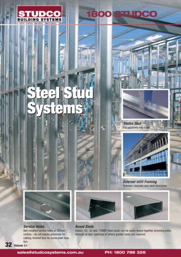
Table 1.3: Analysis results for 3:12 roof models3:12 Roof Slope: UnsheathedMember TypeTypical RafterJack Rafter (side)Jack Rafter (end)HipRidgeCeiling JoistMember #M42M106M114M230M232M15Axial Force at MaxMomentMax MomentMax Axial 0.459.1040.46-4.61-0.52-2.36-10.50-2.36-10.503:12 Roof Slope: SheathedMember TypeMember #Axial Force at MaxMomentMax MomentMax Axial Forcekip-incheskNmkipskNkipskNTypical RafterJack Rafter (side)Jack Rafter 4.681.205.36Ceiling JoistM15-4.61-0.52-2.76-12.28-2.76-12.28Table 1.4: Analysis results for 10:12 roof models10:12 Roof Slope: UnsheathedMember TypeTypical RafterJack Rafter (side)Jack Rafter (end)HipRidgeCeiling JoistMember #M113M121M136M35M89M15Axial Force at MaxMomentMax MomentMax Axial .882.229.88-4.61-0.52-0.84-3.75-0.84-3.7510:12 Roof Slope: SheathedMember TypeMember #Axial Force at MaxMomentMax MomentMax Axial Forcekip-incheskNmkipskNkipskNTypical RafterJack Rafter (side)Jack Rafter 281.25Ceiling JoistM15-4.61-0.52-0.85-3.79-0.85-3.7924
Table 1.5: Comparison of results between sheathed and unsheathed models3:12 Roof SlopeMember Type10:12 Roof Slope%%%%%%Reduction ReductionReduction ReductionReductionReduction(axial at(axial at(axial at(axial at(moment)(moment)moment)max)moment)max)Typical Rafter1.81%51.95%35.56%0.77%57.25%43.14%Jack Rafter (side)-0.17%24.33%-29.63%-1.41%78.75%70.83%Jack Rafter 86.76%97.45%87.75%87.39%Ceiling Joist0.00%-16.99%-16.99%0.00%-0.95%-0.95%Italics : Member sw itched from maximum compressive value to maximum tension value25
2.0 Hip Framing Analysis and Design2.1 GeneralHip members provide support for jack rafters and span from the building corners to theridge. They are orientated at 45-degrees to the building walls as shown in Figure 2.1. The hipmembers are assumed to be single span members with pinned ends. Based on the findingsdescribed in Section 1, the hip member for an unsupported hip roof framing system will haveconsiderable bending moment combined with a very significant axial compressive force.Additionally, the rafters that frame into the ridge member closest to the hip member to ridgeconnection also have a much higher axial load and bending moment than other rafters locatedfurther away from this point. The design of hip members and rafters for these high combined forcesmakes it uneconomical to construct these members out of cold-formed steel for unsupported hiproof framing systems. To essentially eliminate the axial force in the hip member and the excessiveaxial compressive force in the rafter, a column to support the upper end of the hip members wasintroduced at the point where the hip members and ridge meet. All rafters can then be treated as atypical rafter design as detailed in the Prescriptive Method (AISI 2002). The hip member isconsidered a simply supported, single span beam supported at the lower end by the building cornerand by the column at the upper end designed primarily for bending and deflection. Tables weredeveloped and are provided for hip members, supporting columns and connections.2.2 LoadsLoads used for the analysis and design of the hip framing are roof dead load (D), roof liveload (Lr), snow load (S) and wind load (W). ASCE7-05 (ASCE 2005) was used to determine theMWFRS wind load on the hip members, columns and their corresponding connections. LRFD loadcombinations were used from ASCE7-05 to identify the critical design moments for bending, axial26
loads and connections. The hip members were analyzed as simple span beams with a triangularload based on the tributary area. Figure 2.2 shows the tributary area for the hip members.2.2.1 Dead Load (D)The roof dead load of 7 psf used for design was taken from Table A1-1 of the PrescriptiveMethod (AISI 2002). The dead load was applied as previously described in Section 1.1.1 andshown in Figure 1.5.2.2.2 Roof Live Load (Lr)According to the Prescriptive Method, the minimum roof live load used for roof framing is 16psf. This load was applied on the horizontal projected area of the hip member.2.2.3 Roof Snow Load (S)Ground snow load was considered up to a maximum of 70 psf. The roof design snow loadwas determined by multiplying the ground snow load by 0.7 which is the current load determinationmethodology described in the Prescriptive Method. The calculated roof snow load was then appliedvertically on the horizontally projected area.2.2.4 Wind Load (W)For rafter design, component and cladding (C & C) wind loads are used in loadcombinations. The rafters receive wind loads from cladding which meets the definition of acomponent. Wind loads applied to the hip members and supporting columns were determinedbased on Main Wind Force-Resisting System (MWFRS) rather than C & C loads. Hip members areloaded primarily from the jack rafters with a minor portion coming directly from the cladding. Hipmembers also receive wind from more than surface which is another indication that the member is apart of the MWFRS. The assumption that MWFRS loads are to be used for hip member design isconsistent with the design of load bearing wall headers which resist both gravity loads and wind27
uplift loads from the rafters or trusses connected directly to them (ASCE 2004, ASCE 2005, AISI2003). The supporting columns also are designed using MWFRS wind loads because they receiveload from the hip members and not the cladding. The columns also receive load from threedifferent roof planes. Method 2 for MWFRS from ASCE7-05 for wind speeds from 85 mph to 150mph and exposures B and C was used to determine the wind pressures on the different planes of theroof. The wind load is applied perpendicular to the roof planes both for downward and upwardforces.For the development of the tables for member sizes and connections, simplifyingassumptions were made to reduce the number of different combinations of building configurationsthat would be needed for the determination of wind forces. For the maximum downward windpressures included with dead load and snow load, a 12:12 pitch roof was used. This produces themaximum downward force on the roof. For maximum uplift wind pressures a 24 ft. wide by 48 ft.long building with a 3:12 pitch was used. For both uplift and downward pressures a two-storybuilding was used with 10 ft. tall walls at each level.2.3 Load CombinationsThe following applicable LRFD load combinations from ASCE7-05 were considered for thedesign of the hip members, the supporting columns and all associated connections.1. 1.2D 1.6(Lr or S)2. 1.2D 1.6(Lr or S) 0.8W3. 1.2D 1.6W 0.5(Lr or S)4. 0.9D 1.6W(downward)(downward)(downward)(upward)Where:D Dead LoadLr Roof Live LoadS Roof Snow LoadW Wind Load28
2.4 Hip Member Analysis and DesignHip members are built-up sections consisting of a C-shape and a track section as previouslydescribed in Sec
1.1.2 Results of RISA-3D Analysis 10 1.2 Comparison of Unsheathed and Sheathed Roof Framing Systems 12 1.2.1 Analysis Summary and Comparison 12 1.3 Conclusions 12 . RISA-3D (RISA 2005) analysis and design software. Both sheathed and unsheathed models were built. All hip roof systems were analyzed assuming a 32 ft. x 60 ft. rectangular .