Transcription
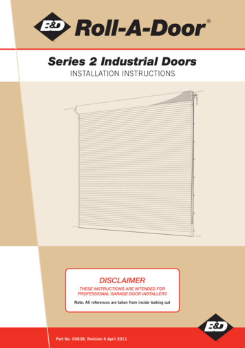
Roll-A-DoorSeries 2 Industrial DoorsINSTALLATION INSTRUCTIONSDISCLAIMERTHESE INSTRUCTIONS ARE INTENDED FORPROFESSIONAL GARAGE DOOR INSTALLERSNote: All references are taken from inside looking outPart No. 00838. Revision 6 April 2011
Roll-A-Door Series 2 Installation Instructions2CONTENTS1.0BEFORE YOU START31.1SAFETY CHECKLIST31.2PREPARATION31.3FASTENER RECOMMENDATIONS FOR FITTING GARAGE DOORS41.4REQUIREMENTS BEFORE INSTALLATION52.0INSTALLATION52.1FIXING REQUIREMENTS52.2BRACKET FIXING62.3POSITION DOOR ON BRACKETS62.4INSTALL GUIDES72.5SPRING TENSIONING BOTTOM RAIL STOPS82.6LOCKING83.0AFTER INSTALLATION CARERevision 6 April 201110
3 Roll-A-Door Series 2 Installation Instructions1.0 BEFORE YOU START1.1 SAFETY CHECKLISTThe following hazards and hazard controls have been identified for installers during the installation of this door.HazardControl Housekeeping - risk of slip trip or fallHousekeeping - risk of injury to other people or animals inthe installers work area Tidy up site prior to start work as a minimum area should beat least the area of the installation back into the garage and2 metres in frontIf the Site housekeeping is deemed to be unsafe do notinstall the doorKeep all people well clear of installers work area withappropriate signage and discussion with ownerManual handling when moving the door from the Trailer orUte to the installation area - risk of musculoskeletal injuryManual handling when installing Doors & Openersparticularly above head height - risk of musculoskeletalinjury or twistingManual handling when installing tracks and torsion bars risk of musculoskeletal injuryManual Handling when installing the door opener - risk ofmusculoskeletal injury or twisting Correct lifting technique for Roller DoorUse of 2 person liftsUse of mechanical aids such as lifting stands,forklift, cranesAvoid twisting (Practice correct lifting techniques)Correct use of ladders while installing tracksUse of correct technique of knotted rope installation aids Working at heights and working with ladders, scissor lifts,scaffold - risk of fall from height Ladder checkLadder placementDo not work off the top rung Sharp edges on Door, tracks or related jewellery - risk oflaceration Wear appropriate PPE (Dyneema cut off Gloves)Follow instruction explicitly particularly for the installationof some parts of the doors as the unrolled cut out edgespresents a very sharp edge Pinch points - risk of cut, puncture or crush injury Wear appropriate PPE and keep hands well clear of pinchpointsEnsure hands well clear of the panels Use of hand tools - risk of eye injury, laceration cut stab orpuncture injuries (Tools checklist)Use of Electric/ Battery or pneumatic tools - noise hazardUse of cutting tools creating sparks - risk of fire Tension spring - risk of release of stored energy (variousdoor parts, tools, jewellery striking installer on the head orbody) Position the door on the brackets, there is a risk of the doorfalling from the brackets striking a person Wear appropriate PPE and utilise operators manualUse appropriate noise/hearing protection in the form of earplugs or ear muffsEnsure appropriate fire protection available andhousekeeping to ensure that flammable liquids or materialsare removed from the area of workEnsure door is correctly securedEnsure that pipe wrench is fitted correctly to the axle and ifit is gripped onto the axle do not underestimate the tensionin the spring when undoing the clampsEnsure the correct length pipe wrench is utilisedEnsure correct bolts are tightened or loosened to ensurethere is no release or controlled release of energy from thespring through the pipe wrenchKeep hands clear of the pipe wrench at all timesKeep head clear of the pipe wrench at all timesEnsure the door is immediately fastened to the bracket withthe “U” BoltEnsure no-one ever walks under a door sitting on a bracket1.2 PREPARATIONDO NOT CUT THE PACKAGING THAT HOLDS THE DOOR IN A ROLLAt a later stage during the installation you will be told just when to cut the packaging.Remove brackets, guides and bag of small parts from each end of the door roll.Because B&D Roll-A-Doors overlap the opening on each side, the door and opening widths should bemeasured to determine the amount of door overlap to enable correct positioning of the brackets.Revision 6 April 2011
4 Roll-A-Door Series 2 Installation Instructions1.3 FASTENER RECOMMENDATIONSFOR FITTING GARAGE DOORSMATERIALFASTENER C Sleeve Anchors (Dyna Bolts)12mmX55mmHRD-VGK or HGK-VGS (Hex Head) Frame Anchors10mmX60mm5/16”X1½”Macplugs (wall plugs) to suit aboveNew Hollow BrickLENGTH OF FASTENER(See Note)5/16”Coach Bolts (Hex Lag Screw)- combined with wall plugsNew Solid BrickDIAMETEROR TYPECoach Bolts (Hex Lag Screw)- combined with wall plugs3/8”X2”5/16”X50mm3/8”X60mmHLC Sleeve Anchors (Dyna Bolts)12mmX55mmAerated Concretee.g. (HEBEL)Fischer Nylon Twist Lock Anchor TypeGB 1414mmX85mm5/16”X1”Steel Framinge.g. BHP Framing(with rear access)Hex Head Bolt Zinc Plated,Hexagon Nuts Zinc Plated,Washers Zinc 4-10X50mmNew Solid ConcreteHeavy Gauge SteelLight Steel Framinge.g. BHP HouseFraming(no rear access)Macplugs (wall plugs) to suit aboveHex Head TekHeavy Duty Kap ToggleHex Head TekCoach Bolts (Hex Lag Screw)New TimberHex Head TekIMPORTANT NOTES:1. For installation to materials not covered in the above chart, the installer should seek expert advice from a qualified builder.2. Minimum length of fastener does not exclude use of longer lengths. Decision must be made by fitter to ensure adequate strength.3. Recommendations for old materials or materials not in good condition are not included. If in doubt about the strength of the material seek specialistadvice.4. Fasteners for sectional door spring brackets and top track brackets in masonry should be at least 5/16” x 2.5” long or metric equivalent.5. HEBEL Fischer type fastener should be installed 150mm from edge of blocks. Minimum overlap of door should be approximately 115mm (S1),110mm (S3) and 90mm (Panelift). Add 50mm more if mounted on panels instead of blocks.IMPORTANT INFORMATION ON FASTENERSCoach bolts/screws supplied with this product are suitable for fastening to timber jambs.Correct and safe fastening to other materials may require different fasteners.The installer must select and use fasteners appropriate to the material into which they are being fixed.Revision 6 April 2011
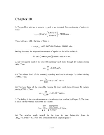
5 Roll-A-Door Series 2 Installation Instructions1.4 REQUIREMENTS BEFORE INSTALLATIONB&D Roll-A-Doors are normally installed to operate behind theopening, overlapping as described in the dimension sketch,opposite. Openings should therefore have sufficient return onboth sides to accommodate the support brackets and doorguides, with necessary working clearances.A1DCurtainPLANBThe door is supported on brackets above the opening at each endand requires headroom for the door to roll up in (see DimensionPanel). Consequently, piers or door posts must continue up pastthe top of the opening to provide fixing for the support brackets.A1A2CHAIN WHEELDOORSIt is preferable that lintels (or ‘heads’) be built flush with, orslightly forward, to the back of the door posts if possible. Thisavoids an excessive gap between the door and the lintel, whileallowing sufficient working clearance to prevent the door rubbingagainst the back of the lintel.DOOR SIZE – Width: The door curtain should be 100mm (seeDimension Panel) wider than the opening. However, a wider thannormal door can be fitted by allowing the door to overlap furtheron each side, providing the additional sideroom is available.A2BChain wheel pulleyNORMAL HEADROOMRESTRICTED HEADROOMFFC1LintelC2LintelE2E1END VIEWHeight: A door can not be installed higher than its maximum size;however, it can be installed in a lower position (providing the doorguides are cut to suit – as shown later).END VIEWCeiling LineCIf the opening is too high, the door should be installed at themaximum door height position and the opening reduced ortreated as shown in Step 2.2 under the heading “Bracket Fixing”.Lintel LineguidesWARNING! No guarantee will be given or responsibility acceptedby the manufacturers if the door is not installed as instructed. Forsatisfactory door operation please follow the instructions carefully.NOTE: If the chain mechanism is fitted to the R/h side A1&A2detail is reversed and 40mm must be added to the A1measurement.ELEVATIONDaylight openingNOTE: Hand operated doors up to 2400mm high, the bottom railwill hang 65mm below lintel. For doors over 2400mm high bottomrail will be level with lintel.DIMENSION PANELHEIGHTUp to 2400Up to IDTHUp to 5500Over 5500Up to 5500Up to 5500Over 5500Up to 5100Up to and OperatedHand OperatedDirect DrivePlanetary GearingPlanetary GearingPlanetary GearingPlanetary Gearing*C2, E2, G Dimensions are for Restricted Headroom Installations Only, (G Height of guide top above bracket arm see Step 4).Dimensions are recommended and suit Normal Headroom Installations, top of guide will be level with top of bracket arm (i.e. G).All measurements are in millimeters and are minimum unless otherwise shown.NOTE: It is not recommended that doors fitted in restricted headroom be fitted with openers.2.0 INSTALLATION2.1 FIXING REQUIREMENTSFor attachments to good timber work, coach screws are the standard fixings supplied with B&D Roll-A-Doors. When installing ontomasonry special fixings will be required. PLEASE REFER TO THE SEPARATE B&D FASTENER RECOMMENDATION GUIDE OR SEEKFURTHER ASSISTANCE.It is the installers’ responsibility to ensure that the fixing method is sound.When deciding the fixing method, dynamic loads on door brackets as well as the door weight must be considered.Revision 6 April 2011
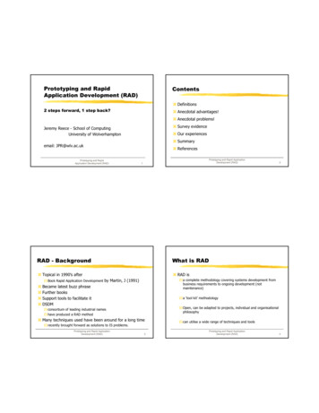
6 Roll-A-Door Series 2 Installation InstructionsALTERNATE METHODS OF ATTACHING BRACKETS AND GUIDESRightHandBracketFor Guides:Use the 40mm x 8mm (1V x 5/16”)coach screws supplied, with a goodquality plastic masonry plug or suitablemasonry anchors.NOTE TO BUILDERS:Masonry blockwork should be properlyfilled and reinforced if brackets are tobe mounted directly to blockwork withmasonry anchors. Where the blockworkis not solidly filled but structurally sound,long bolts should be passed through theblockwork using suitable steel platesunder bolt heads.Special consideration should be givento brick type and construction of wall,to ensure satisfactory fixing e.g. weldingdetail if fixed to steel.STEELCONSTRUCTIONBRICKCONSTRUCTIONFor Brackets:Use six 10mm (3/8”) bolt size masonryanchors; (dynabolts or similar).MasonryAnchors(minimumbolt size10mm 3/8”)WeldBolt Guidesto steelworkLeft HandBracketMASONRY BLOCKCONSTRUCTIONSECURE GUIDELong BoltsCoachScrewsintomasonryplugsSteel PlateRight HandBracket2.2 BRACKET FIXINGCheck the opening dimensions to ensure you have the correctdoor size. Check floor and lintel levels and work from the lowestside or from the side with the least headroom. Mark out firstbracket after checking dimension panel for height of bracketsabove lintel, E1 for normal headroom installation and E2 ifheadroom is restricted. (If insufficient headroom, measure downfrom ceiling or obstruction using dimension C1 or C2 and mark anew line and treat as the lintel). Mark out one bracket, drill andfix after allowing sufficient side clearance for door curtain Usinga water level or a straight edge and spirit level, transfer positionof top of first bracket arm to opposite side of opening, thenmark, drill and fix second bracket. (NOTE: the brackets mustbe perfectly level for correct door operation). Also ensure thatthe brackets are secure and the correct fixings have been used.REFER TO THE SEPARATE B&D FASTENER RECOMMENDATIONPAGE.Ceiling line or lowest obstructionTop of Bracket Arm LineFC1 C2E1 E2Lintel LineAllow for width ofdoor curtain plusDimension ‘B’ clearanceNOTE:1. Where possible, and for best performance, doors should be installed in the normal headroom position. The restricted headroominstallation should only be used where headroom is restricted and is not recommended for electrically driven doors.2. The bottom rail of doors below 2400mm high will hang below lintel and reduce walk in height by 65mm. For doors above 2400mmhigh, the bottom rail will be flush with the lintel.3. Where insufficient headroom exists and brackets are placed above a marked lintel line it may be necessary to fit a false head orlintel to improve appearance of the installation and to improve cover.2.3 POSITION DOOR ON BRACKETSWith the door the correct way round (the curtainrolls down the rear of the opening) carefully lift dooronto the brackets using block and tackles attachedto the door axles, or other suitable lifting equipment– avoid curtain damage.A.Position Bottom Rail here“U” bolt Axle ClampFor Doors up to 3000mm High withSingle Saddle and “U” Bolt FixingSaddleRevision 6 April 2011
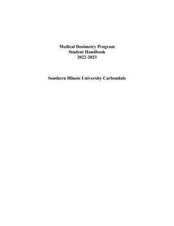
7 Roll-A-Door Series 2 Installation InstructionsFor doors up to 3000mm high, rest axle on cast iron saddle.Rest axle on cast iron saddle. Immediately loosely secure with“U” bolts, nuts and washers, through slots in bracket arm. Thiseliminates the door falling from the brackets (See sketch).Position Bottom Rail hereKeeper PlateB.For doors over 3000mm high, rest axle between two cast ironsaddles. Immediately loosely secure with “U” bolts, nuts andwashers, through slots in bracket arm. This eliminates the doorfalling from the brackets (See sketch). (See sketch below) Ifchain gear is fitted, ensure that the chain is placed around thechain wheel and hangs down freely.C.25mm x 5mm Plate10mm BoltsAxleCast Iron SaddlesBracket ArmDouble SaddleFor Doors up to 3000mm High with DoubleSaddles through Bolts and Keeper PlatesWashers25mm x 5mm PlateBefore tightening “U” bolts or saddle bolts, position the door1. So that it overlaps the opening evenly both sides.2. So that the axle is positioned on the bracket arm slots as far forward as possible, while still allowing the bottom rail to pass the lintelwhen the door roll is rotated. (See sketch B)3. Rotate both the door and the axle so that the bottom rail is level with the bracket arm. (See sketch B) Now tighten the “U” bolts orsaddle bolts very tightly, using washers under nuts, to a torque of 40 newton metres or 30 ft.lb.WARNING: Axle must be securely clamped otherwise door will lose spring tension.2.4 INSTALL GUIDESGuides must be the correct length. The guide top is to be level with the top of bracket arm for preferred “normal headroom” fixing orabove the bracket arm by dimension G for “restricted headroom” fixing. If guides need to be shortened cut from bottom of guide.GBracket ArmCushion Head StopGUIDE LENGTH – PREFERRED HEADROOMTop of guides should be level with top of bracket arm for all door heights.This is the recommended position for electrically driven doors.GUIDE LENGTH – RESTRICTED HEADROOMDOOR HEIGHTDIMENSION GUp to 4200mmMax 65mm4200mm to 5100mmMax 45mmGuide LugChain WheelPosition guides true and plumb at each side of the opening. Allowing 3-4mm of workingclearance between the door and the inside of each guide, mark, drill and fix both guides.Use the 10mm (5/16”) coach screws and washers supplied (with suitable plastic plugs formasonry application or other fixings to ensure satisfactory attachment. (Note: Welding ofguides to steelwork is usually not recommended).SpiritLevelChain ClipCORRECT BENDING OF S2 GUIDE LEAD-IN15mm (NOM.)45 CREATING PROPER GUIDE LEAD-INThe shape of lead-in is critical for successful door operation and trouble free performance.m5mGuide Lead-InFormTop Door StopThe shape of lead-in needs to be formed by the installer and normally should be as shown on left.Correct bending method:1. With multigrips, bend top 5mm of lead-in approximately 45 to prevent Nylofelt catching onlead-in.2. Bend lead-in from door stop to top of lead-in (along press cut), to finish 15mm from its originalposition.3. Ensure the brackets are installed properly by checking curtain operation over the lead-in.NOTE: Installer may require to increase the 15mm dimension for larger door heights to ensure thesmooth operation of the door.Revision 6 April 2011
8 Roll-A-Door Series 2 Installation Instructions2.5 SPRING TENSIONING BOTTOM RAIL STOPSCheck top of guide lead in to ensure that the door does not make contact when rotated. Damage to Nylofelt could result. The curtainmust feed in smoothly without bumping – adjust lead in as required.Apply, tension to the springs by rotating door approximately two (2) complete turns in a forward direction (see arrow on sketch A)after ensuring axle is securely clamped. The amount of tension required for satisfactory operation may vary with individual doors,depending on size. Final adjustment should be made later.A.ROTWARNINGOnce the packaging containing the door roll is cut, the door will havea strong tendency to rise and revolve. If uncontrolled, the rapidlyunrolling door could cause damage or injury. Therefore, it must besecurely held until bottom rail stops are fitted. Chain wheel doors canbe held in position by locking the chain in the chain clip attached tothe left hand guide.E TO APPLAT SIO YTEN NHold door firmly and cut the packaging. Feed door down into guidesbelow head stop.Fit bottom rail stops using self locking nuts provided. Allow door torise and to rest against head stops. (See sketch B.)FINAL ADJUSTMENTOperate door up and down a number of times to check operation.If operation is uneven or not smooth, rectify as below: –Self lockingNutsB.Faults1. Door hard to operate in one direction.2. Door hard to operate in both directions.3. Door is stiff to work and rattles over lead in on top of guides.4. Door is scraping in the guides.WARNINGDo not grease the guides. Grease will damage the Nylofelt running strips and make doors heavier to operate.Remedies1. Adjust spring tension.2. Check guide clearances (see that door is not jamming). Also check that the inside surfaces of the guidesare clean and free of any oil film. Use a spirit cleaner if necessary. Polishing the inside surfaces of theguides improves operation.3. i) Check that guides are not too long. Move the door closer to the lintel.ii) With the door up and chain secured, loosen one “U” bolt/saddle bolt and push that side of the doortowards opening as far as possible without scraping lintel. Tighten the “U” bolt and repeat operationwith the other side, ensuring that the axle is still parallel with opening.iii) Pack out top lug of guide.4. Check that the guides are plumb, the clearances are correct and the door is correctly centred with theopening. Also check that the brackets are level.2.6 LOCKINGINTERNAL WAIST HIGH SLIDE BOLT(Left hand side shown – viewed from inside.)With door fully closedcheck that bolt slidesthrough guide. Adjusthole if necessary.Revision 6 April 2011
9 Roll-A-Door Series 2 Installation InstructionsMETHOD OF FITTING OPTIONALPADBOLT TYPE LOCKINGSELF ADHESIVE LOCK BAR RETAINERSPosition as indicated and clean the surface before proceeding.Wave WasherFlat Washer1. Peel back and stick in position.2. For additional strength drill 2 x 1/8 holes from inside usingretainer as a template.3. Fit 2 x 1/8 pop rivets to each retainer from the face of the door.Outside Locking BarADJUSTING SPRING TENSION IF NECESSARYBottom RailInside Locking BarLOCKING BAR ASSEMBLYHead StopIMPORTANT– See NoteIMPORTANTHead-stop must besecured to slide bolt asshown in drawing beforedoor is operated. Failureto do so will result inunrolling of door causingdamage.CENTRE LIFT LOCKa. Undo screws to separate lock from faceplate.b. Fit faceplate to outside of door. Fit hooks onto curtain edge,then slide faceplate as far to the right as possible. Useadhesive tape to hold in position.c. Attach the lock body to the faceplate from the inside, using themounting screws and washers. Do not over-tighten the screws.d. With the door in the closed position make the lock holeposition in the side guides.e. Drill and file out a rectangular slot on longer than 25mm andno wider than 10mm. Ensure top of the slot remains in linewith top of locking bar.f. Slide bars through guide slot, then back, onto lock arms.Screw on securely using 4mm x 6mm screws supplied.g. Fitting the lock hole cover requires the surface to be cleanand dry. Peel the lining from the lock hole cover and positionover the hole taking care that the movement of the lock bar isnot impaired.Hand Operated and Direct Drive Doors OnlyWith door in open position (rolled up), tie two ropes right arounddoor approximately 12” from each end. With a person at eachend secure a firm hold on axle with stilson or pipe wrench andloosen axle clamp with socket spanner. Axle can then be rotatedin required direction (see diagram below) until approximatetension is gained. It is recommended that alteration to springadjustment be only by small degrees till the best position Isfound. Axle clamps must then be re-tightened to a tension of 40Newton metres or 30 ft.lbs. Before releasing hold on pipe wrench(stilson). Repeat process if spring still requires further tension.Pipe wrench atleast 450mm(18”) longHold axle beforeloosening“U” boltTo loosenspring tensionPULLTo tightenspring tension“U” boltsto be loosenedat both endsWARNING: Hold Axle before loosening “U” bolts.IMPORTANT: Do not attempt to loosen “U” bolts before securingfirm hold on Axle with Pipe Wrench (stillsons). Do not use filtersor similar brittle steel tools such as Tommy Bars.Doors with Planetary Geared Chain Wheel OnlyIf the door tension needs adjusting and the door is fitted withPlanetary Gearing then follow the steps below:1. Ensure that the door is in the OPEN position2. Secure a rope around the centre of the door roll and use vicegrips to clamp the guides just under the bottom rail of thedoor to prevent the door from closing suddenly during the retensioning process.LockBarCover3. Secure both chains in the chain clip.This end firstDouble SidedAdhesive TapeAttach selfadhesive lockbar retainers4. Carefully loosen the axle clampsHOOKS(a) Faceplate(e) Lock ArmCut(c) Locking BarLockBarCoverRevision 6 April 2011(b) LockBody(d) Cutouts5. Adjusting Tensiona. To increase spring tension, carefully pull down on the rearchain, Lock the chain in the chain clip.b. To reduce spring tension, hold the rear chain firmly,carefully release chain from the chain clips and allow therear chain to move upwards, take care that the full tensionis not removed from the springs. Lock the chain in thechain clip.NOTE: As a safety precaution to protect both the door and theinstaller, lock a section of the chain in the chain clip so that thechain is restricted to short movements.6. When the tension is correct, secure the chain in the chain clipand re-tighten the axle clamps to the correct tension.7. The correct adjustment will only be found by trial and error,adjustments should be restricted to approximately onerevolution of the chain wheel.
10 Roll-A-Door Series 2 Installation Instructions3.0 AFTER INSTALLATION CAREREGULAR MAINTENANCE REQUIREDGENERAL CARE OF YOURSERIES 2 INDUSTRIAL DOORCLEANINGCOLORBOND & COLOURED STEEL FINISH Your B&DSeries 2 Industrial Door has been pre-painted with a siliconemodified polyester formulation, which is one of the best paintfilms commercially available today. However, all exposedsurfaces require some attention to guard against the prematureonset of corrosion and any other harmful atmospheric effects.In our atmosphere there are harmful deposits that gather onthe door surface and if not removed regularly, will seriouslyaffect the appearance and life of the door.B&D recommends that you check the operation of your Series2 Industrial Door at least every six months (more regularly inextreme environments or frequent use). The effort required tomanually open and to manually close the door should be aboutthe same (if door has an automatic opener, put into manualmode before testing door).NOTE: do not grease or oil the guides on doors fitted withNylofelt.If the door is difficult to operate in either direction (up or down)then check that the inside surfaces of the guides are clean andfree of obstructions.Washing of the door with clean water and a cloth every 14 daysis recommended – particular care should be taken to cleanareas of the door not normally washed by rain.If the door is still difficult to operate, then your door will needa service to adjust the spring tension and possibly otheroperational parts of the door.LOCKThis service should only be carried out by an experienced doortechnician, using the correct tools.Your lock does not require special maintenance, however, if thekeyway becomes stiff, the application of powdered graphite isrecommended – do not grease or oil the lock.WARNING! Do not disassemble the lock mechanism and donot allow paint to enter the lock keyway.If you have an automatic opener fitted to your door, it isparticularly important that you ensure the optimum operation ofthe door, otherwise you may reduce the effective life of the opener.To keep your door running well, it is recommended that yourdoor be serviced, by an experienced door technician, every 12months (more regularly in extreme environments or frequentuse), or earlier if required.SPRING TENSIONIt is natural for springs to lose tension over time. When springtension is adjusted or when your door is first installed it is usualto apply a little more tension than is required for balancedoperation, to allow for the normal “settling in” of the springs.WARRANTYThe B&D Series 2 Industrial Door in residential use is coveredby a 12 month warranty for complete door and parts, surface(excludes salt corrosion).Warranty conditional on proper care as recommended above.Full details of the warranty are available from www.bnd.com.auB&D Doors Office Locations:New South Wales:34 Marigold St, Revesby 2212.Phone: (02) 9722 5555South Australia:23 Frederick Rd, Royal Park 5014.Phone: (08) 8440 4747Queensland:17 Oasis Court, Clontarf 4019.Phone: (07) 3883 0200Western Australia:96 Mulgul Rd, Malaga 6090.Phone: (08) 9247 8777Newcastle:Unit 1/108 Mitchell Rd, Cardiff NSW 2285.Phone: (02) 4956 8533International/Export:34 Marigold St, Revesby 2212.Phone: 61 (0)2 9722 5555Victoria:147-153 Canterbury Rd, Kilsyth 3137.Phone: (03) 9237 7766YOUR REPRESENTATIVE ISPrefixed trademarks are the property of B&D Australia Pty LtdB&D Doors & Openers is a division of B&D Australia Pty Ltd, an Alesco companyABN 25 010 473 971Copyright 2011 B&D Australia Pty Ltd.Website: www.bnd.com.au
e.g. (HEBEL) Fischer Nylon Twist Lock Anchor Type GB 14 14mm X 85mm Steel Framing e.g. BHP Framing (with rear access) Hex Head Bolt Zinc Plated, Hexagon Nuts Zinc Plated, Washers Zinc Plated 5/16" X 1" 3/8" X 1" 10mm X 25mm 12mm X 25mm Heavy Gauge Steel Hex Head Tek 14-20 X 22mm Light Steel Framing e.g. BHP House Framing (no rear access)